How to Make [Almost] Anything | Life + Times Of v.2019
Maharshi Bhattacharya | Masters in Design Studies
Harvard University | Graduate School of Design
Maharshi Bhattacharya | Masters in Design Studies
Harvard University | Graduate School of Design

In the 5th week we had to redesign + redraw
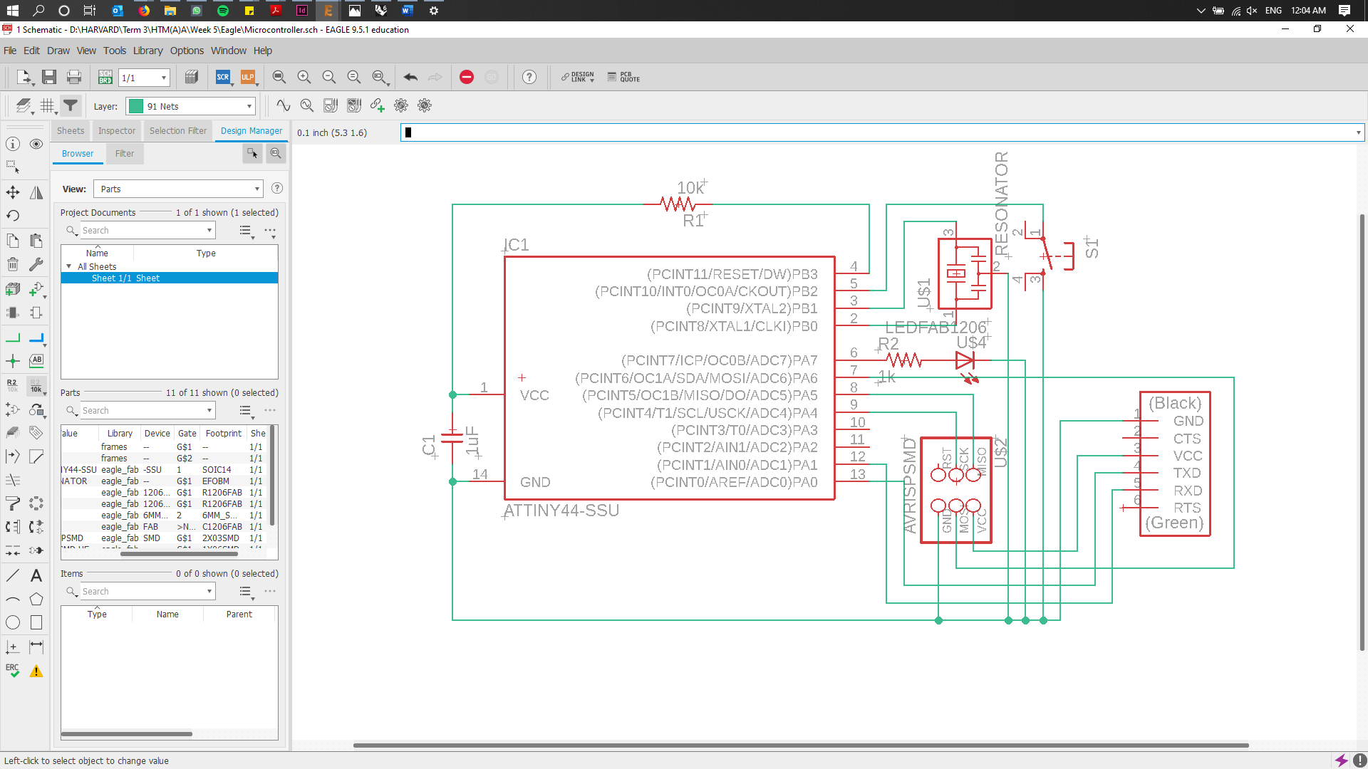
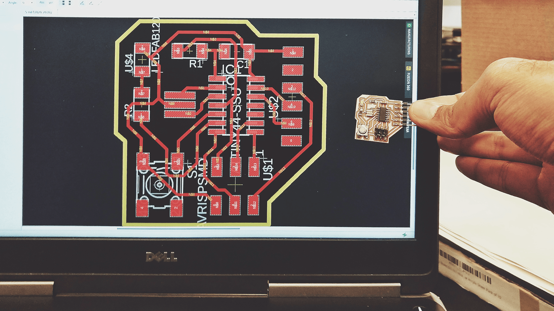
Using Autodesk Eagle, I had to draw the Circuit Schematic. This turned out to be an exercise in understanding what components will be part of the board and what components are connected where. This exercise also helped me practice my Eagle skills.
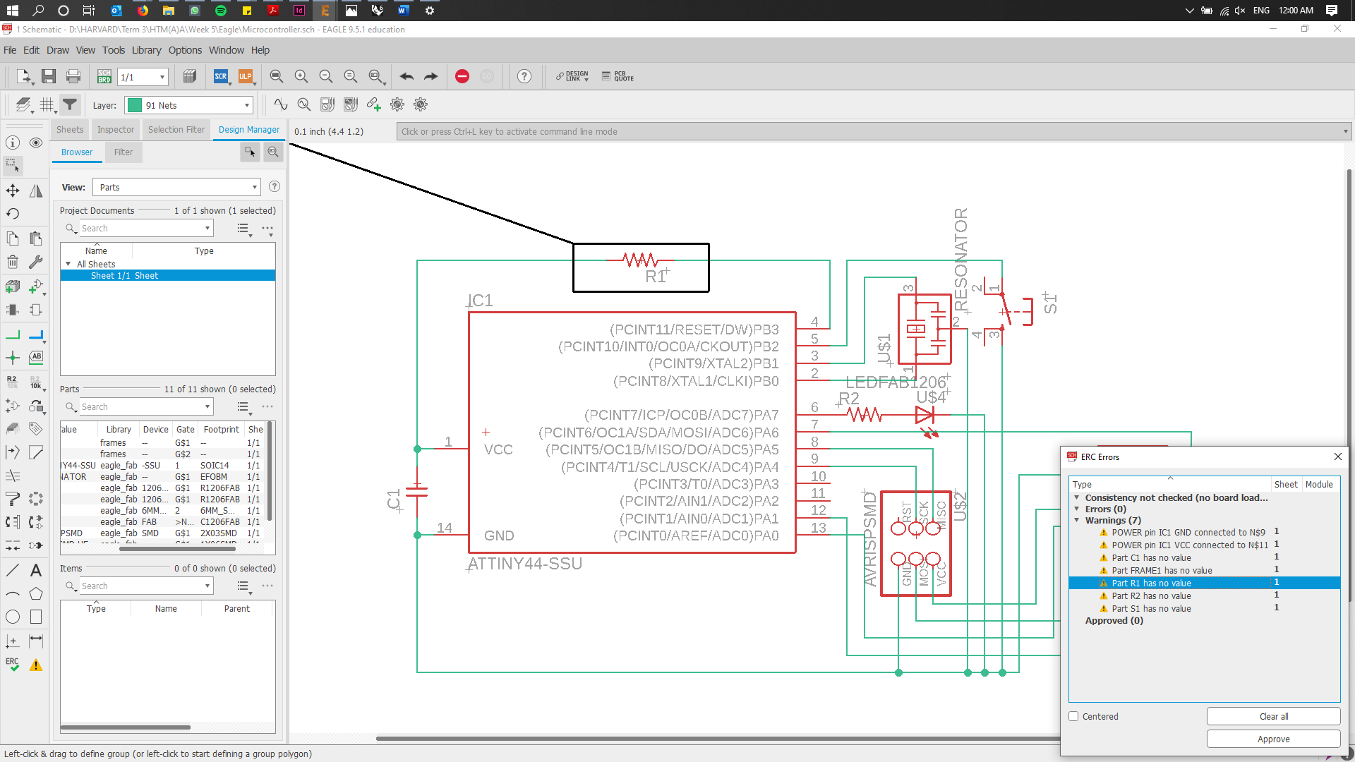
Errors!! Although errors showed up, Rob helped with them and eventually the sketch was all good. Steep learning curve!
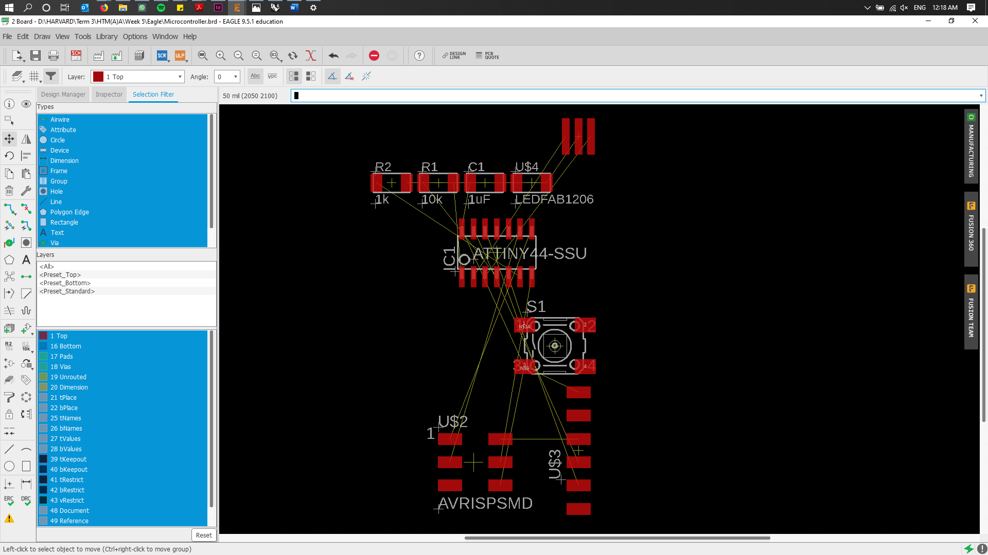
Exported the Schematic to the Board Space to redesign + redraw for milling.
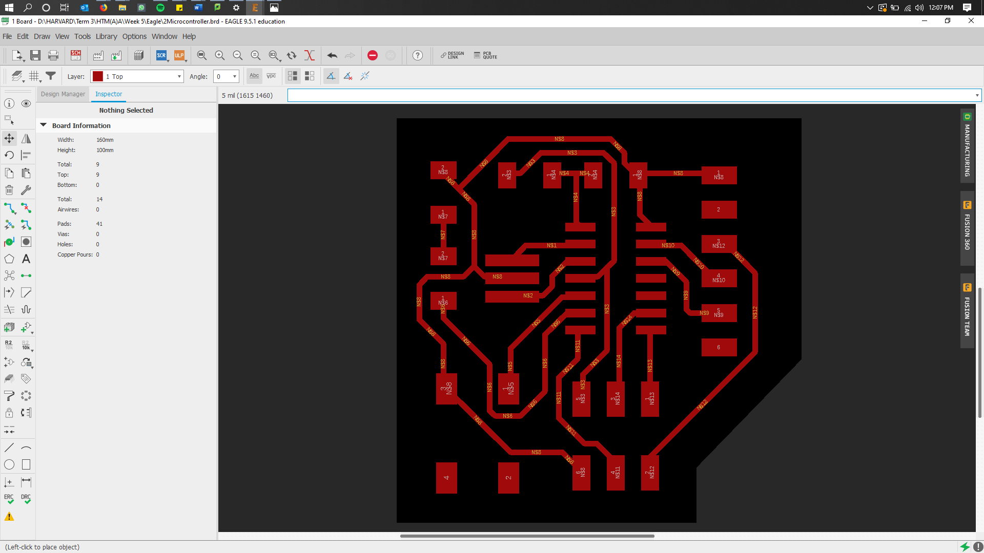
At first, moving and rotating components to find the best arrangement, with the intention of avoiding any "via-holes", proved quite tedious and time consuming. However, in this process I learnt two things: design rules for the milling route and Autorouting. Once I adjusted the design rules (route width and spacing: 15mil), I alternated between running the Autoroute operation and tweaking the routes to get the best-fit result. I would edit each result to remove vias and optimize space usage and ran the Autoroute again, till I got a result that I liked. In the video here the red lines are regular route lines and the blue lines are vias."
Right before the Board is exported into a monochome png file. The red lines/marks denote the milling toolpath.
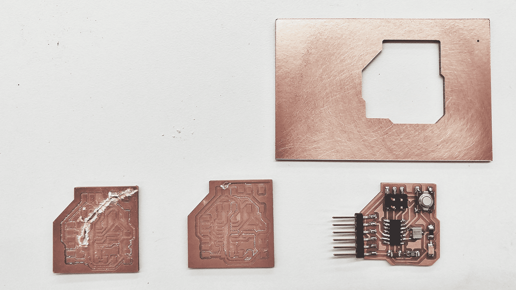
The Golden Line denotes the route along which the board is cut from the parent board. However, because of the thickness of the outer cutline, the milling mod created 2 toolpaths for that one cutline. This caused the inset part to detach from the parent board, after one toolpath was run and before the cutting was accomplished, damaging the board as a result.
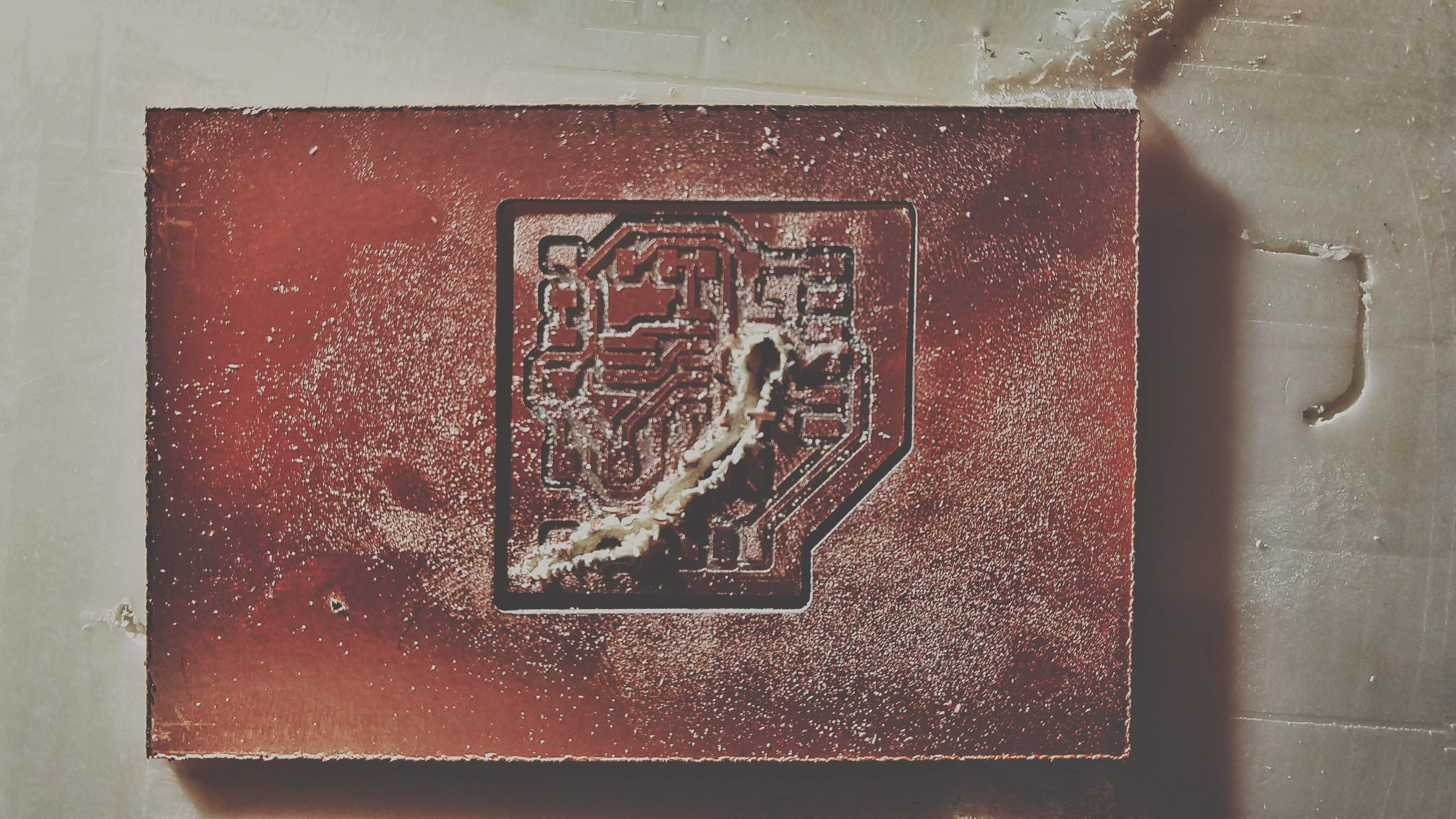
Mistake with cutline tootpath that eventually damaged the board, due to untimely detachment from parent board.
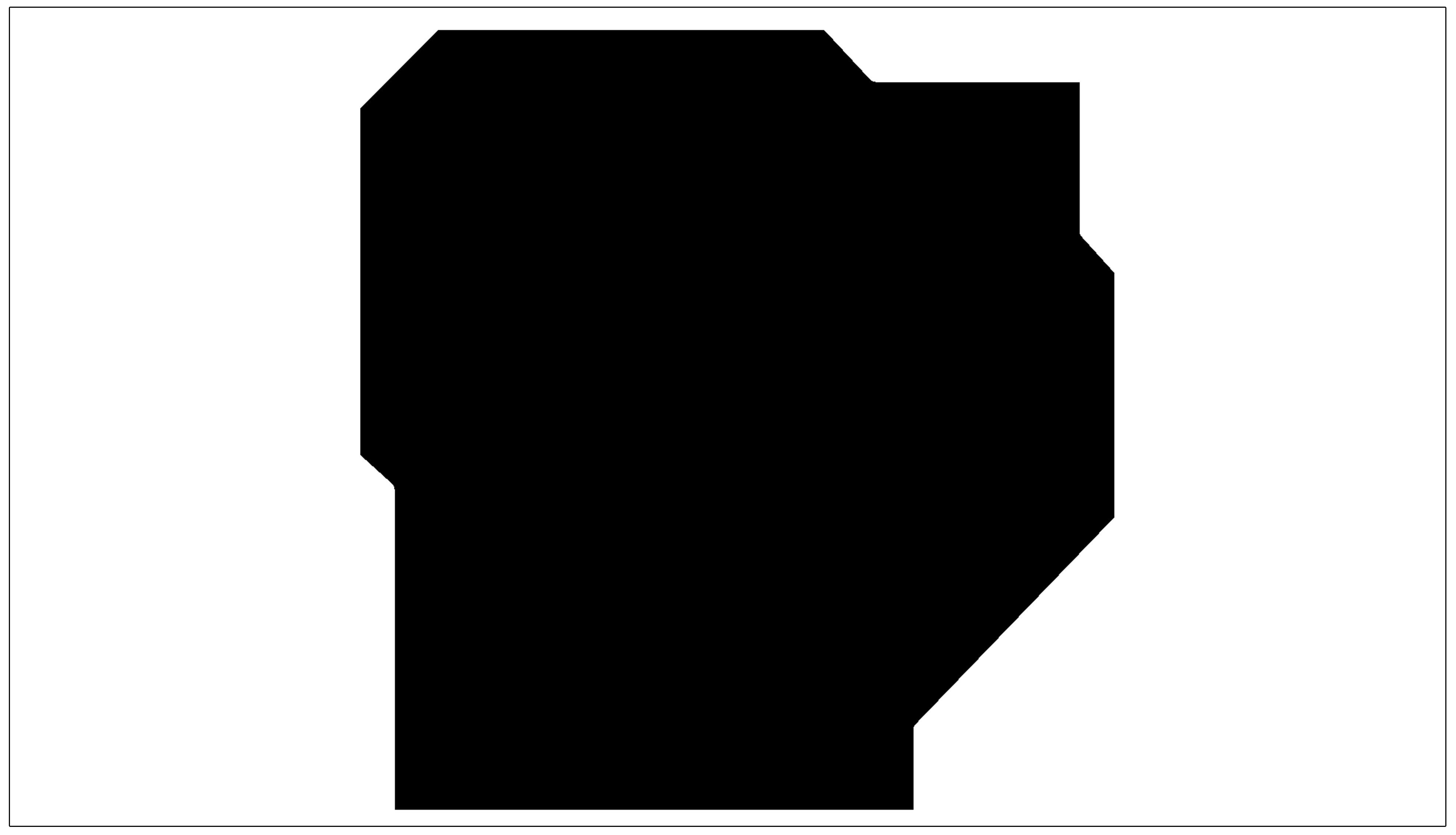
In order to prevent what happened with the last board, instead of having a thick line as the cutline I used the entire region (white part). This made the mod create just one toolpath for cutting the board out of the parent board.
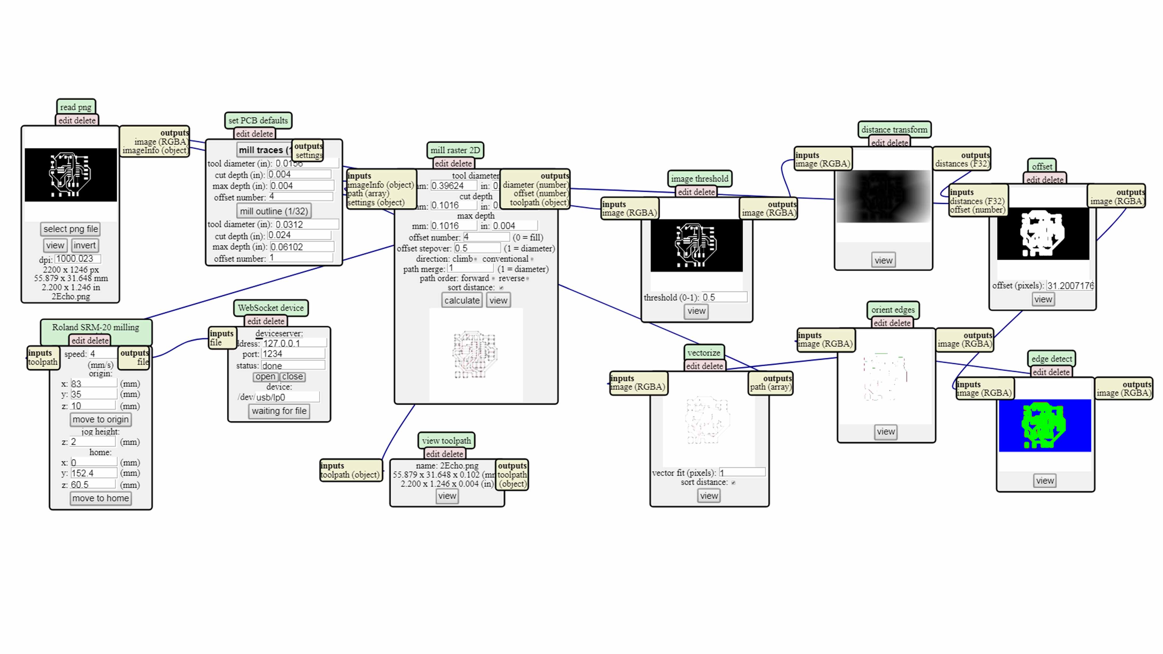
The mod used for milling.
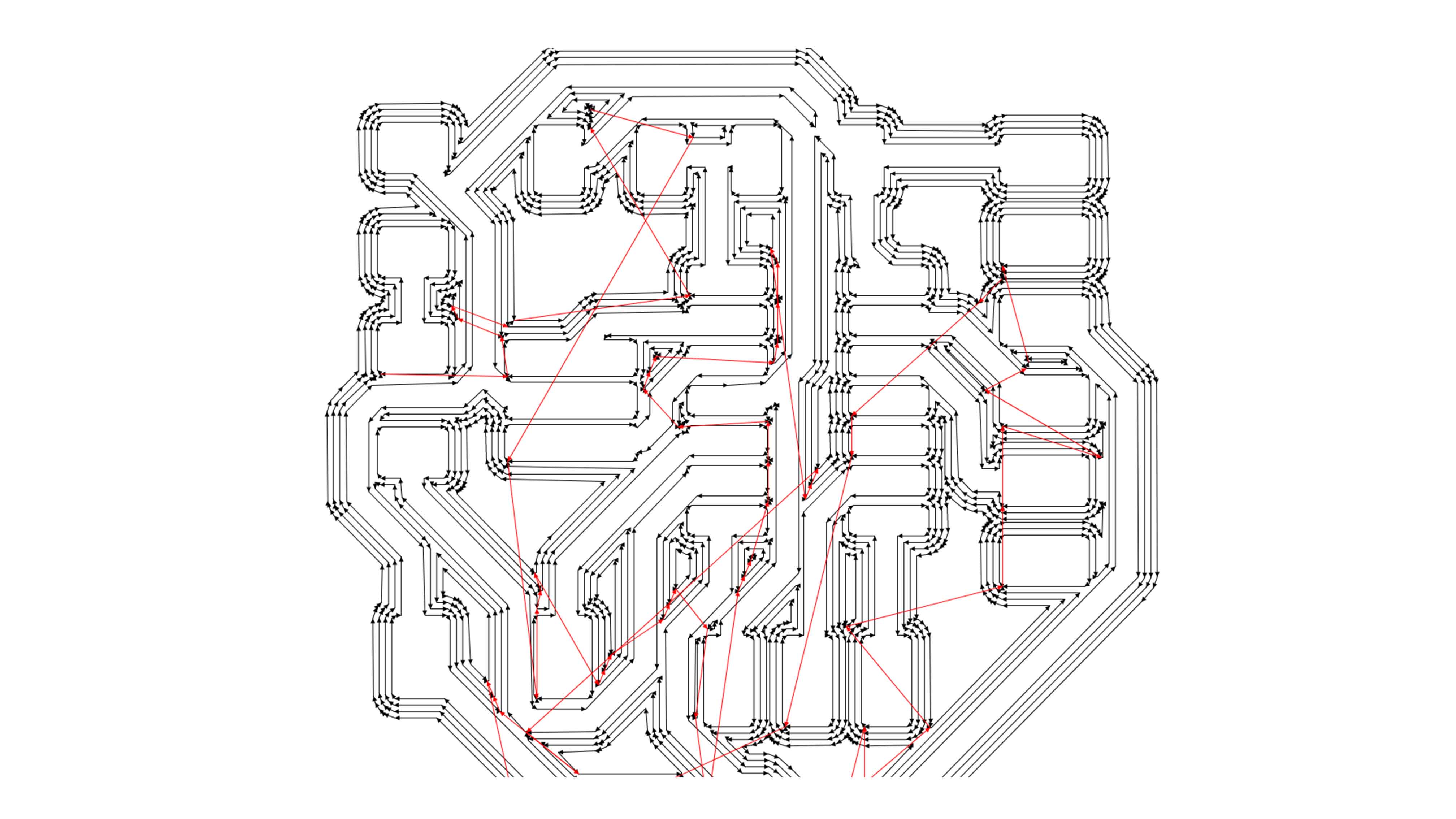
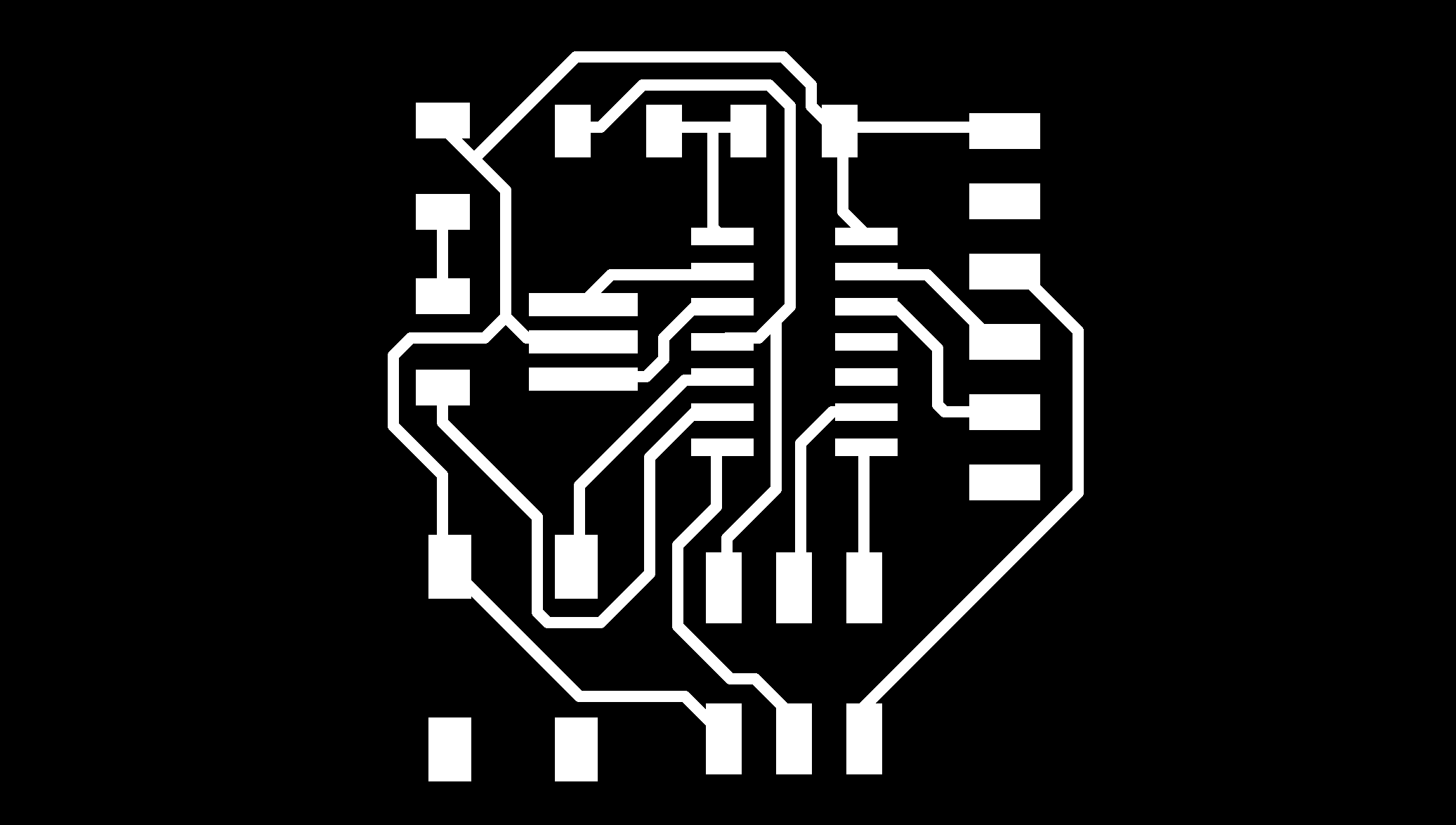
The toolpath generated by the mod.
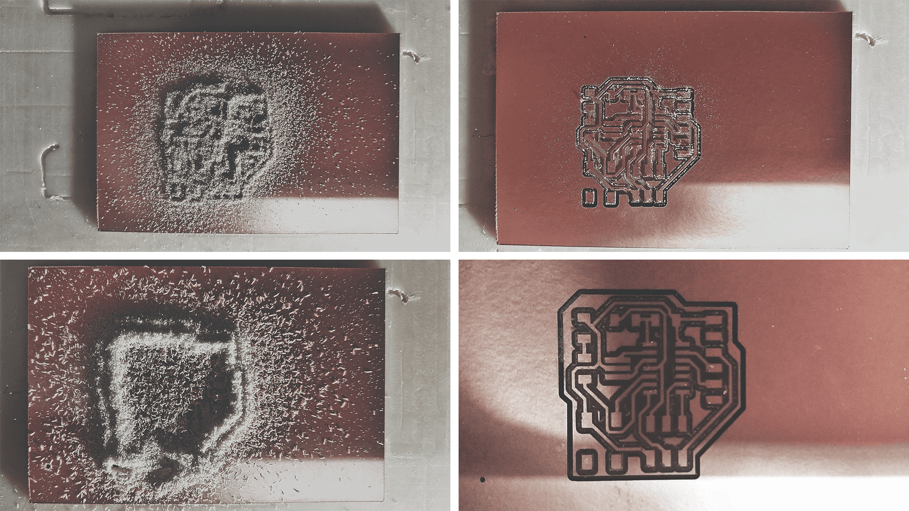
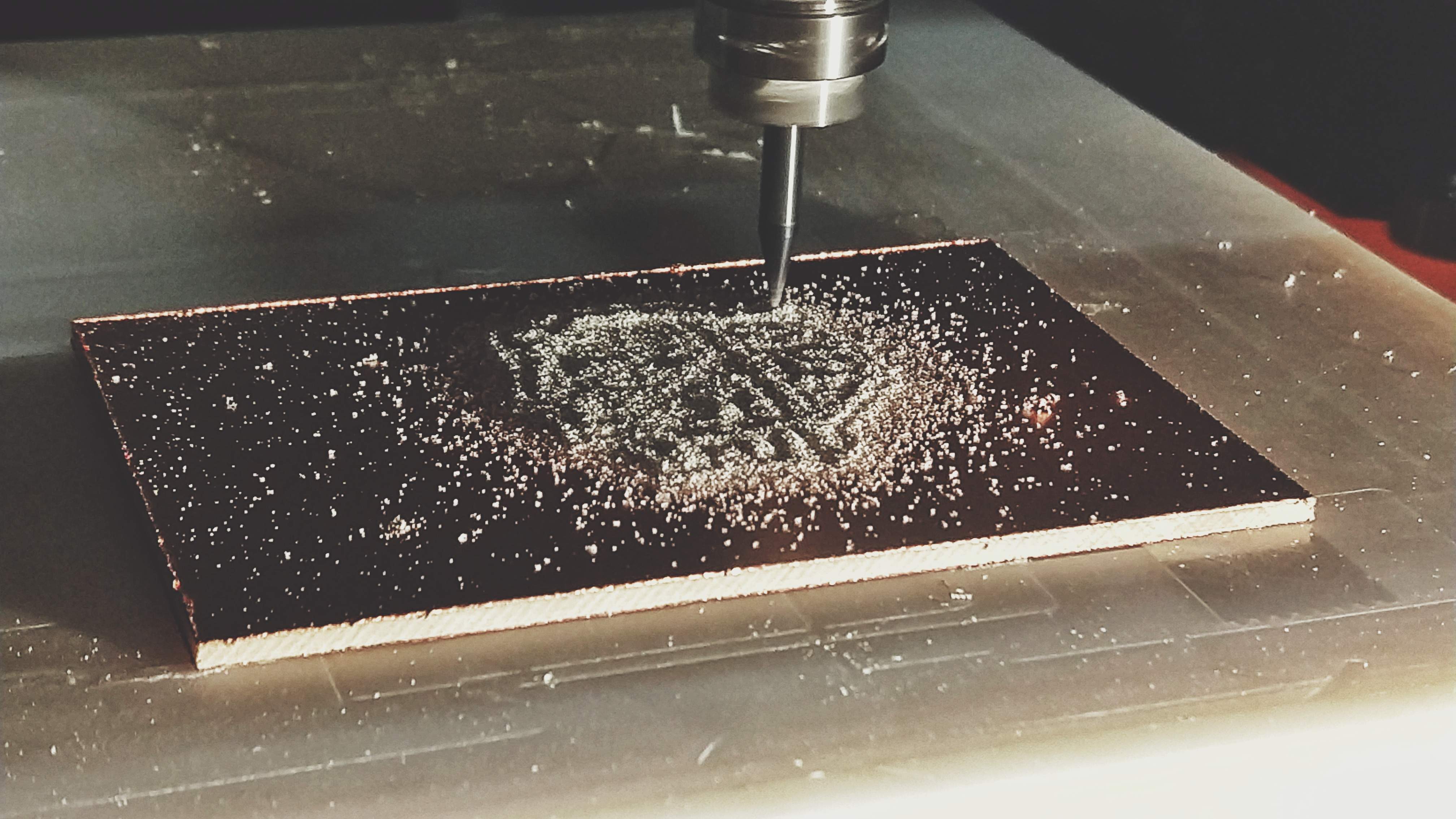
The Milling process.
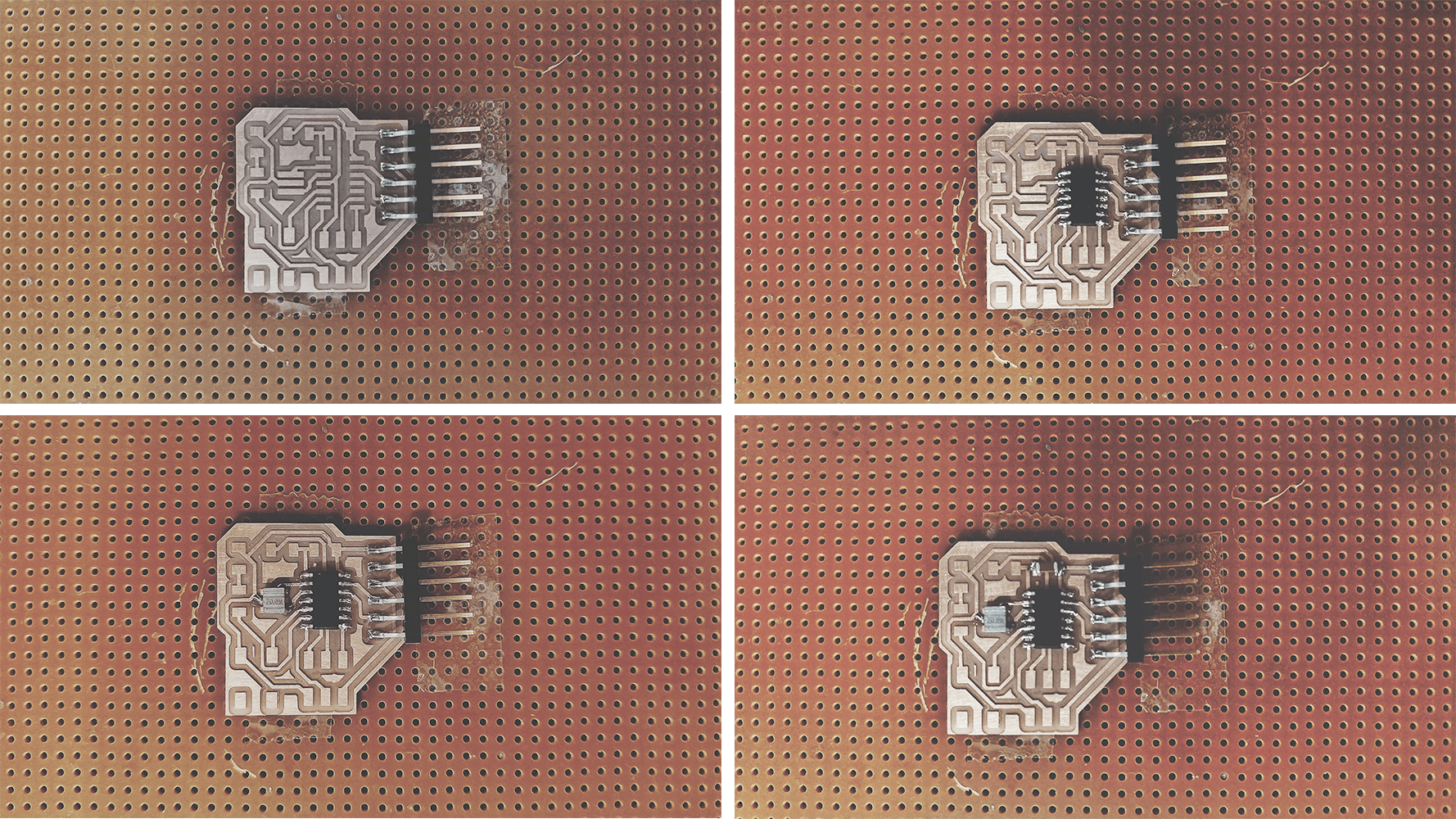
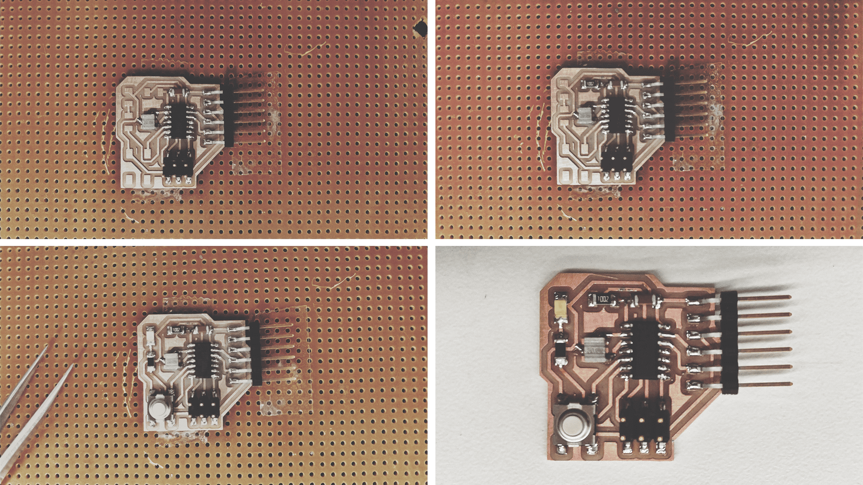
Stages of soldering different parts onto the board. I found braiding to be a wonderful method of getting rid of excess solder and make the board look neat.
Milling to Soldering.
From Drawing to Finished Board.