Week 9
Input Devices
This week's assignment: add a sensor to a microcontroller board that you have designed and read it.
This week, I wanted to start working on my final project - a magic wand! I wanted to use an IMU to measure
acceleration so that I can sense the movements of the wand when a user is waving it. I used the MPU6050 IMU,
which is the one we used in 6.08, so I knew it could sense what I wanted. However, getting it to work with a
microcontroller rather than an ESP32 as in 6.08 was much harder than I expected. I started with Neil's basic
board
for a SAMD11C microcontroller and I added the IMU and a RGB LED (to be used in output devices week).
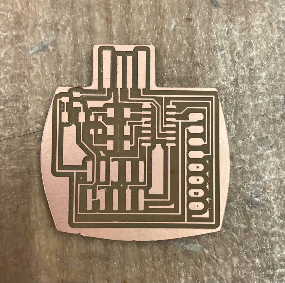
Some of the traces didn't get milled fully because they were too close to each other so I fixed that with an exacto knife.
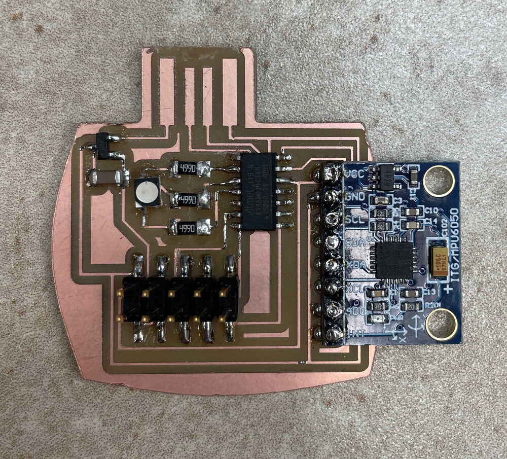
Then I stuffed it as usual, but when I tried to bootload it, nothing connected. After some inspection with
Anthony's help, we realized that I forgot to connect two of the ground pins to ground and the VCC pin to 3V3 on the
5x2 header. I fixed those connections with jumper wires.
But the bootloading still didn't work!!! Upon even more inspection, we realized that I soldered on the SAMD11C on the
wrong way. Pro tip: make sure the dot on the microcontroller is aligned with pin A05 in your design!! So I tried to
un-solder the SAMD11C, but I was in a rush so I didn't do a very good job and when I tried to take it off the board, I
ripped off all the copper.
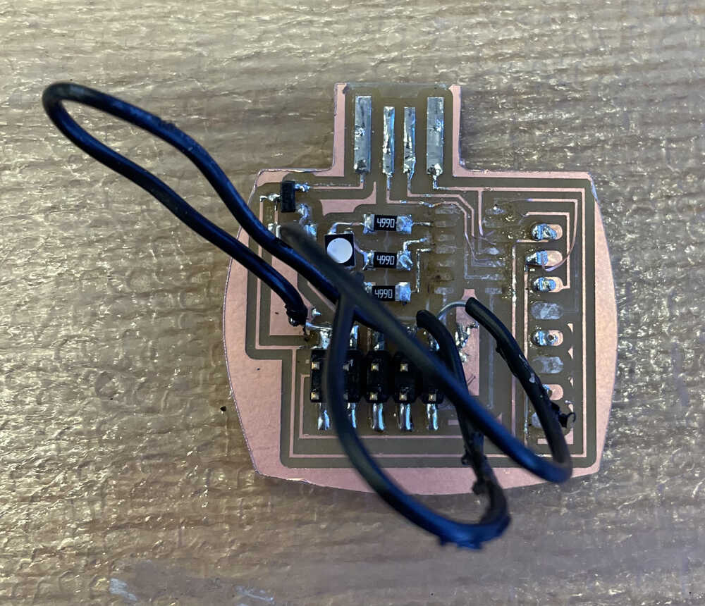
Epic Failure Board
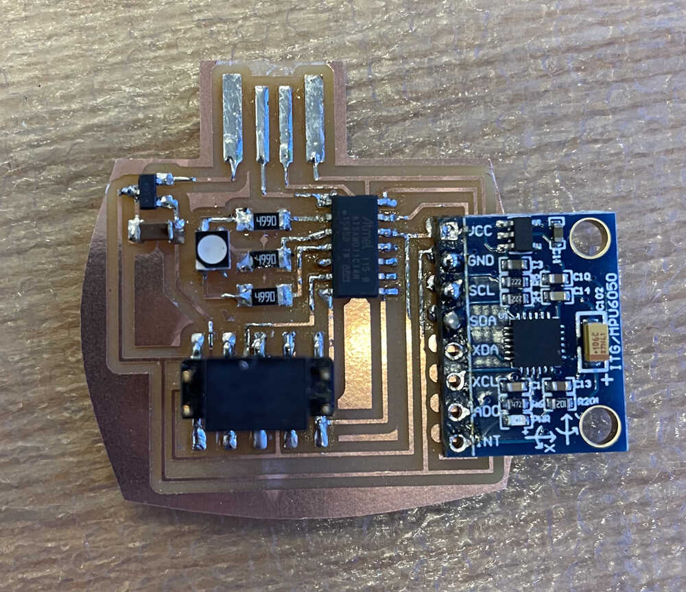
So I started over. I added the connections that I was missing earlier in my design and made sure to solder the SAMD11C
on in the correct orientation this time. The bootloading worked and I was very happy! Next, I tried to program the board
to read the data from the sensor. I found some libraries online that processed the raw input
for you, but when I tried to upload them to the board, I got an error saying that there was not enough memory in the microcontroller
for them. SAD. Anthony told me that the easiest thing to do was to make a new board with the SAMD21E microcontroller.
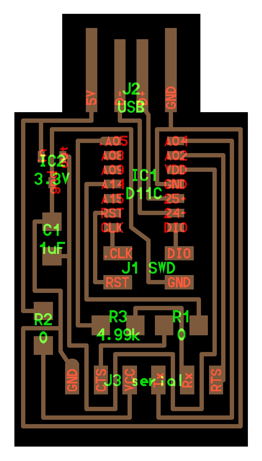
I started with Neil's SAMD21E board
and added my extra components.
The pins on the SAMD21E are insanely close together so it was very hard to solder :'( I messed up a couple of times and had to
redo the boards because my soldering was unfixable. This is also when I realized that there are different thicknesses of the
solder wire... It was so much easier when I used the thinnest solder and I finally got a board that was programmable. I
used the CMSIS-DAP programmer that I made in week 3 to program it (since Anthony wasn't there so I didn't have the ATMEL ICE).
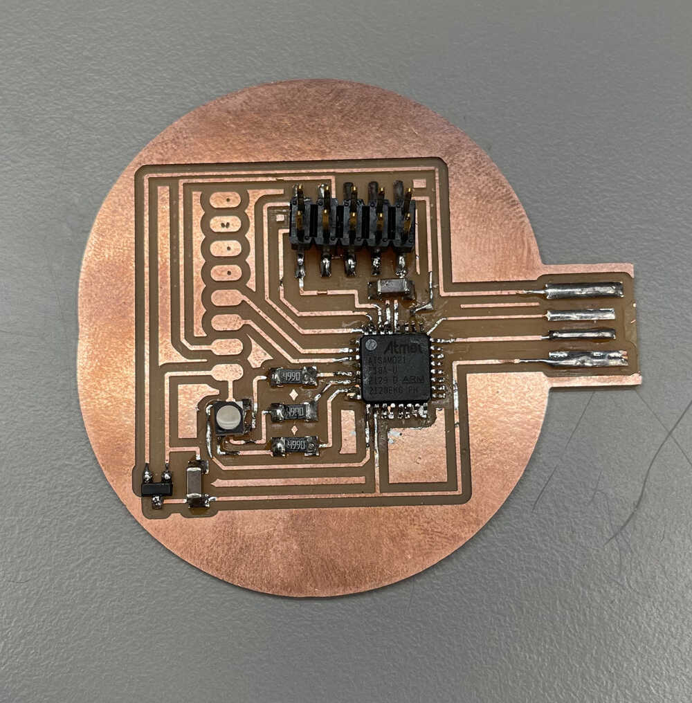
Terrible Soldering
At this point, when I added power to my board, the green light on the IMU turned on, but no data was being detected by the sensor.
Harrison informed me that apparently on the SAMD21E there are specific pins for SCL and SDA so I was supposed to connect the IMU
to those pins and not random ones. Also, apparently you need pullup resistors for those pins as well. Lesson learned: read the
datasheet before trying to use new parts. After fixing that, IT FINALLY WORKED. Using the libraries for the IMU actually still took
up too much storage, so I found some code online that directly read the registers on the sensor to get the raw values and process them
and I modified that.
Here is my board sensing acceleration:
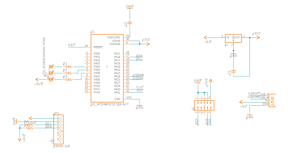
Schematic with Everything Working
I was very sad this week because I had to start over so many times, but I actually learned a lot about electronics and I think I will
have a significantly easier time in the future.