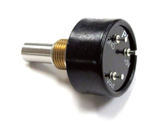
For this weeks assignment, I decided to work towards my final project by figuring out how to read inputs from my encoders. Anthony provided some 12 bit analog encoders that he had on hand. These magnetic encoders have V_in, ground and an analog pin. The voltage from the analog pin varies between 0 and V_in based on the angular position of the shaft. Although these are technically supposed to run off 5V, I tested them on a oscilloscope and it seems like there's no issues running them off 3.3V. Calculating the angle (in degrees) is simply 360*V_out/3.3
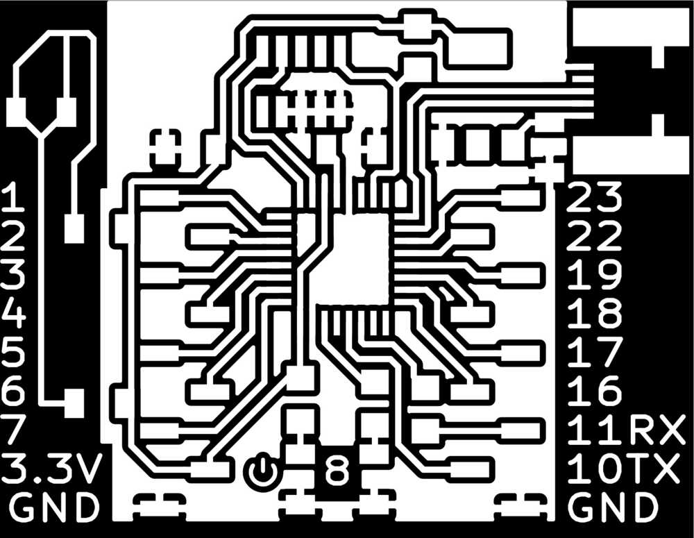
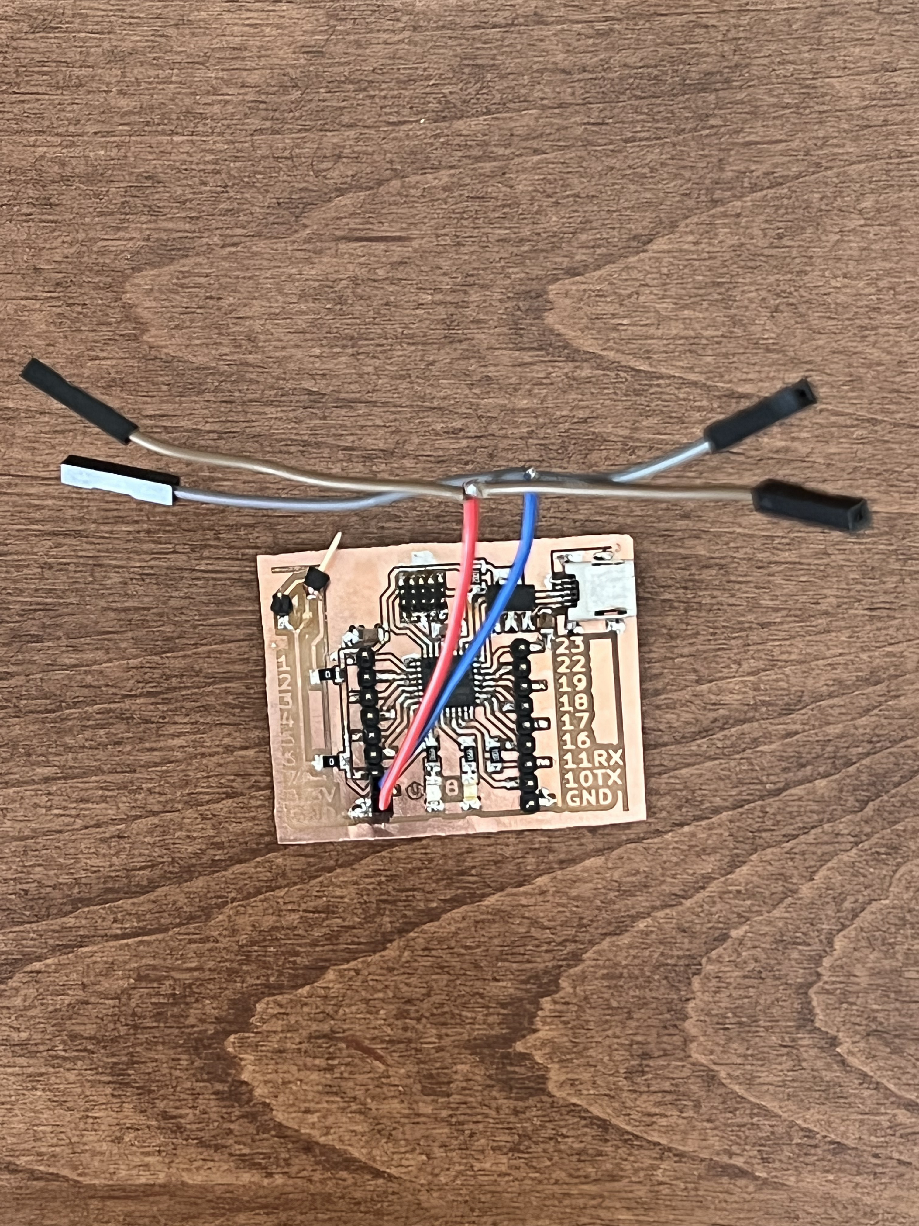
Next, I started designing a board based on Quentin's breakout board for the SAMD21E. I had to reroute some of the traces, add pads, etc. to fit the needs of my hardware.
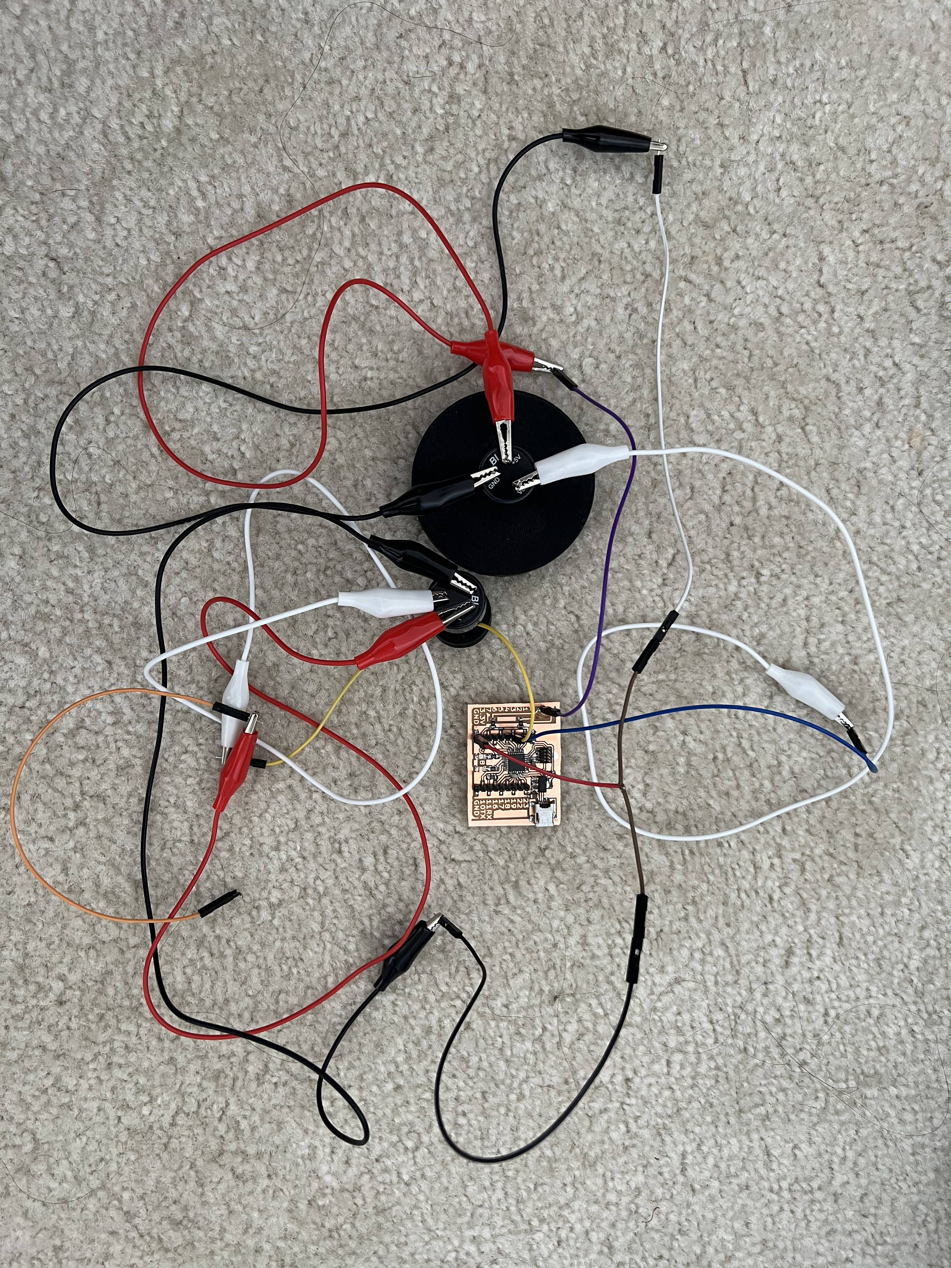
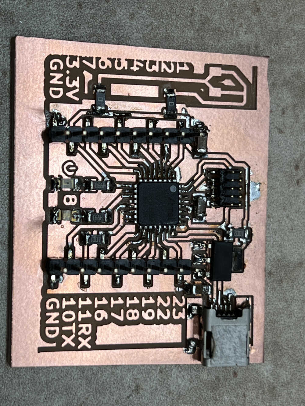
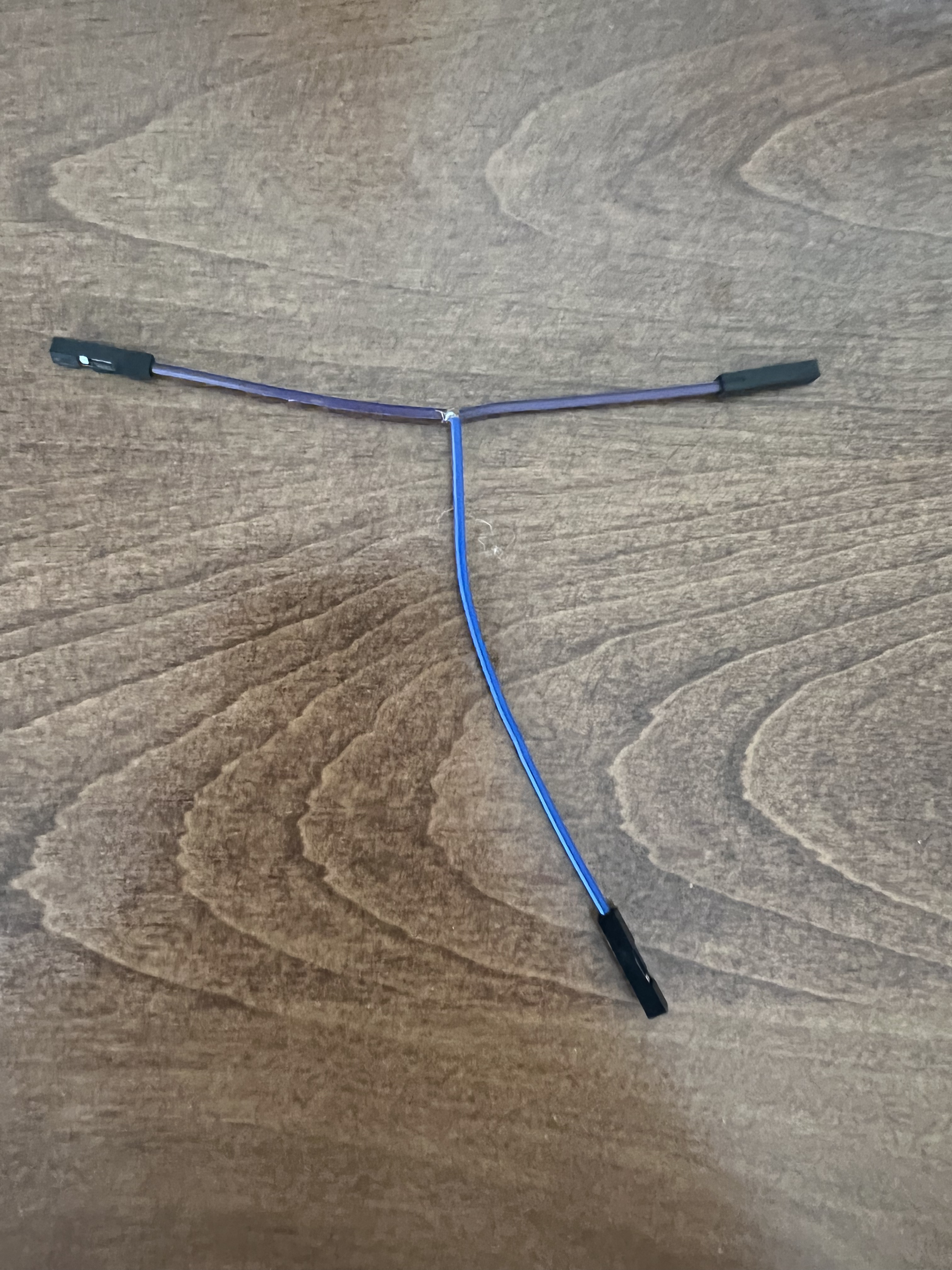
After milling and stuffing the board, I was ready to begin connecting everything. However, I also needed to split some of the headers on my board to allow both the encoders to connect to power and ground, so I had to do a little bit of surgery on the wires. This involved removing the insulation from the middle of one wire, and soldering another wire to that location. It worked pretty well!
Reading the datasheet for the microcontroller, I identified pins 2 and 3 on my board as analog pins.
After hooking up my encoders to power, ground and the correct pins using alligator clips, I ran this code to read the values from the encoder. It worked great!