


About Me

I am a second year Masters in Design Engineer student at Harvard GSD/SEAS. Before coming to Harvard, I studied math and physics in undergrad and then served in Ghana through the US Peace Corps for over 2 years, where I taught STEM and literacy and led numerous projects in agriculture, construction and gender equity. Since coming to Harvard, I have dabbled in data science & AI4SG, structural color, EdTech, game development and most recently extragalactic astronomy and cosmology. I like making stuff and learning stuff. Here is my portfolio if u curious LINK.
Final Project Ideas
Here is a brief overview of some project ideas from week 0:
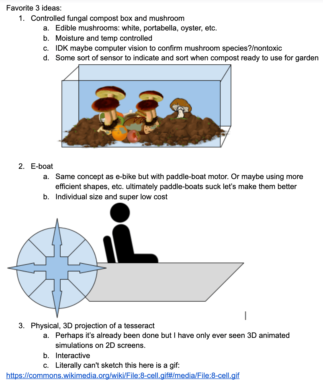
Here is the link to the dynamic 3D projection of 4D "cube" LINK
Thoughts on 13. October
I really want to make a motorized vehicle because I never have before. But what kind? hmmmmm Call me crazy but it astounds me sometimes that we still have not figured out how to make personal flying devices. So probably gonna explore that a bit. So far, some rabbit holes I've gone down:
Leaning mostly towards hydrogen--Hindenburg gave it a bad rap.
Drones just do not seem efficient nor easy to manuver
Will start sketches this week once I have any sort of clear direction
Thoughts on 19. October/ok this is my offish final project idea
So, after extensive research. A personal flying machine does not seem possible to fabricte in the given timeframe. In the meantime, I have designed an affordable, eco-friendly motorized + human powered water vessel.
Imagine jet ski + bike + ebike + paddle boat.
Water Bikes
Don't you hate how all the inexpensive aquatic vehicles (kayaks, canoes, etc. focus on exercising you rarms and core rather than your legs? What if it's leg day but you are in a boating mood?
Another thing. Aren't jet skis bad for the environment, polluting water, etc.? Well now there's a waterbike. Or at least hopefully there will be:
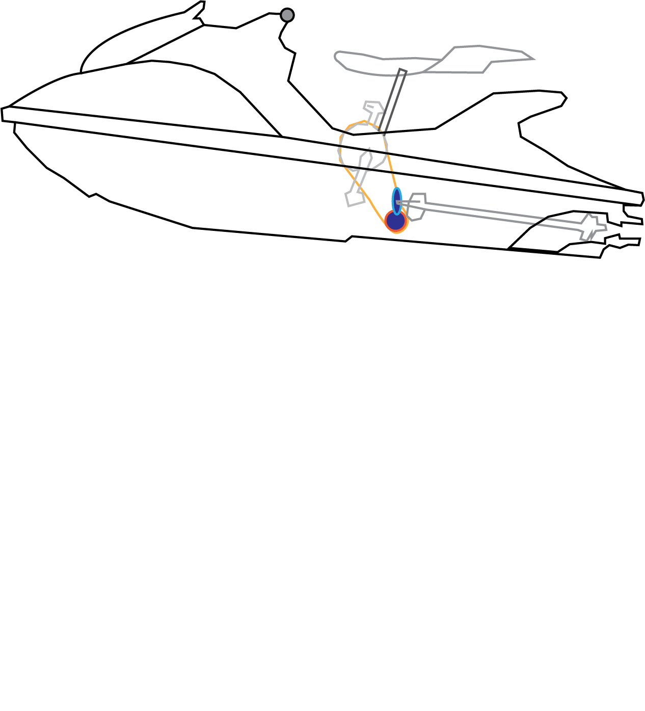
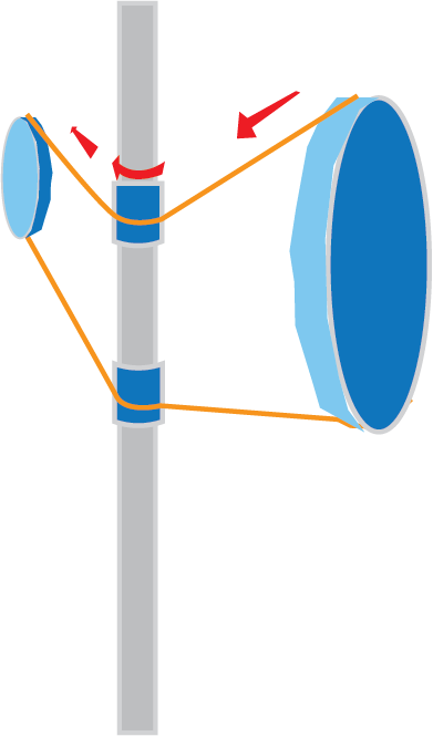
This idea is a HUGE step up from paddle boats, which is the closest comparison. Paddle boats don't utilize the efficient motor design of other boats, because it would require changing the axis of rotation. But I have a few ideas of how to do so.
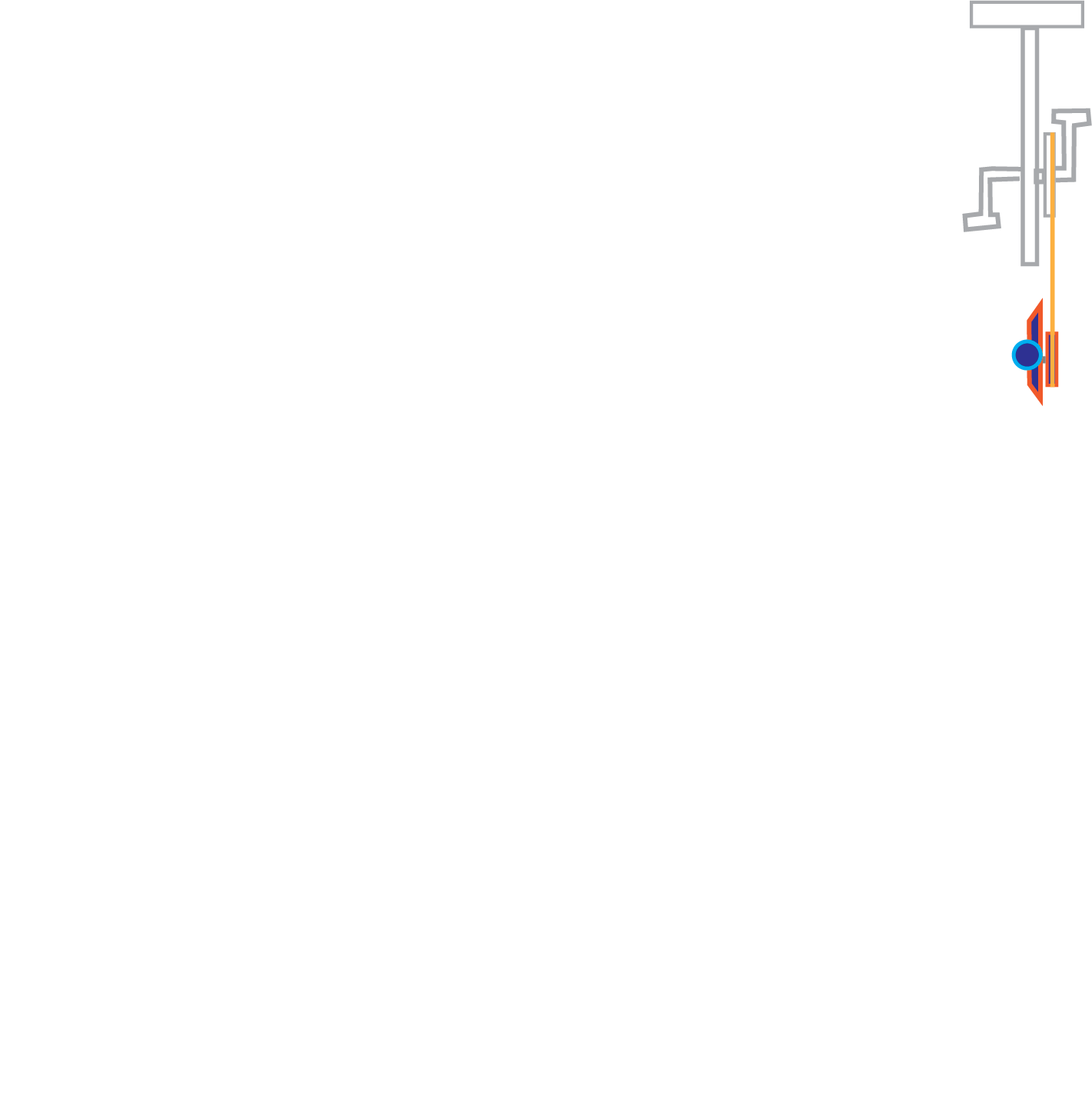
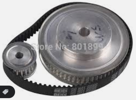
One idea is to utilize a bevel gear, which uses notches in gears set at an angle to change the direction.

Another idea is to use rivet-washer-bobbin things to "catch the chain" and spin with it in the other direction. I am sure this idea exists but I am having trouble finding it.
End goal is to also attach an e-bike motor
Pivot: Tangie
It's cold and waterbikes exist
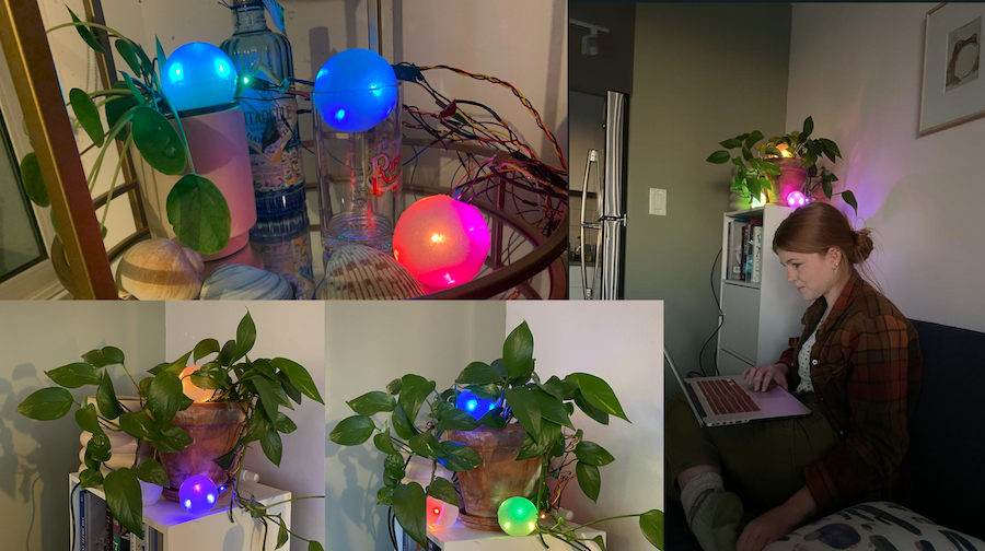
The weather is getting cold and imagining myself testdriving a waterbike seems laughable at this point. However, I do need to make a squeezable/lightup ball network for tangible interfaces so maybe I'll just do that.
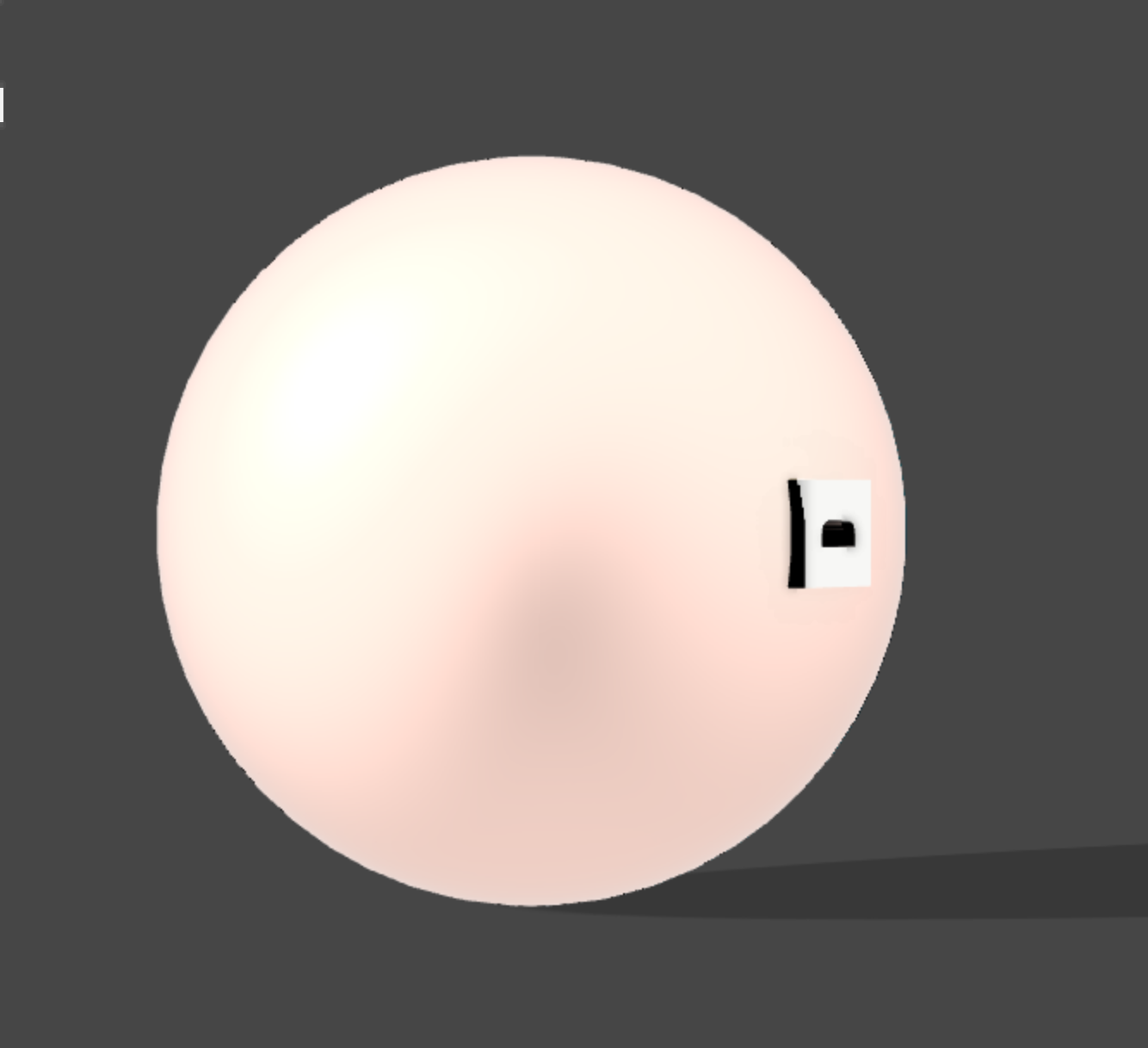
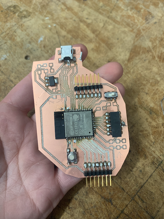
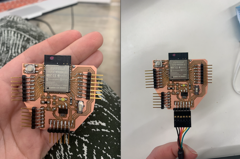
See these pages: this page (w8) and especially to see that I have completed the electronics component for a final project, please see here: this page(w13) for major updates.
On this page(w13), you will see that the tangie project, in which I did all of the electronics, offered a good precedent for BeatBox. I sent Kels my code and schematics for ESP board so that she could remake and build off of it for our project. However, after some tests, we realized it would be better to use her old SAMD11 (in which she had required resistors already built in) and use velostat, which could be used over a larger area and was more flexible (could take a punch better).
Pivot: help Kelsey
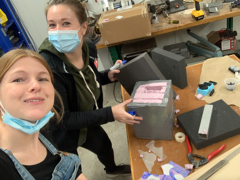
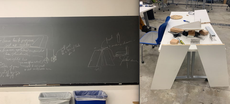
Wanting to do more than just improve a squishy ball, I decided to also help Kelsey with hers: making a DDR-type device for martial arts. We had already been discussing working together, and she needed help with the mechanics (something I am actually good at comparede to electronics) so I decided for my final project to take charge of the structural/track portion while Kelsey would stick with the light-up tombstone. I learned we had a slotted steal channel, belts and belt gears as well as rotary bearings, so over break I did some 3D modeling:
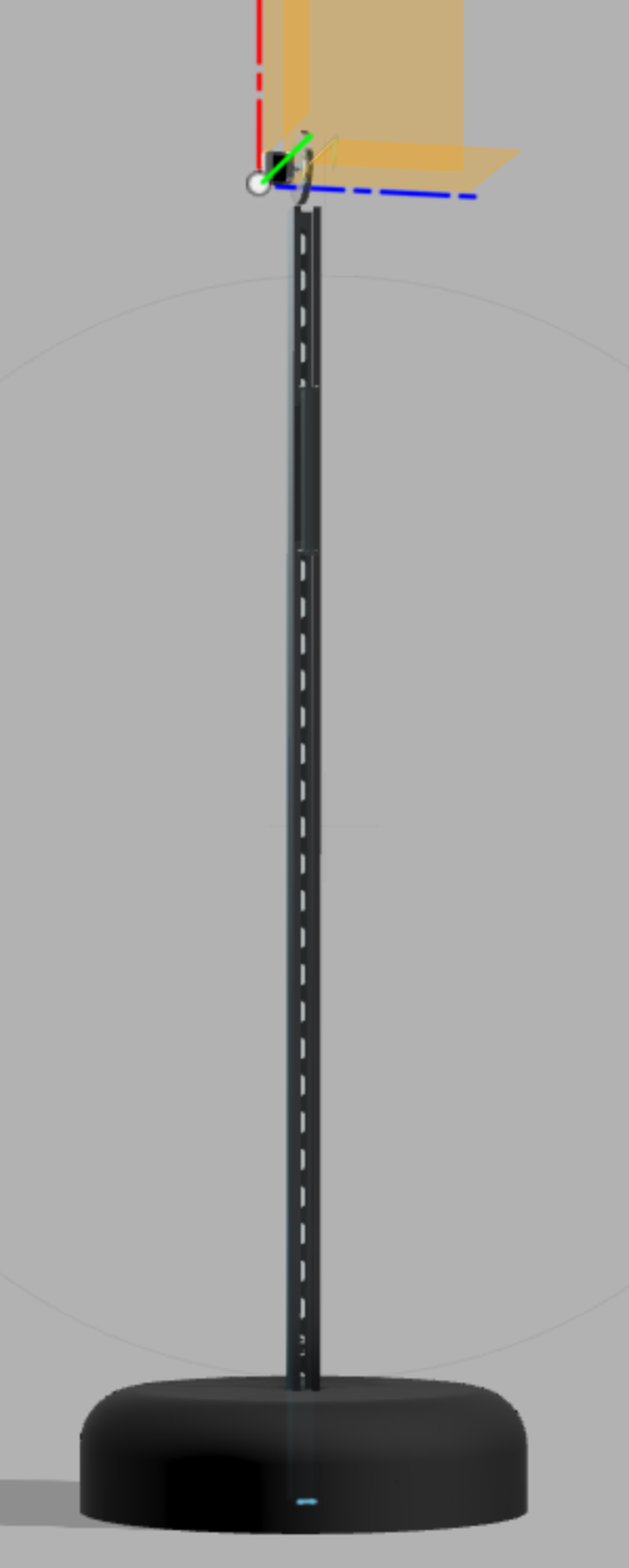
And started to plan how this would work. The belt/motor/gear things are pretty straightforward. I think using a large gear/pulley thing on top would where the motor is would be ideal to maximize speed (translating rotational to linear motion highest the larger the radius)
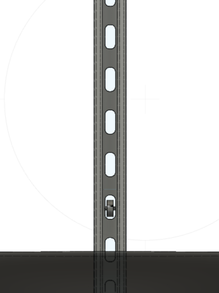
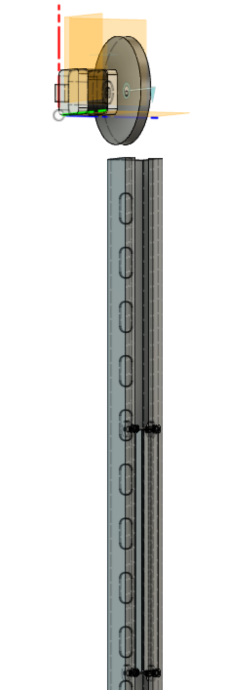
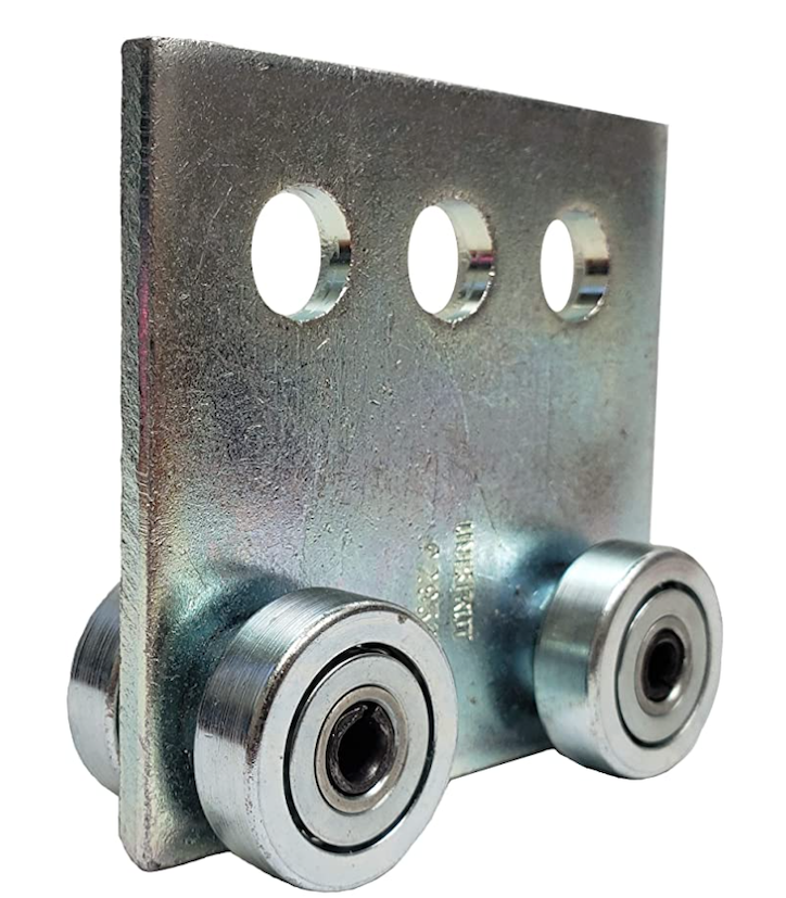
As for the cart, most examples for slotted channel trolleys were for horizontal motion (so the load applied a downward force perp to opening). Therefore, I worried that the vertical orientation would add complications to alignment with gravity no longer acting to stabilize. The examples online:
Adjusted and fit into 3D model (lengthened to take impact better):
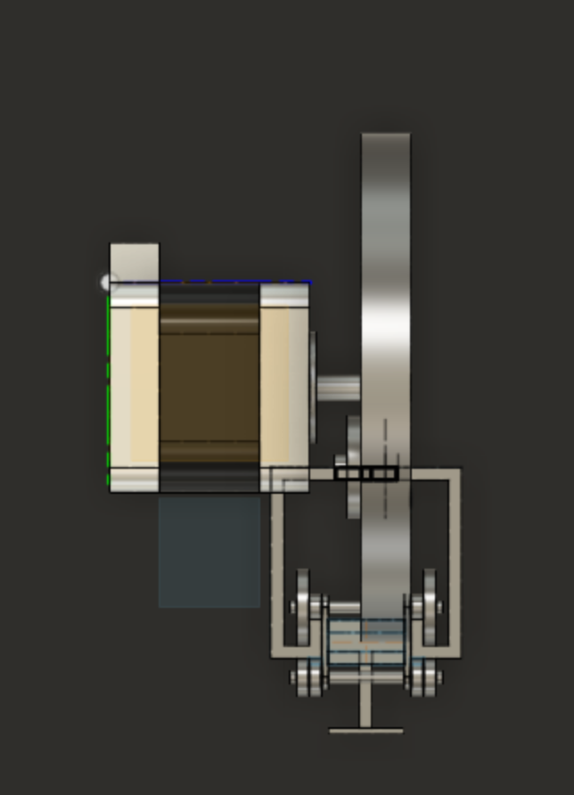
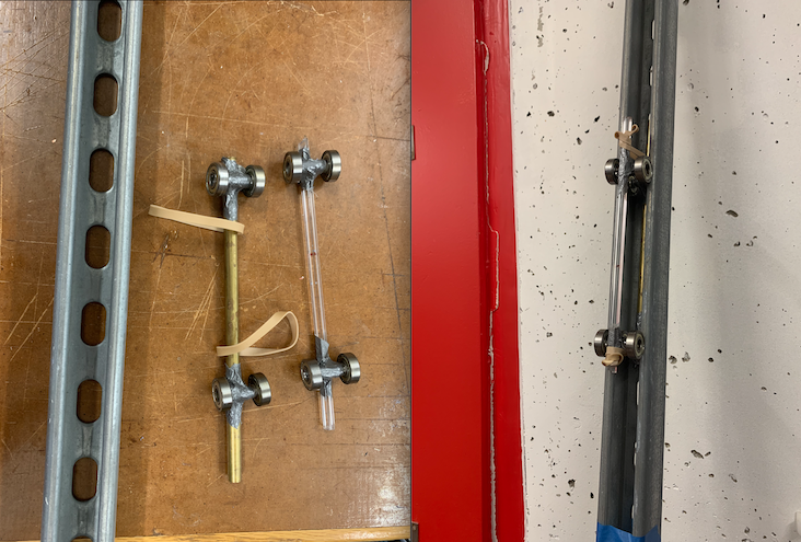
So, wanting to test quickly, I used the materials available to make a makeshift trolley. Those materials include: casing for aluminum rod (nothing else fit snuggly) standard rotary bearings ductape, rods of different metals and rubber bands
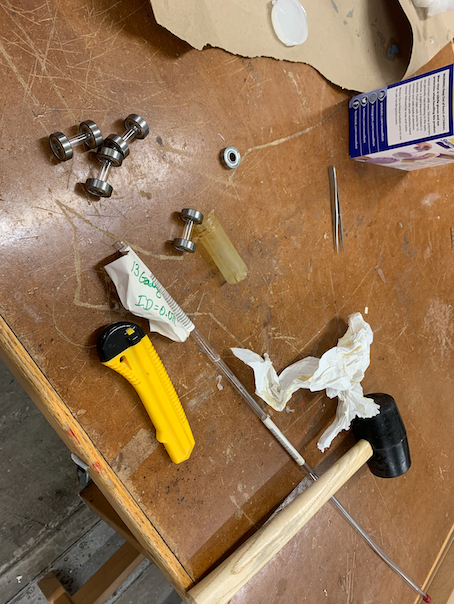
From this test it was very clear I needed bearings with grooves/ridges to keep the trolley aligned with track
THE BASE IS SOMETHING I am definitely a bit worried about-- but will probably just mold over an existing base, like the type used for a standalone boxing stand, and then cast it in that (whatever it will be) then, if necessary, secure it onto a wide, wooden board or something. Planning to wing that part a bit..
MOST RECENT UPDATES, please see WEEK 13 (end) and scroll down a bit
PRIORITIES LIST
- Cube
- - widen hole in styrofoam for box
- - add capacitors - (based on which setup works best ppc or velostat)
- - hook up board and test pressure with foam
- - add foam
- - hook up LEDs
- - cover w/ vinyl
- - tweek program
- - glue in aluminum box/finish assembly
- Track
- - trolley attachment to box
- - trolley
- - stand/base
- - mobility
- - assemble: belt-trolley-pulleys-step motor to track
- - step motor electronic setup
- - step motor program
- - connect boards
- Application/interface
- Make super simple interface - (choose hard, medium, easy, beginner mode)
Final Crunch
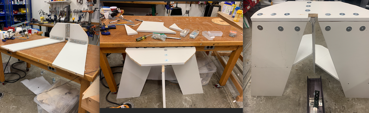
Gluing
I guess it was inded ok to undo the ducttape. When life gives you no clamps of the right size, make clamps.
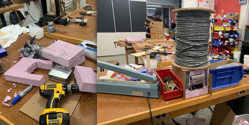
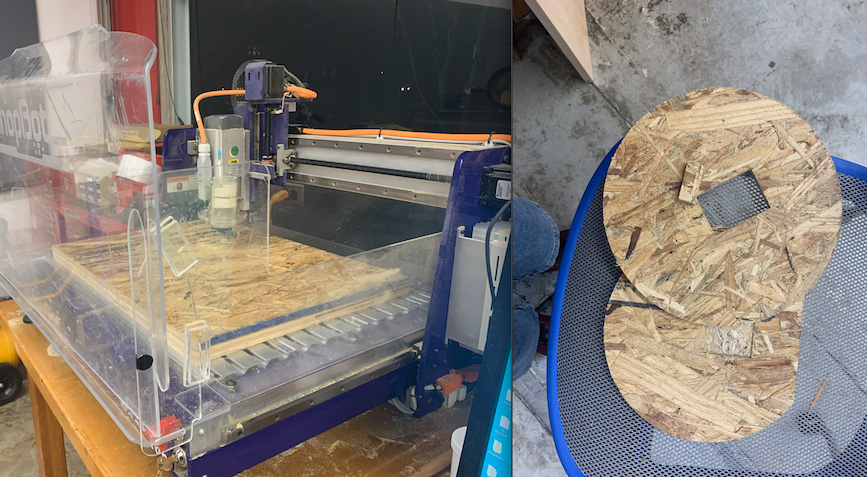
I attempted to mill a stand, starting with 2 circles, one with a pocket one with a hole, but realized the stand needed to be much heftier than small, layered circles of wood.
The next attempt to make a stand worked fairly well as a temporary solution, but was not stable. I found a super heavy base and cut some aluminum to secure the steel channel, which was secured onto a steel corner thing (green thing on left image below), but, as one might guess, there was too much freedom of movement.
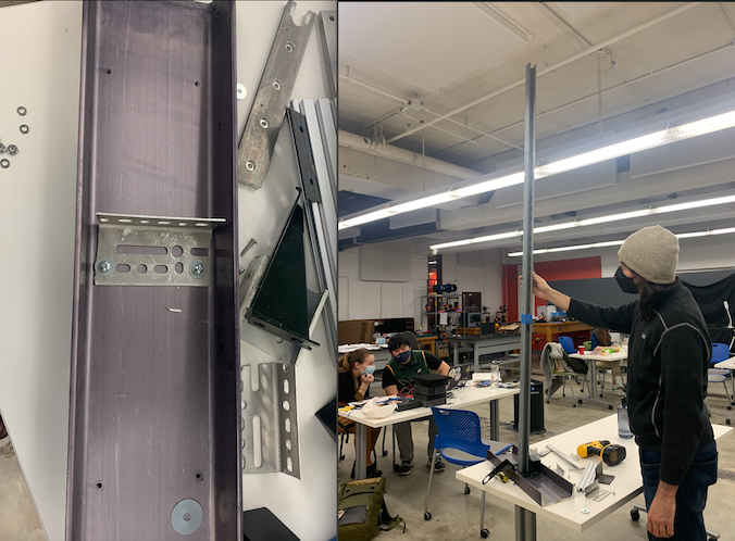
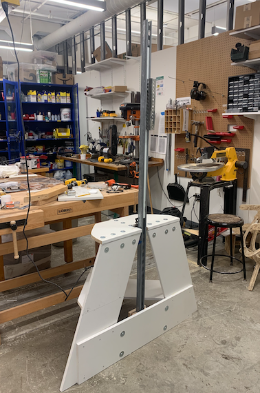
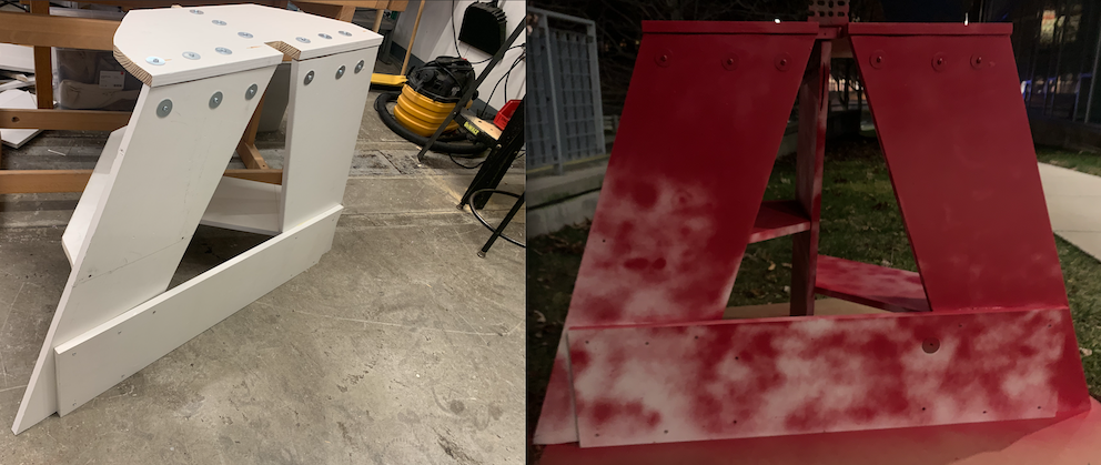
It getting later and later in the last week, I needed to figure out the stand ASAP so that I could work on the rest of the components. I wrote out all the possible solutions (left, image below) and settled on what I thought was the simplest solution--using structural support that could easily have weight added at the base. Using wood from some discarded shelves, I used a squirrel saw to cut the three supporting boards (for sides and back, not front as that would make user trip) at a 72 degree angle to a height that Kels and I determined the lowest setting could be for the cube. This would have also been milled but only the upstairs shopbot was open and these boards were too large.
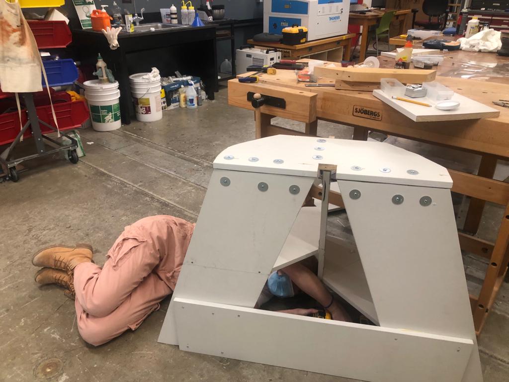
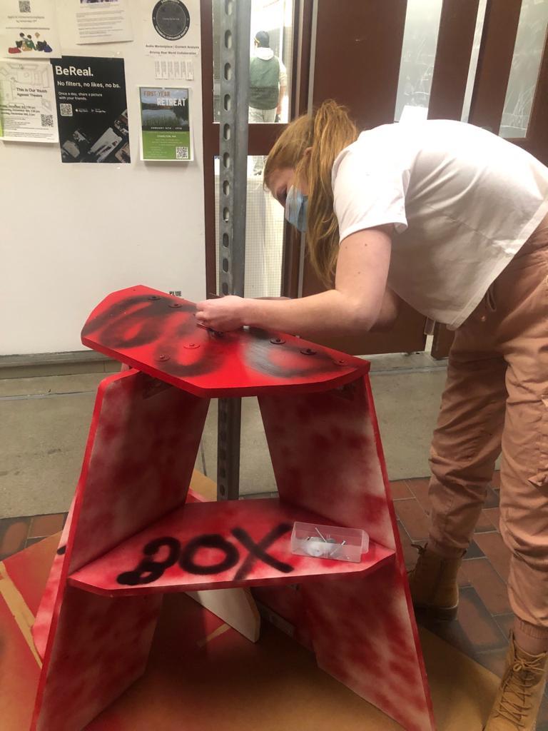
Not finding any screws, I painstakingly used nuts and bolts to secure the top piece using more aluminum that needed to be cut by hand. A little while later, I learned that we indeed had screws and nails, so for the lower supports/shelves for boxing gloves or weight to add, I used screws like a sane person. The structure was a great start to hold something that could take punches.
The original plan to have a trolley conencting the cube to channel seemed impossible (based on previous tests and logic) to make in a way that both rolled smoothly within the channel and would maintain its track while experiencing a significant amount of force in all directions. Moreover, after some user testing with the foam box, it didn't make sense to have it constantly moving up and down in addition to the randomized lights, and more sense to have it set at chest-nose height of the user so they could see which side was lit. After some discussion with Kels and reflecting on the last class in which we were told to focus on having a "nice finished product," we decided to make a finished product that could take serious hits, be easy to adjust for each user, and easy to assemble/disasemble rather than add a bunch of stuff just to hit the 2 sets of electronics requirement.
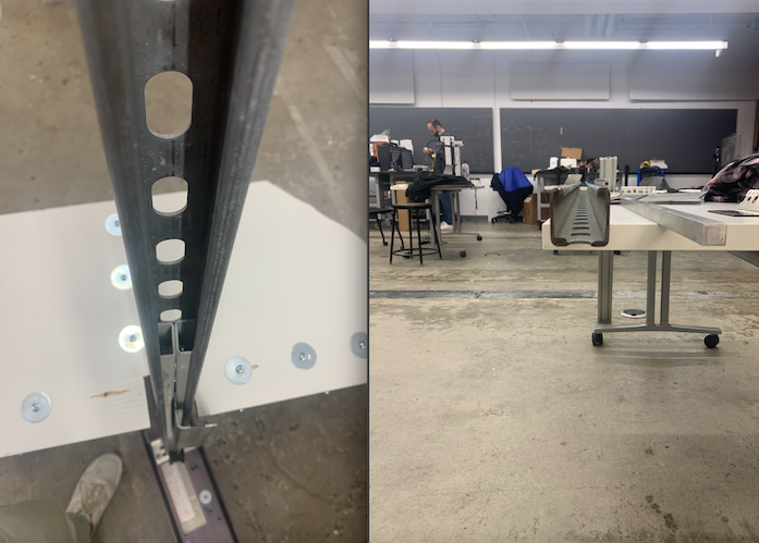
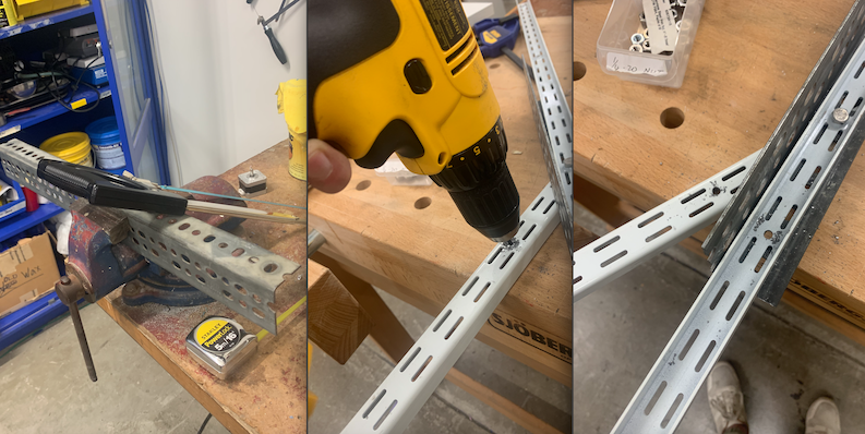
Thus, I searched for metalic solution to connect the cube to the track, seeing what could possibly fit and secure an extrusion for the cube. It ended up needing to be inwardly hollow so that it could fit a steel extrusion between and be secured with nuts and bolts without affecting the motion within the track. This required a significant amount of sawing and drilling steel, something I have never tried before and hope never to do again :). But it worked!
The next step was to make an easily removable connection on the base of the track to connect with the stand. So, I added a board to front of the stand, and created an attachment on the base of the track secured to two thick, aluminum rods that could easily be bolted into the front board of the stand.
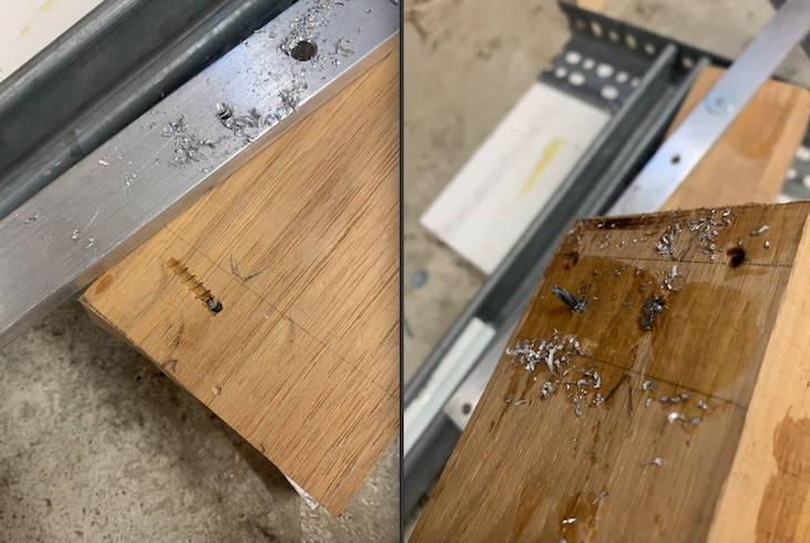
The first attempt to make the track attachment used 2 blocks of wood that deserve a shoutout for eating/breaking 5 screws and a nail, harder to drill than steel. Obviously used different wood after the sixth failed try to insert between the back board and aluminum around the track.
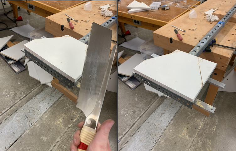
To improve the ease of inserting this base into the stand, I had to cut part of the back board off which was super fun due to using a new tool: the Japanese pull-saw. I want one.
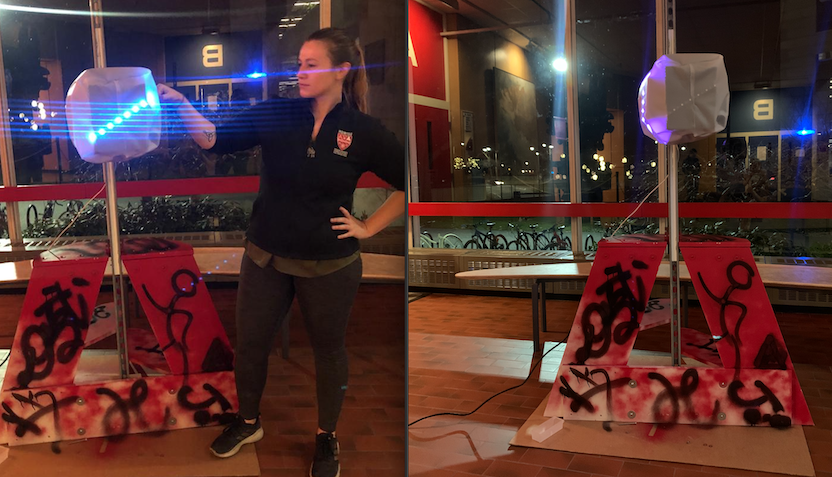
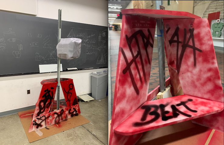
Finally, the structure was done. I added a small steal attachment to the top of the stand to bolt the back of the track there as well, which didn't affect the movement of the cube attachment at all, perfect!
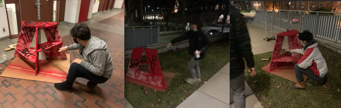
But now it didn't look clean, so I sanded all the edges and decided to spray paint it red (a lot of things in krav maga are red and black but I was in a red mood). Unfortunately, during my second coat, the red spray paint ran out.
As I started painting it black instead (we had a lot of black spray paint), I had an idea--maybe everyone in the lab can sign it and it gives it more of a "street art" vibe. This was super fun and it was great to see everyone add something new--a picture, a name (even one in Chinese letters), a symbol, etc.
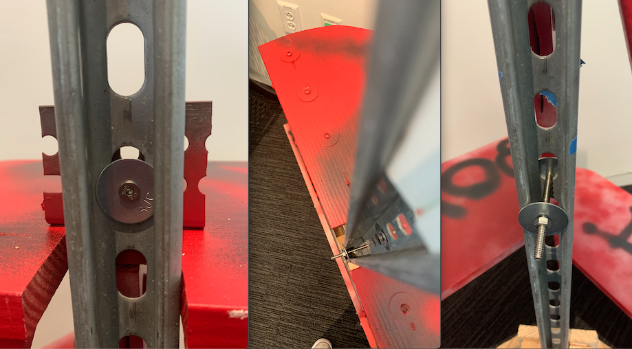
After adding the cube, it seemed the bolt that connected the track to the top of the stand now impeded the path of the cube attachment with the added weight changing the angle slightly, so I found (after much searching) a flathead bolt that worked nicely.
The flathead bolt is shown below, as well as the simple nut-bolt-washer solution used to set the height of the cube.
All done
We both/each attempted to add an interface that would tell you how many hits you got in a minute, etc. but could not figure it out in time as we were deleriously exhausted.
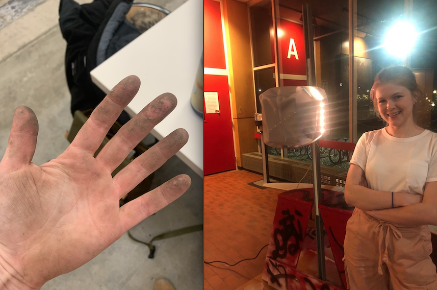
My hands are absolute crap now, full of glue, metal dust and splinters, and will be until my skin cells regenerate but wouldn't change a thing.
Finally, we filmed a video which I edited.
After the showcase, the BeatBox moved to the first-year MDE studio in SEC.