Starting out optimistically, I had a grand vision of creating a board with which a user could push buttons around a unit circle that would make the sine, cosine, and tangent lines light up to help middle school - aged children understand trigonometry conceptually. Remembering my failure week 1, I reduced this vision to a board with 26 letter buttons that would make an LED blink in morse code. By the time I started KiCad, this vision reduced to a simple board with the minimal required functionality--just a working LED and button.
KiCad Confusion
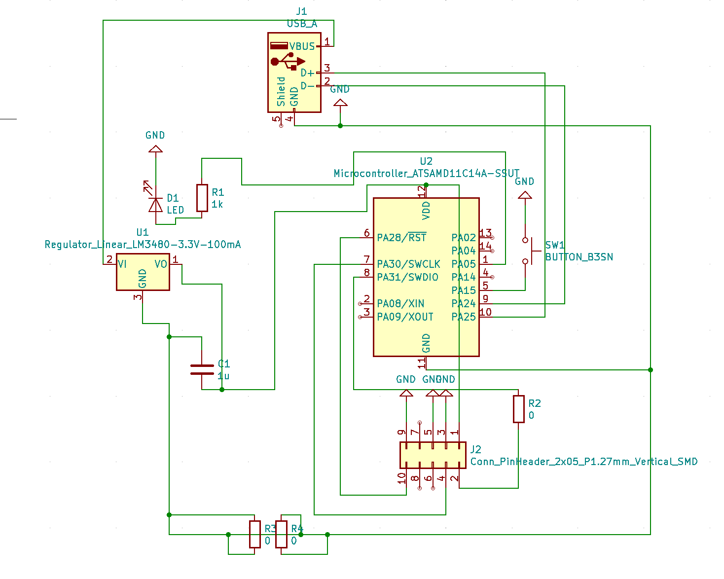
The recitation recordings were very helpful in intorducing the KiCad software, but did not clarify some key aspects of the assignment.
Some issues that needed resolving include adding the USB footprint to the fab.pretty library, figuring out how to add a button and LED, and understanding how to translate the echo board symbols into footprint names. Eventually though, the schematic came together with some help from peers and Nathan.
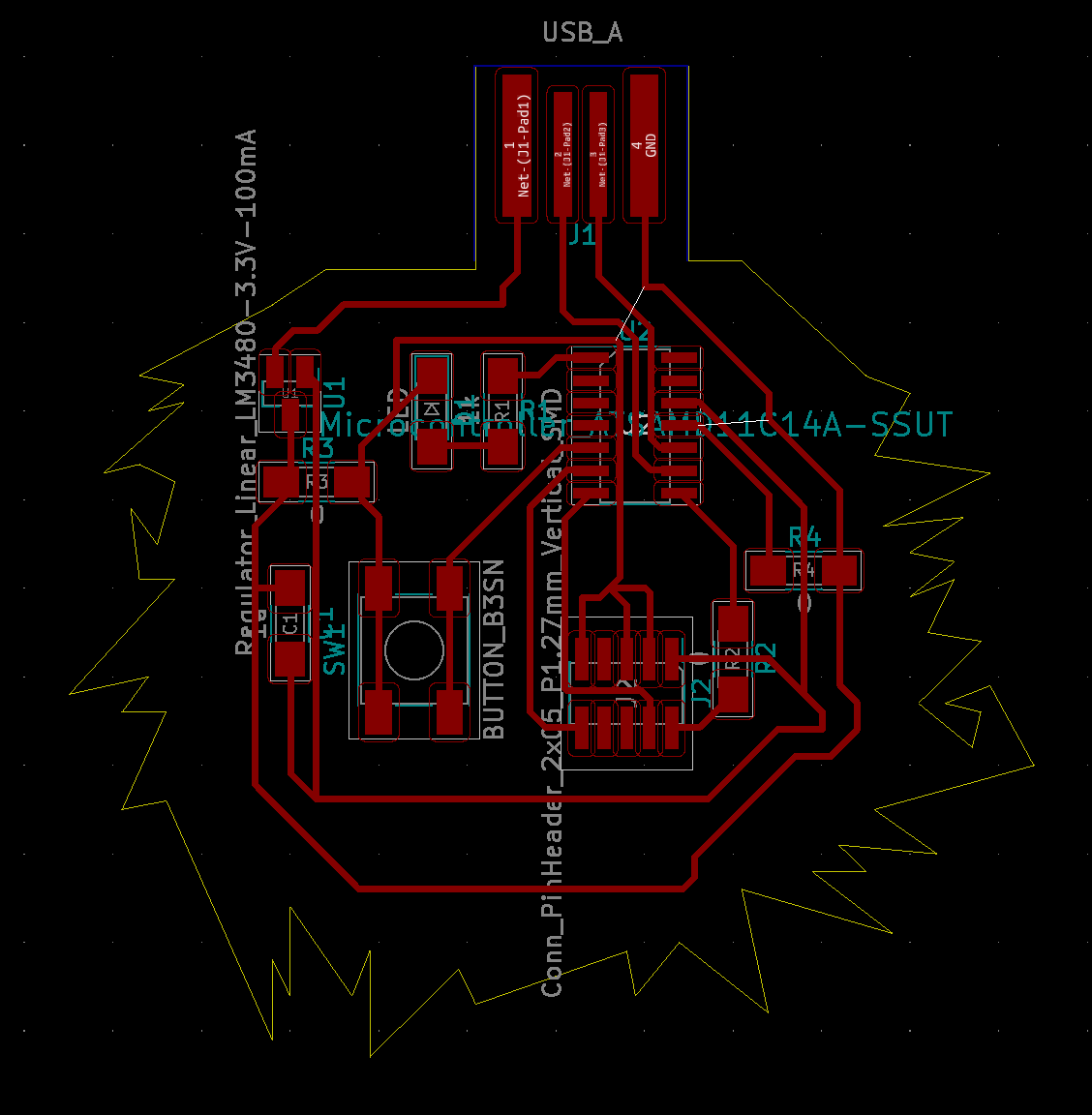
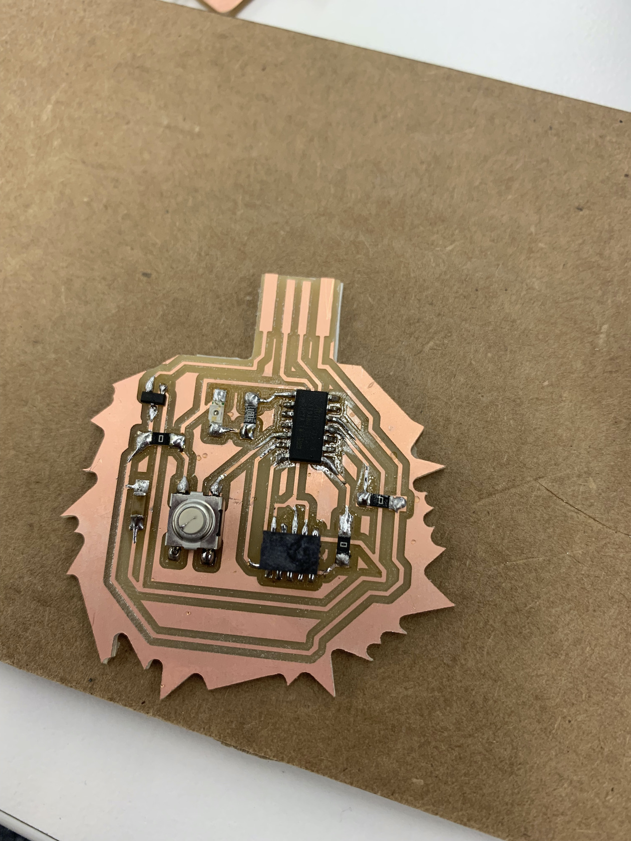
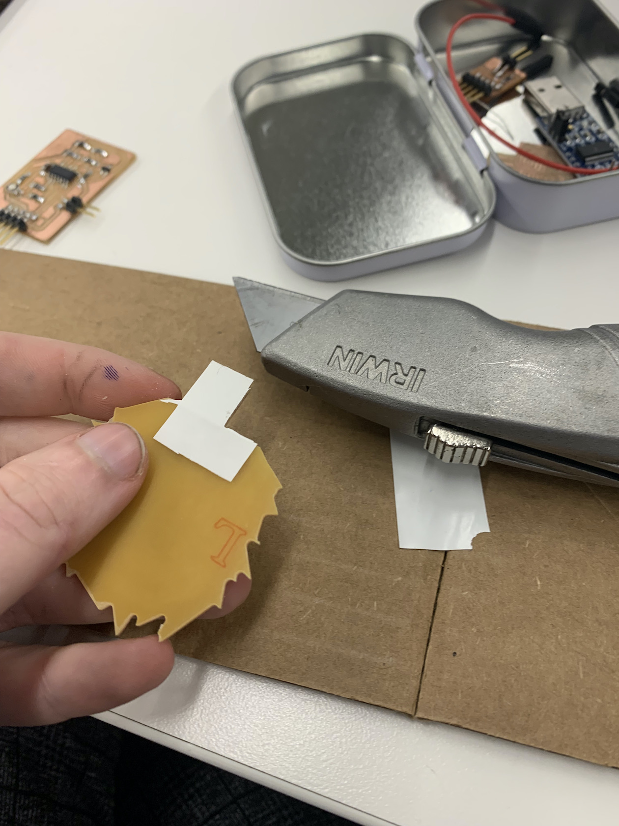
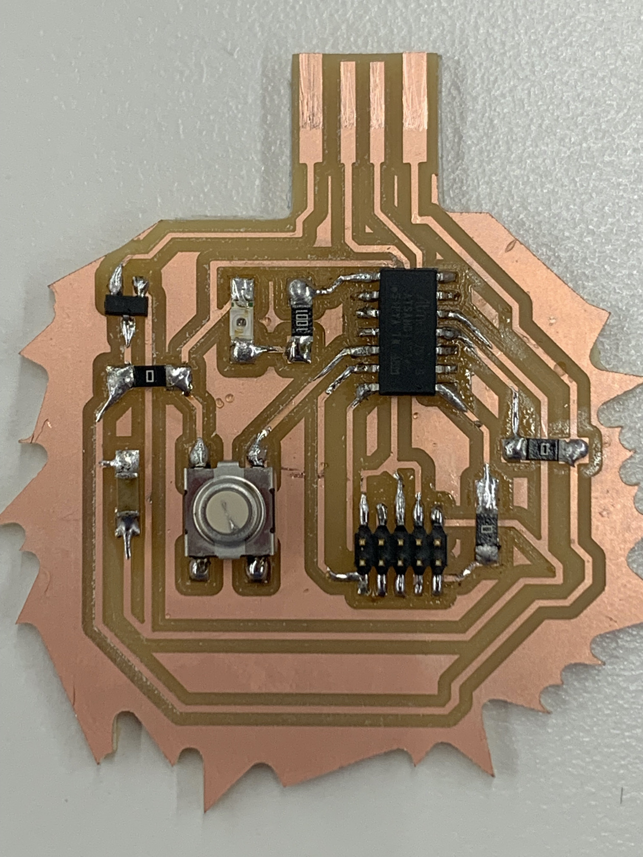
In the PCB layout editor, a few adjustments had to be made in order to make the circuit work, mostly by adding 0-Ohm resistors. I evenually got it, but the process was frustrating enough that I was inspired to make the edge-cuts into an "angry board." The board shown below was redrawn to make the spaces between the traces larger after several failed milling attempts explained in the next section. I learned it was not enough simply to enter the necessary parameters into the board setup.
Milling Mayhem
Day 1
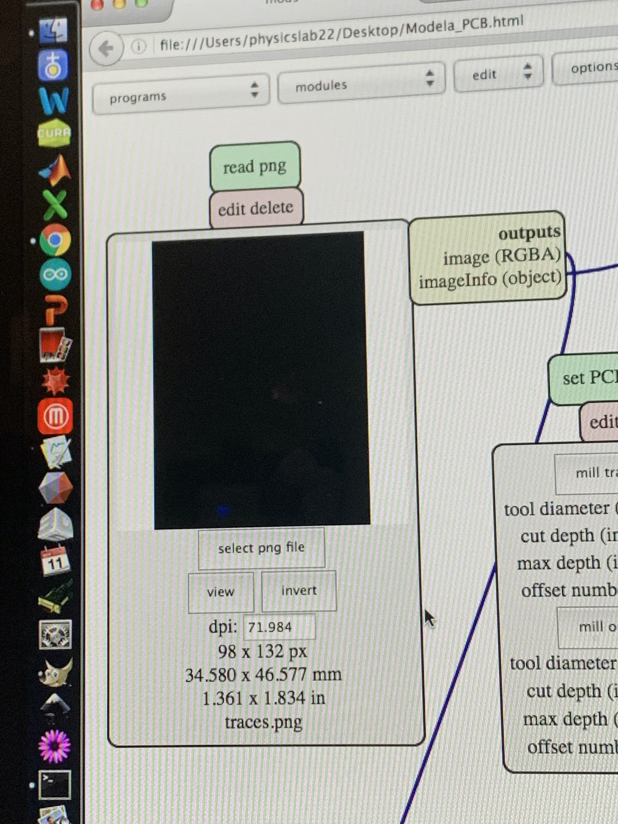
With an optimistic start, the first issue arose when the exported png resulted in an inverted image shown below.
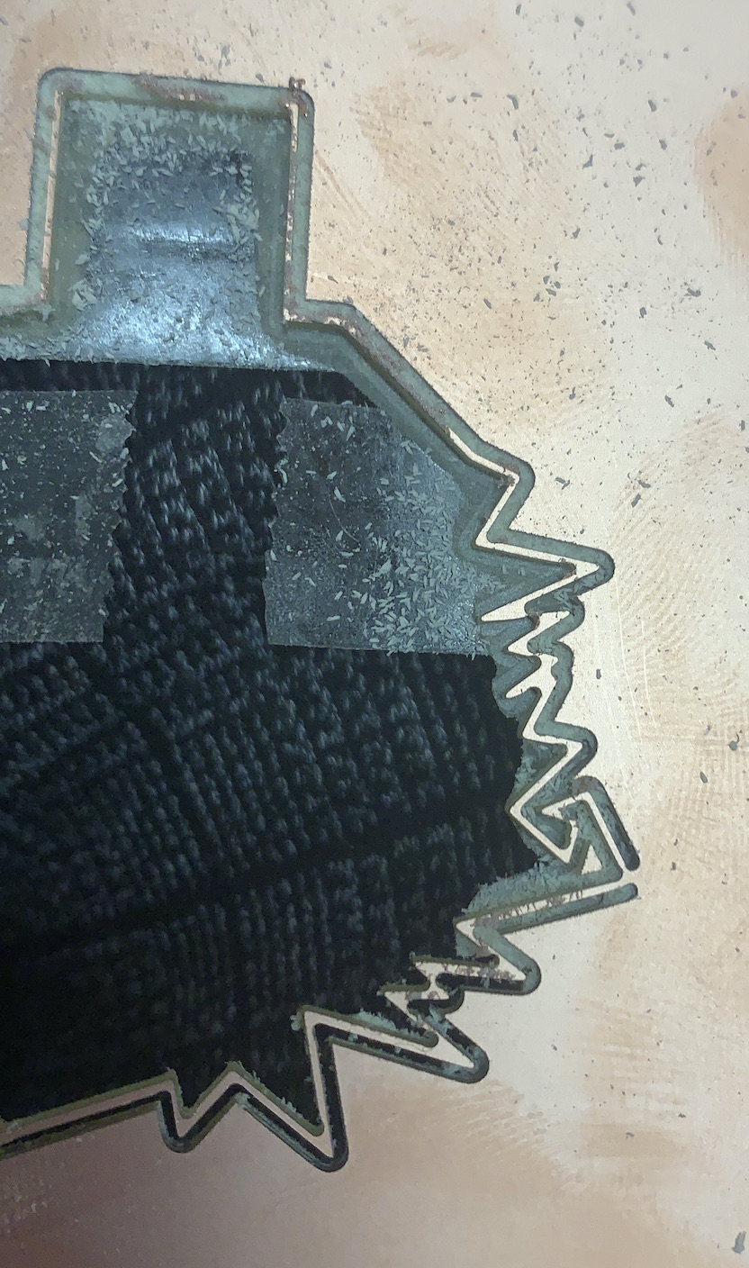
With even less luck with svg format, I used Inkscape to invert the trace and the interior, and made sure everything was in the correct dimensions. Unfortunately, 2 attempted boards later, I realized there were 2 major flaws.
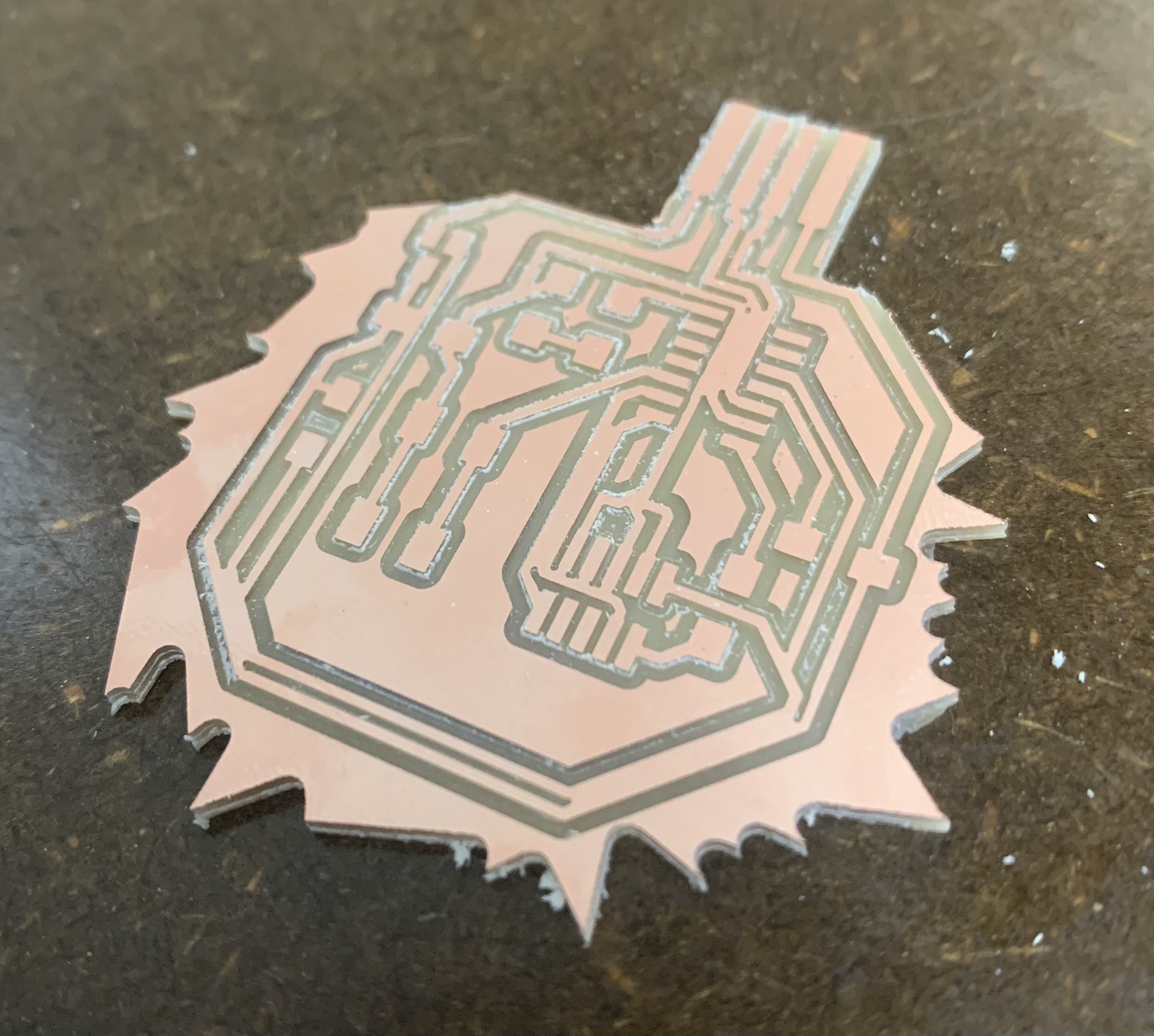
1. The PCB layout somehow did not space the lines enough and they ran together (clearest on bottom right of image below)
2. The inverted interior trace was not blocked out, so it milled around the border on either side rather than the outside. Oops.
It being 1:30 in the morning, I decided to call it a night and try again the following day.
Day 2
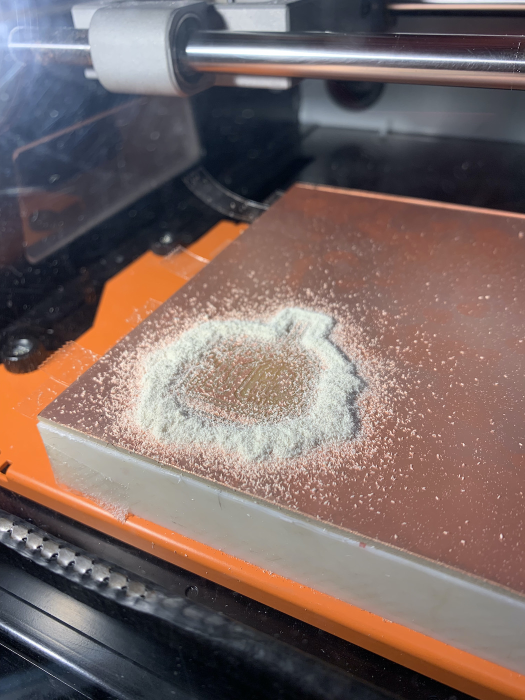
With the help of peers, the next day went much better. I had help getting the border correct with Inkscape and, after a few tries getting the right depth (as per usual) had a promising white dust on the plate. HOLD YOUR BREATH
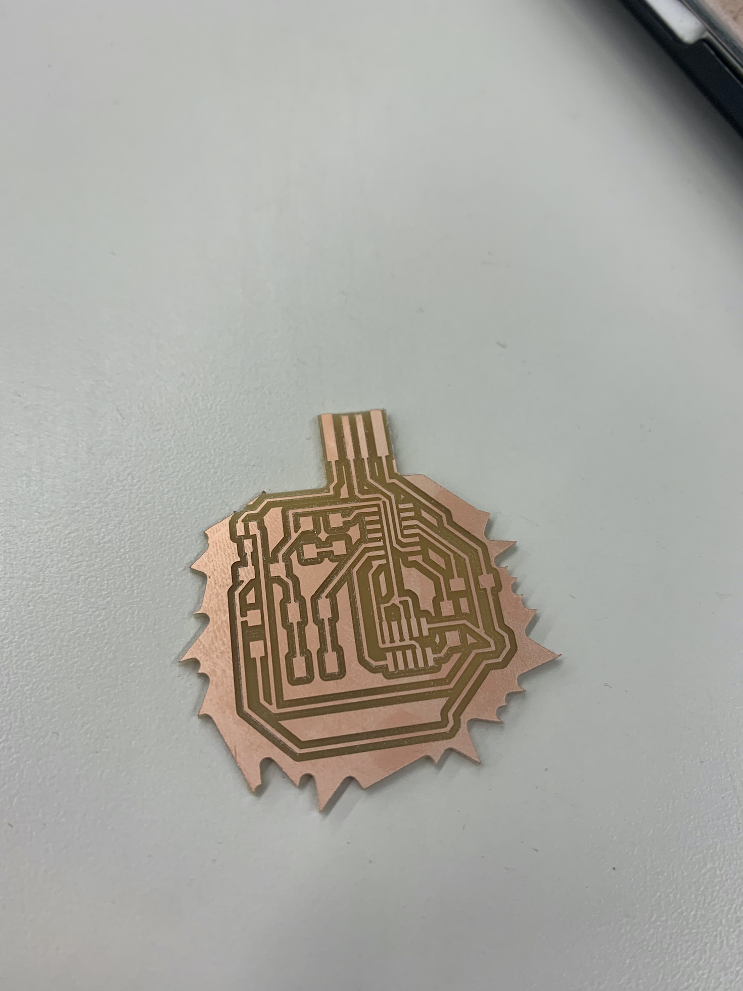
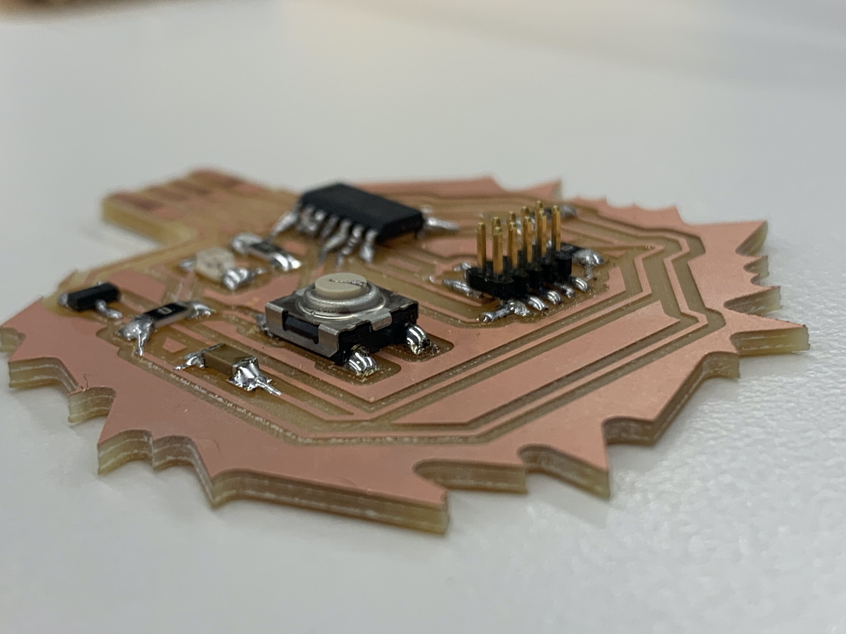
Finally. Success at last! A perfectly milled board. Or so I thought...
Soldering Struggles
Soldering was straightforward, but my skills were laughable as per usual.
Finally, after 20+ hours spent on this project...
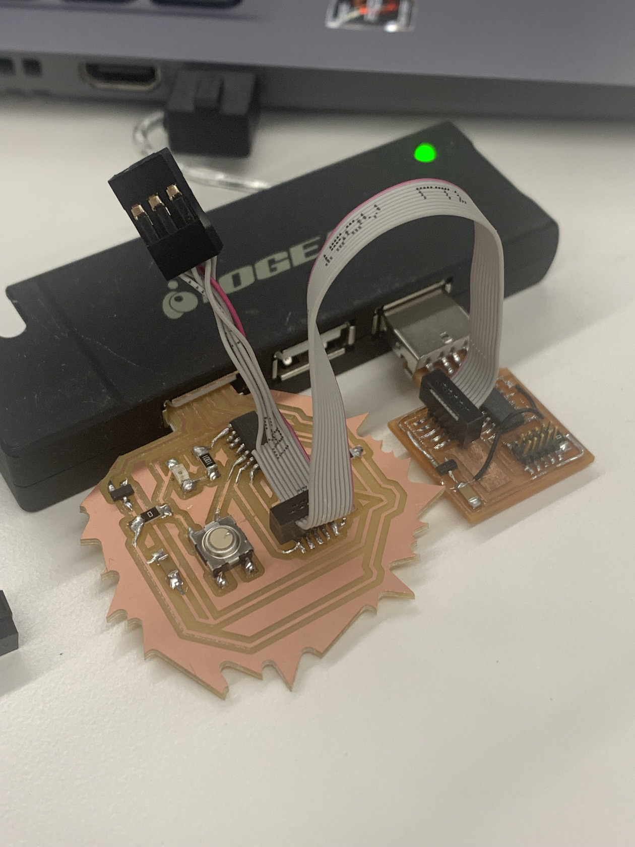
After soldering, I taped the back of the USB to prepare for testing.
Tumultuous Tests
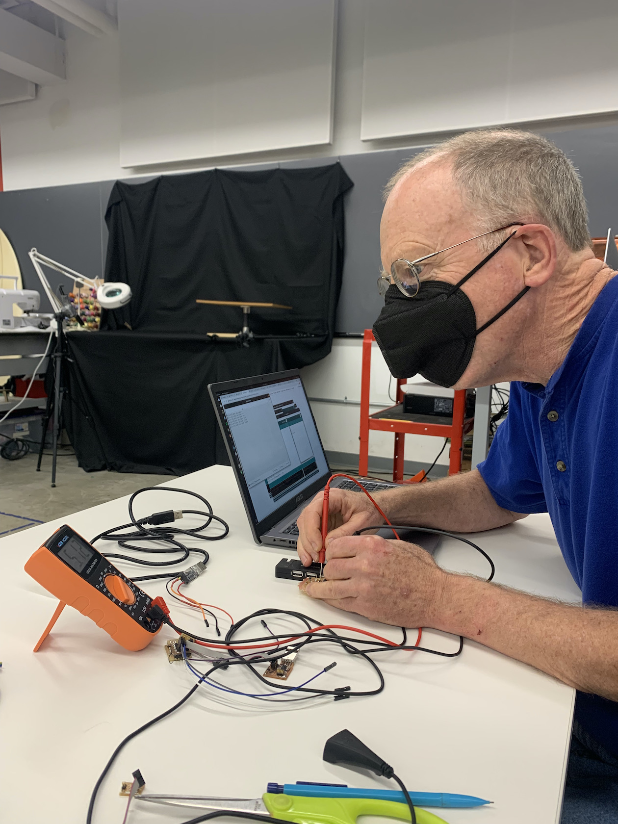
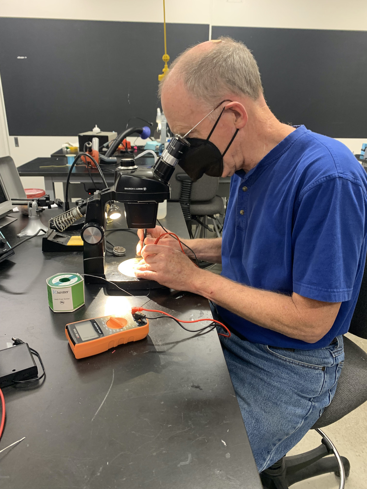
A hero emerges...
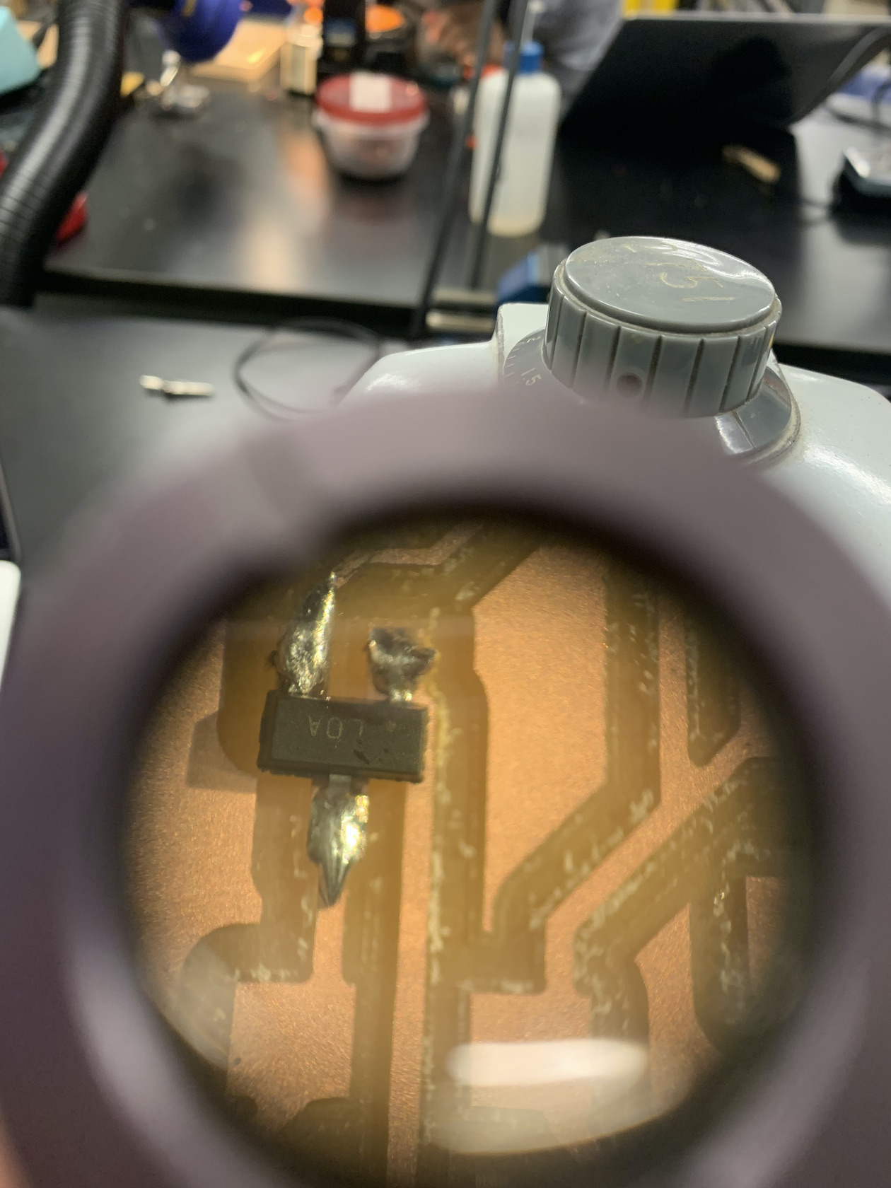
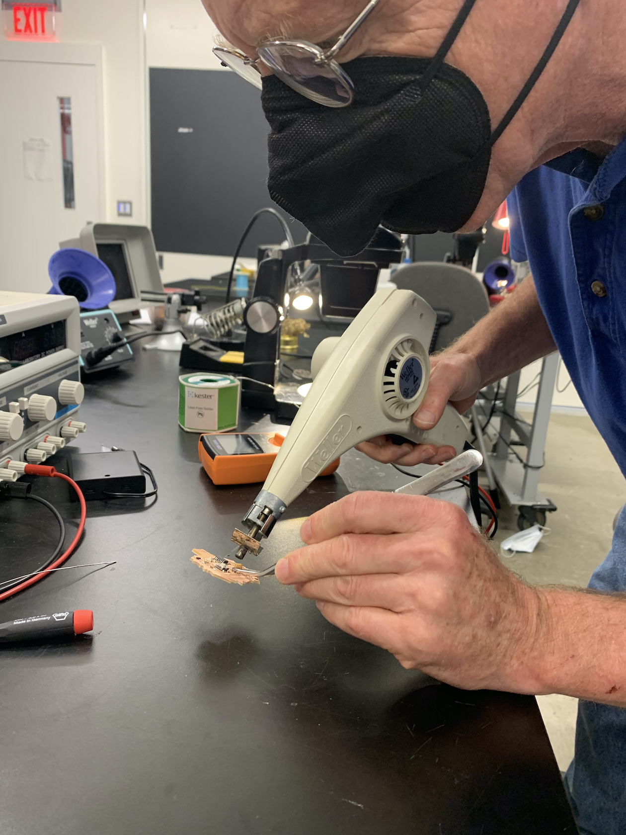
Rob really saved the day here. For a very long time, we could not figure out why my board was not working. He eventually discovered that one of my VDD lines was being grounded under my header. Using a heatgun (shown below), Rob found a spot under the connector where the mill had not completely separated the wire, something I fixed easily with a utility knife.
Emotional Ending
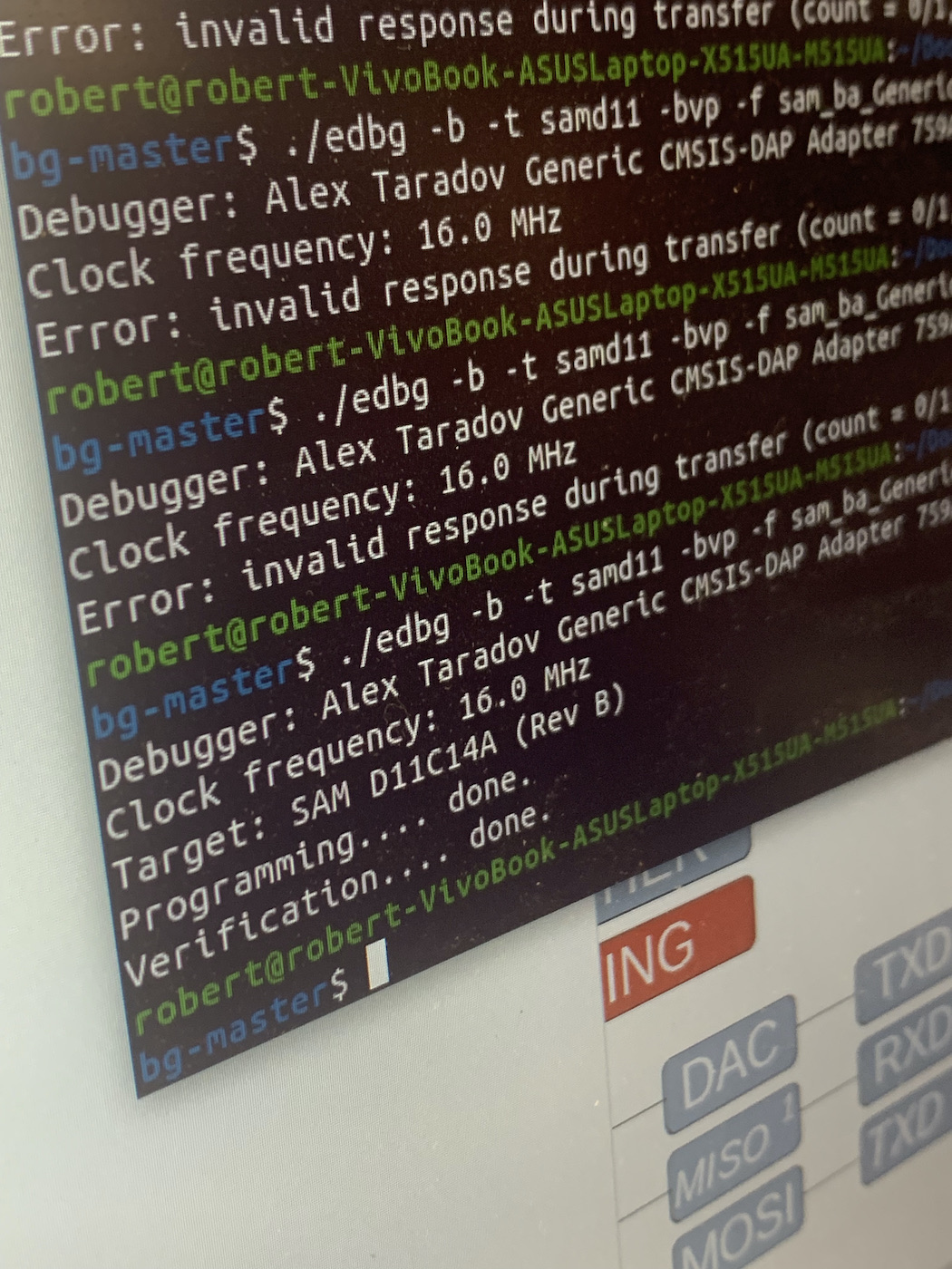
After soldering the header back on, the board finally worked. I'd like to say I am not lame enough to get emotional but let's be honest, this week was tough and it was such a relief. The LED was working according to the multimeter, but we could not see it because I accidentally used an IR LED. OH WELL