I love flying and I love airplanes. For a long time I wanted to be a pilot and perhaps a part of me still does. So it naturally made sense that in a class where one learns how to make (almost) anything, it should be quite possible to make an airplane. Of course, as it turns out, flying is hard. Although one could argue that my project doesn't really have that problem since my model is not quite flight ready technically. Perhaps one day I will build my very own flying plane, or even possibly will find a way to fly myself. But for the purposes of this final project, I choose to define the parameters of success not by whether or not my plane flies, but rather whether I build a plane-like object that has most basic motor controls of a standard RC airplane. In summary, I learned a lot from this work, both on the electronics side as well as the fabrication side. Although each section already had the experience of going end-to-end on building something complex in machine week, this project was a chance to do so individually. The rough steps of the project timeline are outlined below.
To begin, I had been thinking about simple plane designs from week 1, where I laser-cut a simple 2D kit of an airplane jet and put it together. Throughout most of the electronics weeks, I had also been working towards controlling both servo and BLDC motors. Most crucially perhaps, I came across this incredibly impressive DIY RC plane design (thank you Alfonso) with rather detailed step-by-step instructions in the corresponding YouTube video. This gave me a rough idea of how many servo motors I would need (4), as well as the rough idea for the actual 3D design which I cut out on the Zund during Wildcard week.
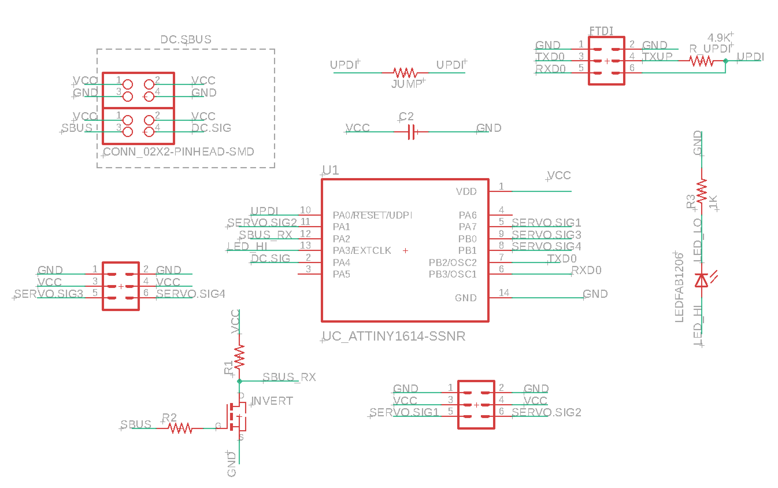
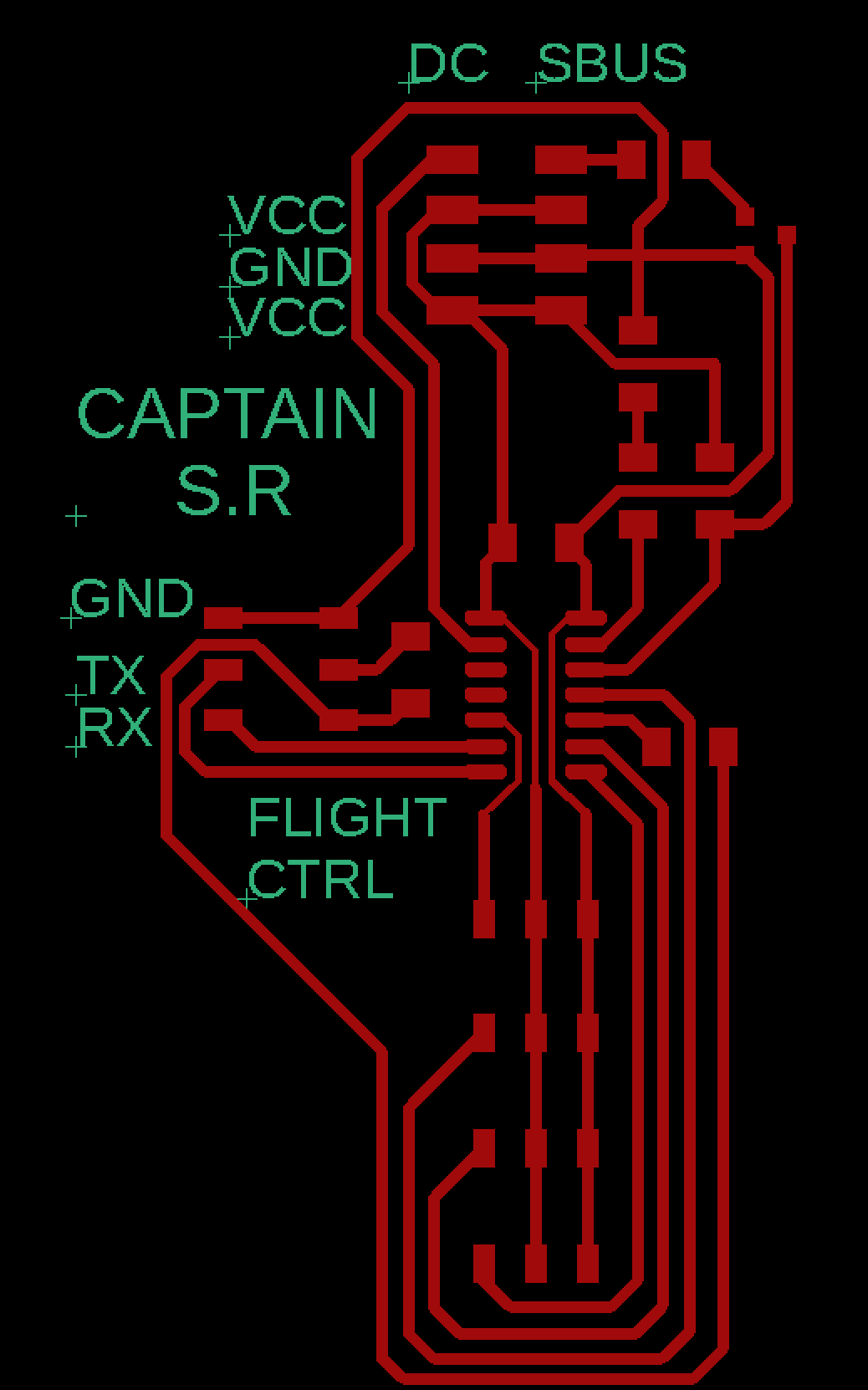
For the electronics, I essentially needed an ESC to control the brushless DC motor, as well as four pins for four different servo motors. The schematic and pcb designs are shown below:
I had already been working up toward this board, by milling some smaller boards to power servo
motors as well as a BLDC. In
output device week I made a board that could power
servo motors, though because I hadn't figured out the battery supply issue for the BLDC motor
I did not get that working for that week. However, the above designs ended up working with some minor
changes to how I had initially planned to use the board.
One unexpected issue which occured was that the default regulator on the ESC that I am using does
not supply enough current
to power all four servos simultaneously, so an alternatic strategy for supplying power was necessary.
Because I was already using an FTDI cable for GND, RX, and TX to program my board via UPDI as well as to
establish serial communication, I just connected a wire to the VCC pin as well. So now I am using the computer
to power the ATTiny 1624 microcontroller, and a 12V battery to power the BLDC.
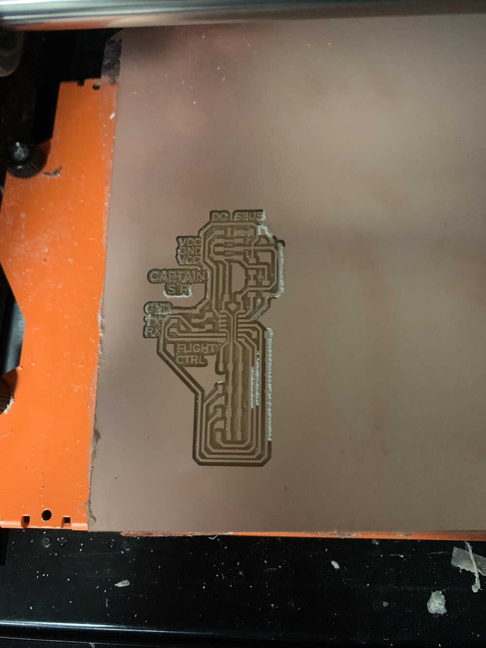
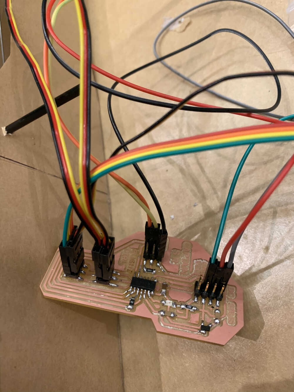
After milling and soldering the above designs I got the below:
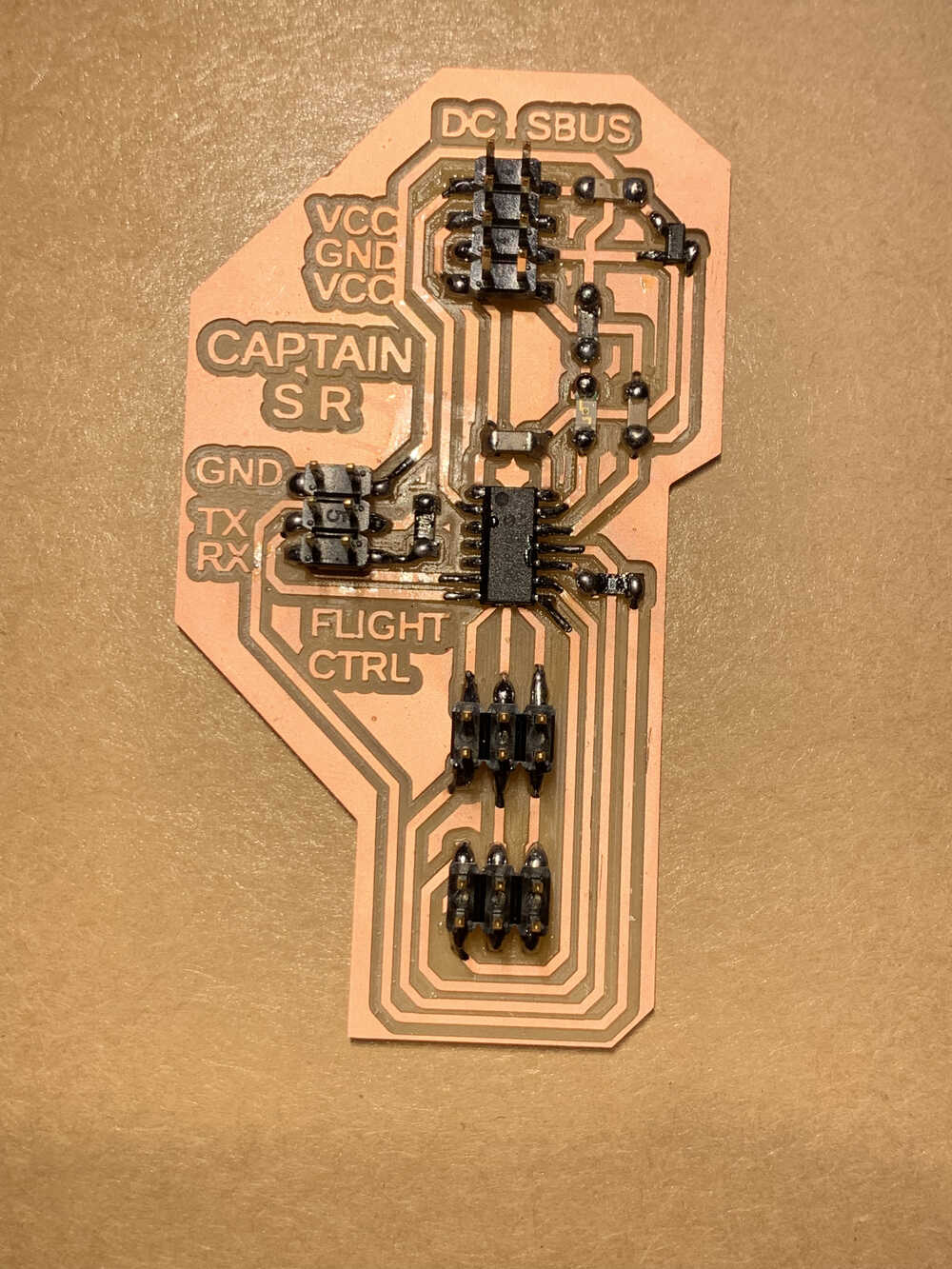
The basic idea of the above design is to have room for four servo motors to attach to the board
and for one ESC to attach as well (the DC column of pads). The decision to have two sets of VCC
pad pairs was a result of both a design mistake and redundancy. However, it does not mess up the
overall board fuctionality. In the end, that additional set of VCC pins only served to make
connecting wires a bit easier for certain occasions.
The SBUS column of pads connects to an external receiver. The initial goal of the project
involved operating the plane controls wirelessly via remote control. Unfortunately, that goal remained
unfulfilled by the end, though a lot of time was spent on establishing a connection between
the transmitter and the receiver. We used a
FrSky Taranis Plus
remote controller (manual
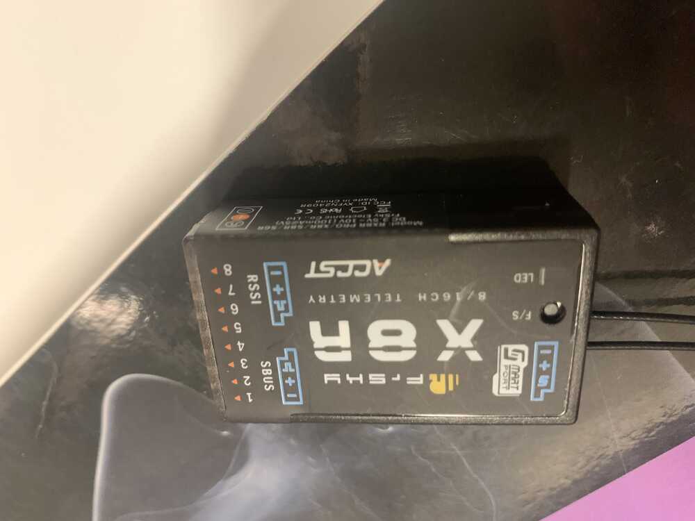
here) and an
FrSky X8R
receiver (manual
here), which looks like this:
To figure out pairing procedures I found
this video helpful.
However, after following the step-by-step directions laid out in the video, the receiver kept
blinking red (which means it did not connect to a transmitter). So after some digging around
I found that FrSky makes two versions of its firmare:
one that is EU compatible and one that is
"international". Based on this video
which details how to put compatible firmware onto the X8R receiver, and
this very helpful site, I decided
to load non-EU compatible firmware (the "international" one) onto my X8R and see if that
fixes the issue.
Though those two sources provide in-depth walkthroughs of how to do this, the basic idea is to
go here and install the right firmware, which will
download two files. One will be for EU firmware (LBT protocols) and one for US firmware
(FCC protocols). A helpful article in explaining this distinction lies
here.
However, despite going through all of that the pairing still did not work. After some more digging,
I found that the transmitter I had is very old and as such has old firmware installed on to it.
Furthermore, there is a separate firmware installed for the device's OS and for its radio systems.
After a lot more time spent on getting the firmware versions to match up across all channels (the
remote control's OS, it's radio firmware, and the X8R's firmware), and with a little bit of advice
from Nik, the pairing finally worked.
Here is a helpful article on
how to download different firmware on to a Taranis remote control.
Finally, after finishing this I looked into programming my microcontroller. Here is a helpful library for communicating via SBUS, and here is some guidance on how the hardware should be set up to handle the SBUS communication protocol (the signal needs to be inverted, which is why I have a transistor on the top right of my board). Sadly, at this point the battery on the Taranis died (as the remote control appears to be likely a decade old), and I was unable to source another battery supply and/or charge the battery in time for the final project to be completed.
Having accepted that I would have to signal my controls via RX and TX communication on via computer, I went ahead with that plan. First, to do an initial test that the board works, I made three servos move repeatedly for their full 180 degree range:
The relevant code to achieve the above functionality looks something like this:
        for (pos = 0; pos <= 180; pos += 1) {  // goes from 0 degrees to 180 degrees

            // in steps of 1 degree
            myservo.write(pos);  // tell servo to go to position in variable 'pos'
            delay(15);  // waits 15ms for the servo to reach the position
          }

          for (pos = 180; pos >= 0; pos -= 1) {  // goes from 180 degrees to 0 degrees
            myservo.write(pos);  // tell servo to go to position in variable 'pos'
            delay(15);  // waits 15ms for the servo to reach the position
          }
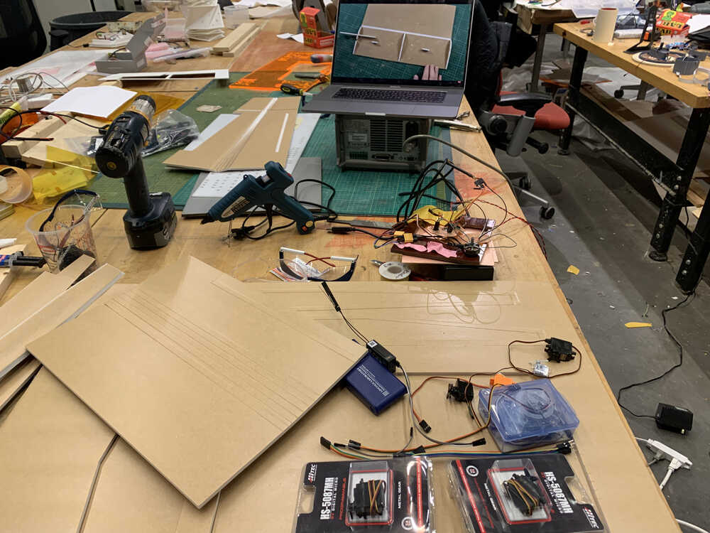
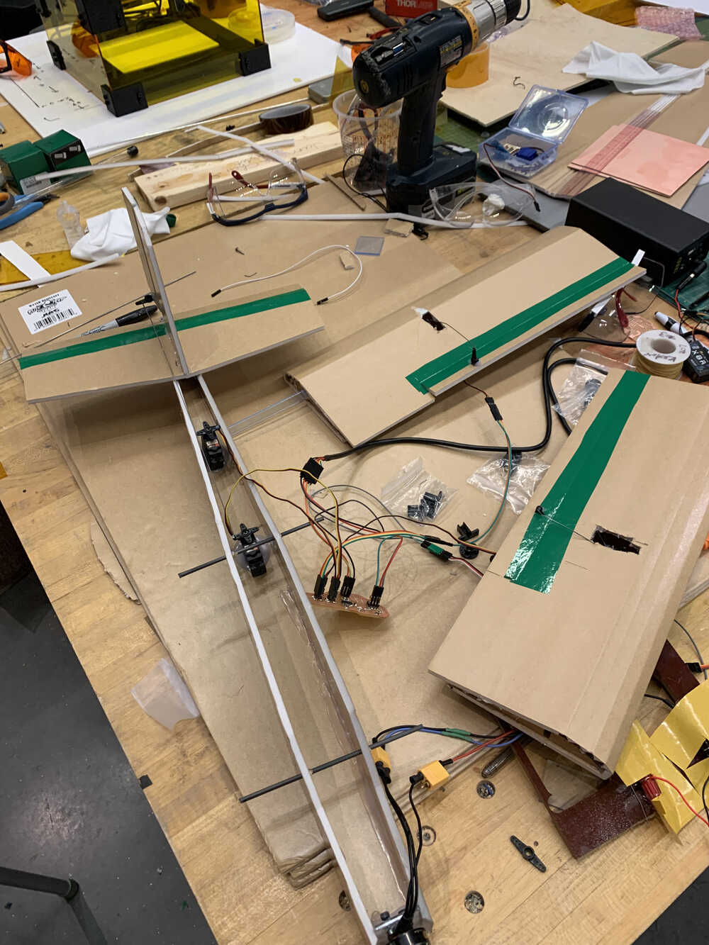
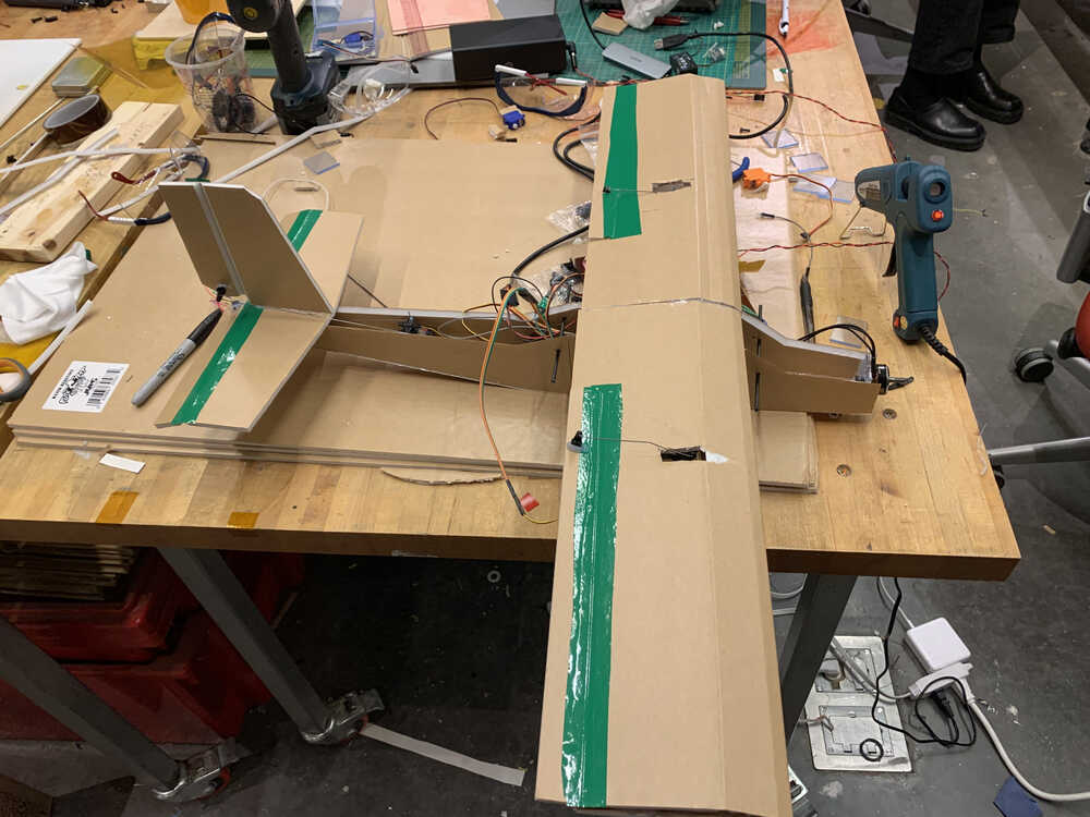
After getting basic funtionality from the controls, it was time to put everything together. Using the cutout made during Wildcard week, I finally moved into the shop and began gluing things together. Here is how everything started:
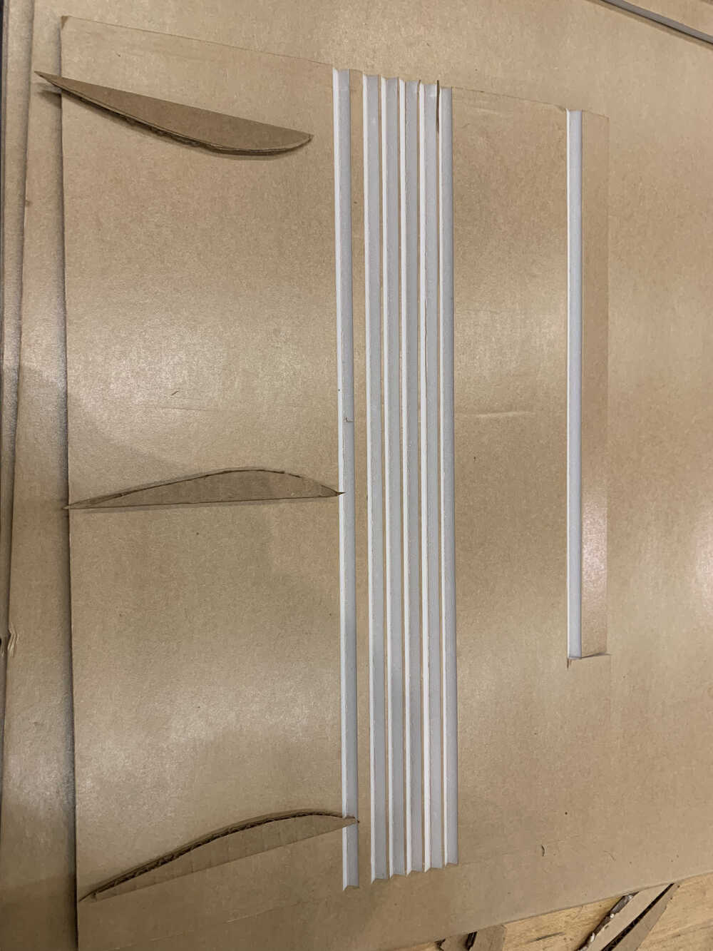
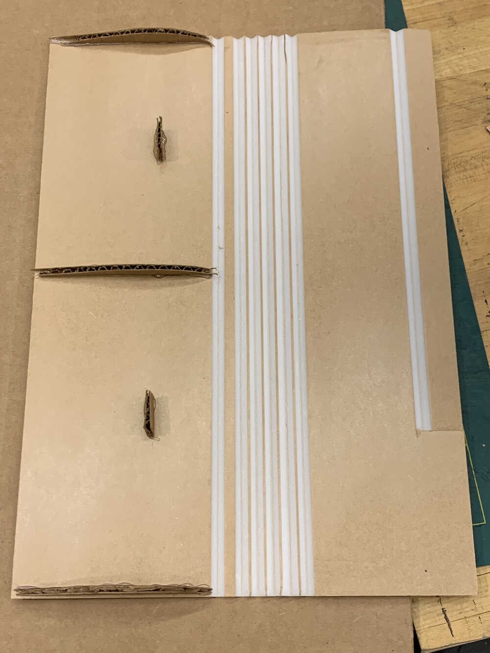
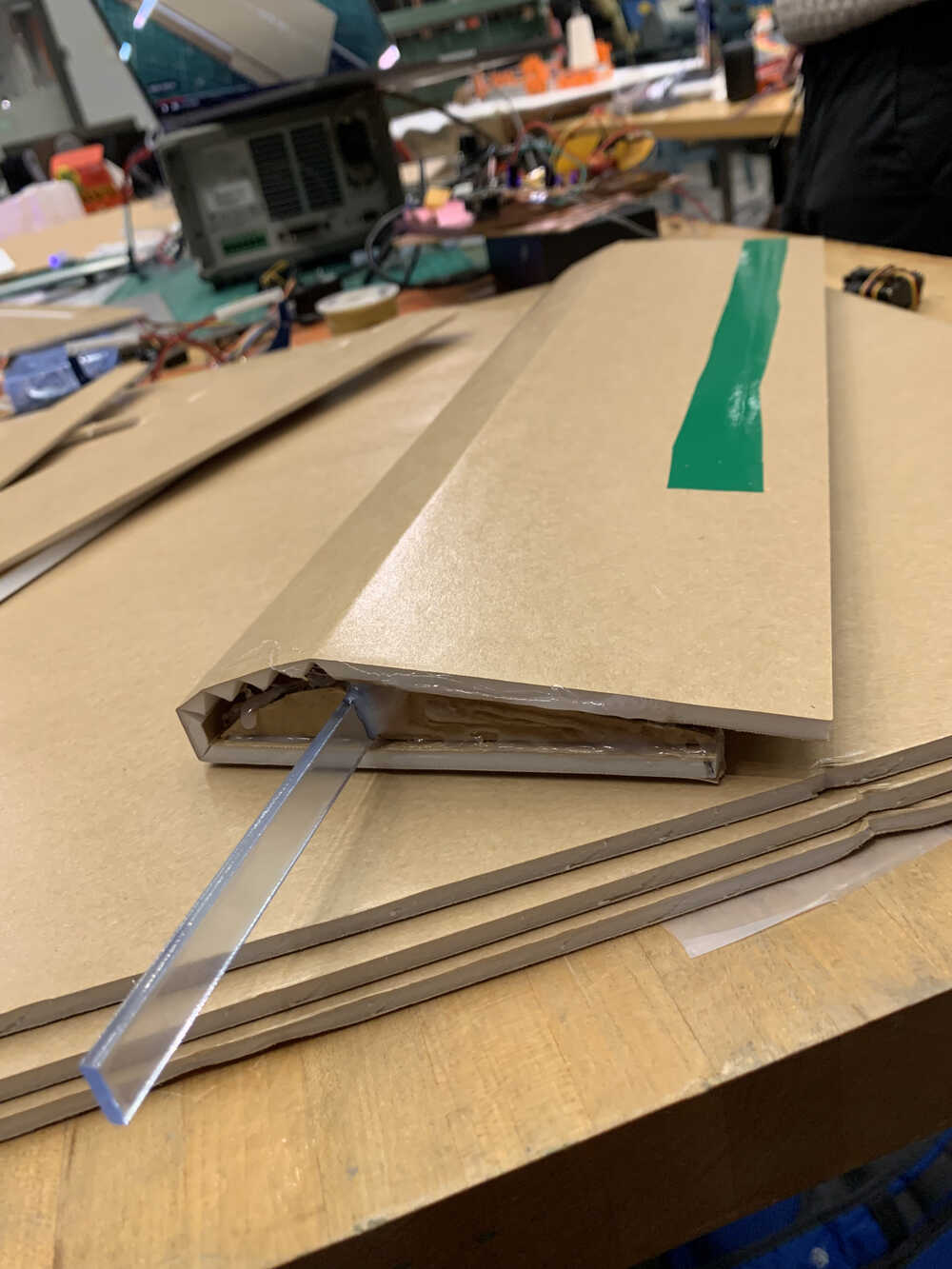
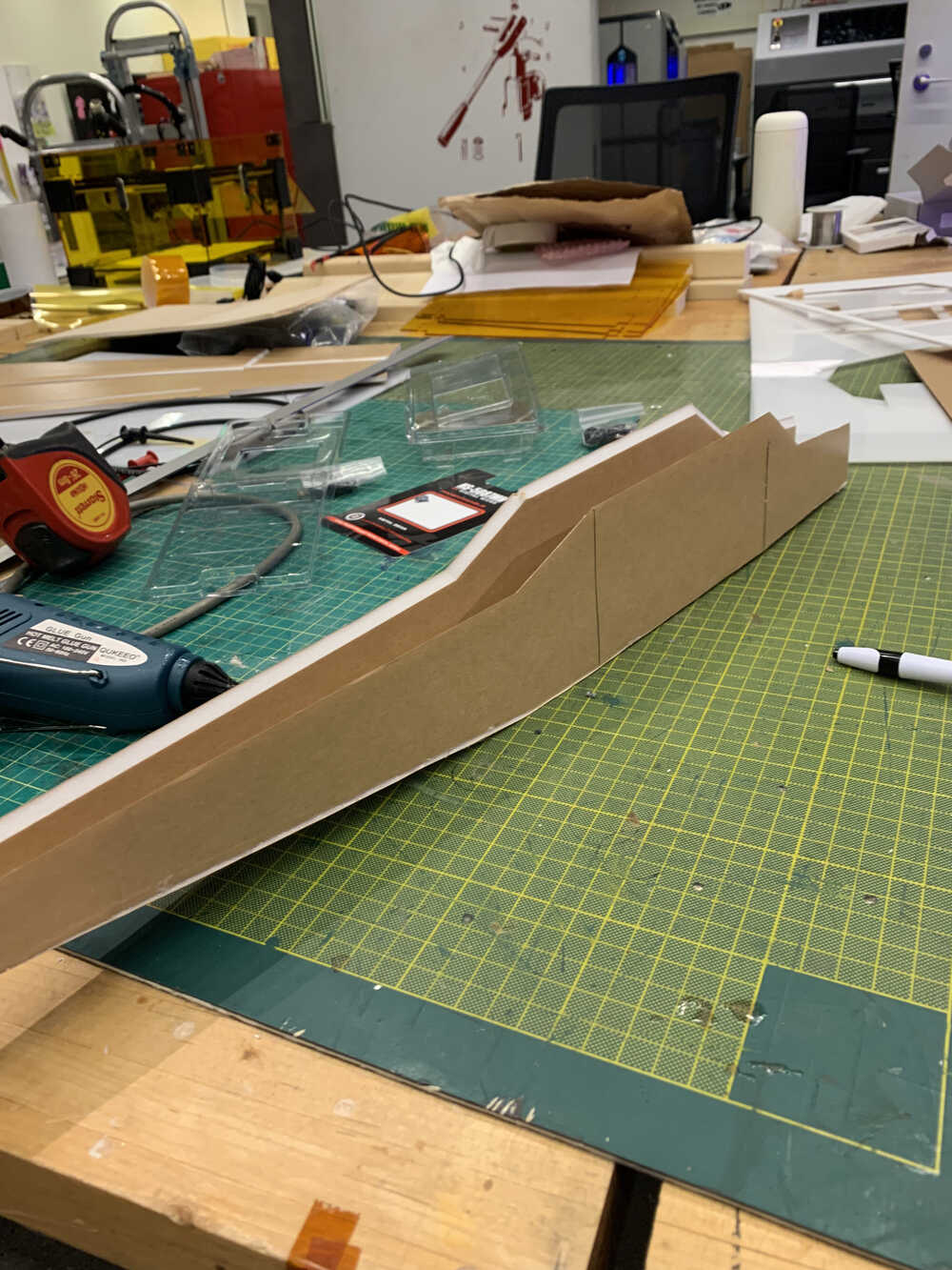
The first step was to make the wing, which involved cutting some supports that would shape the wing. Below we can see those supports cut out by hand, as well as how the wing looked when folded. Note that I added an additional support (in the form of a small acrylic prism) to hold the two wings together in the end. Here is how all of that looked like:
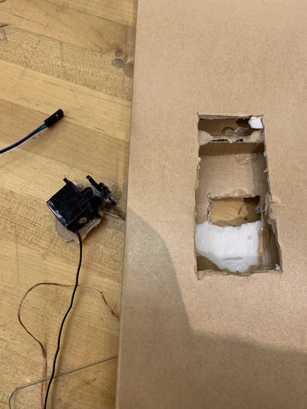
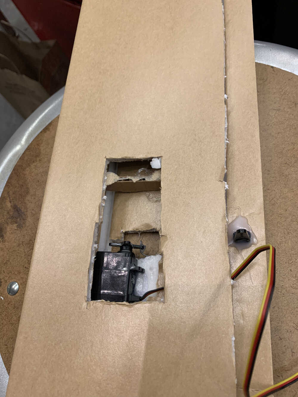
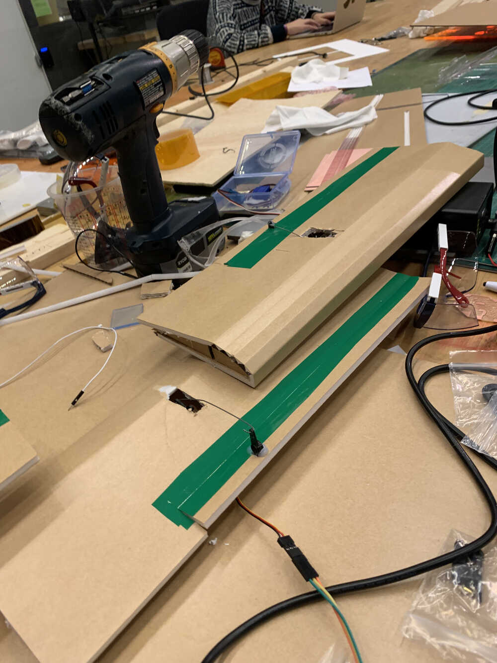
After finishing this, it was now time to hook up a servo motor to each wing and to find a place to house it. As it became obvious that this model was not going to fly by the demo, as I did not have a working method for controlling the motors remotely and did not have a LiPO battery to power the whole plane, I was a bit more generous with some of the cuts I made to house each servo as aerodynmics were no longer a major concern. Below we can see a rather large cutout that was made for one of the servos (a similar one was made on the other wing as well):
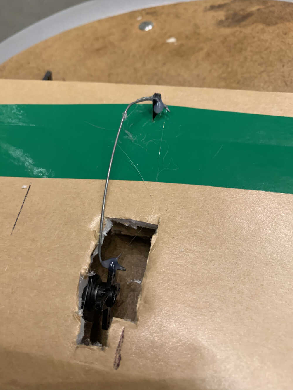
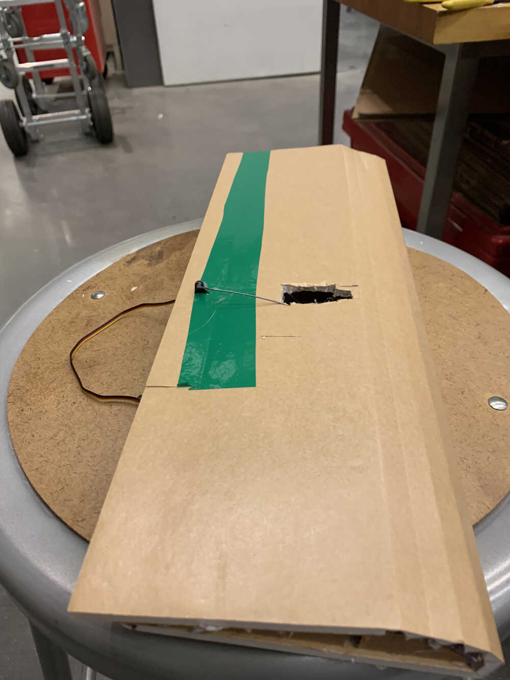
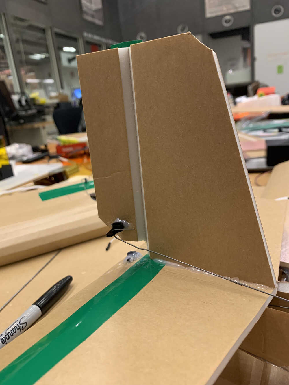
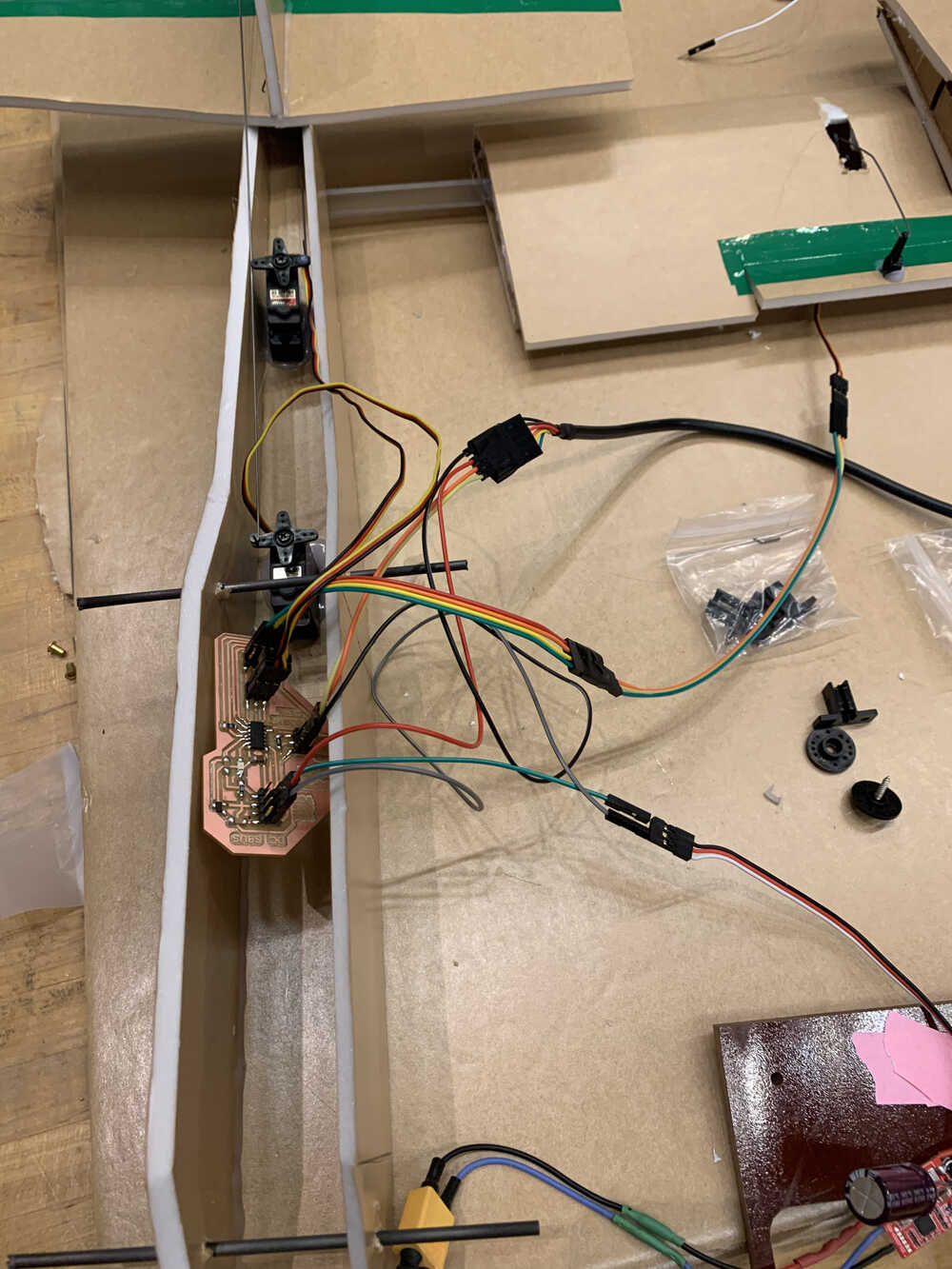
Now it was time to connect a wire between the servos and the aileron in order to make it move. To do that I found some thin wire, and rather painfully hooked it up to the aileron and servo. The big challenge here was that the motor has a neutral position from which it can turn an equal amount in either direction. However, it was hard to make the wire be exactly the right size in order to connect the aileron to this exact position of the servo. This is why the movement up and down of the ailerons (and indeed the elevator as well) is not an equal amount up and down. Here is what the wiring looked like:
Having a fully hooked up wing meant one thing: it was time to test for movement. I connected the servo to the board and sent a very simple signal to make the servo move. We can see the first signs of life below:
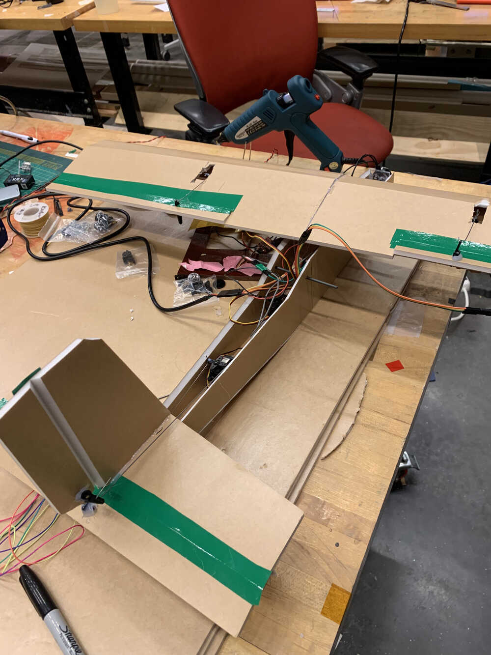
Now it was time for the frame to be put together, that was not too difficult to glue together. I also glued the elevator and rudder together though, and again had to hook up some wiring between them and a pair of servos to be housed inside the body of the plane. Here is how that looked like:
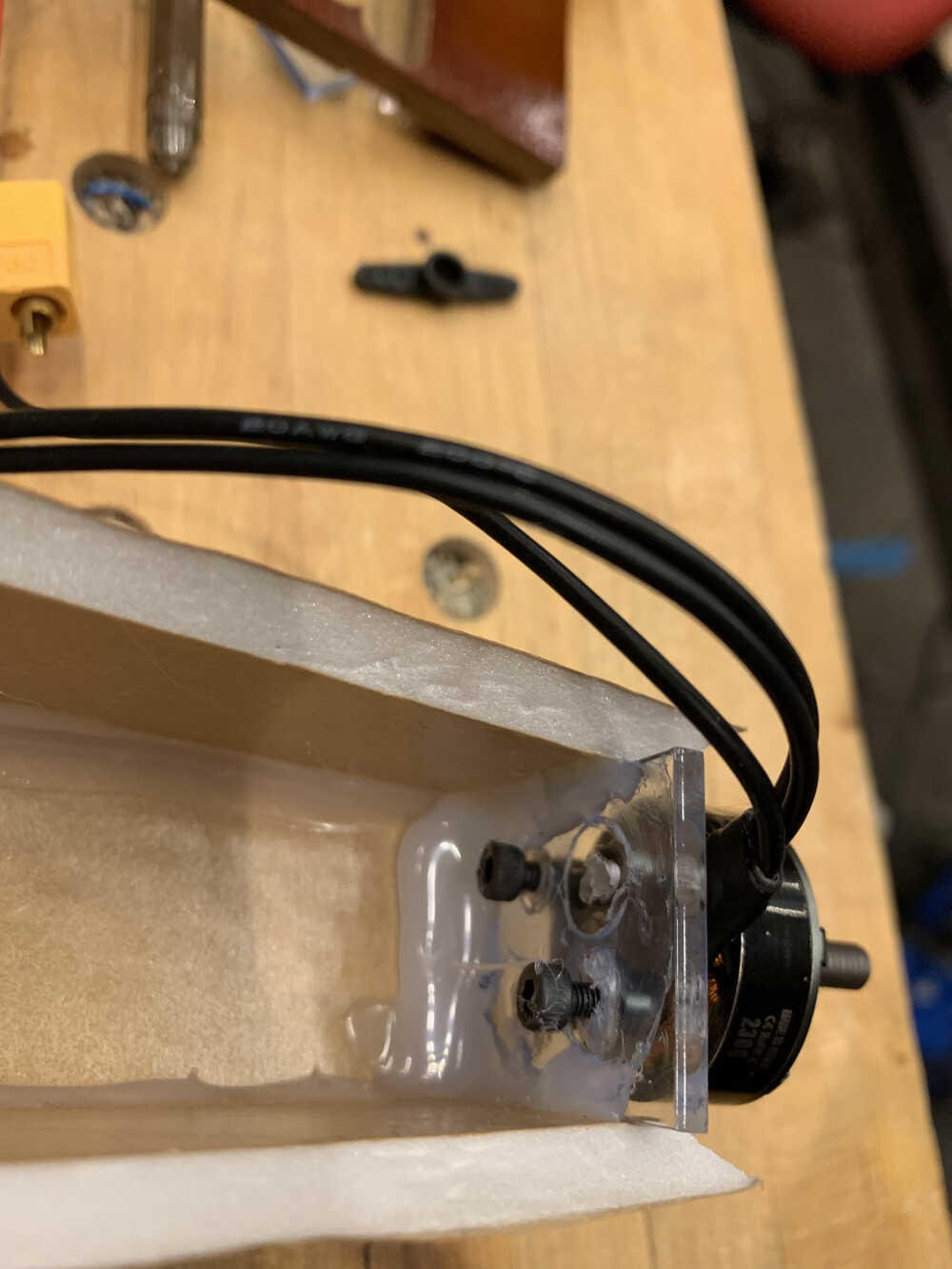
I also hooked up the BLDC to the front of the plane. For that I cut up a small rectangular prism on the laser cutter and drilled some holes through it for the BLDC. With some hot glue on the sides, the acrylic support was relatively stable once inside the frame. Here are some photos of that:
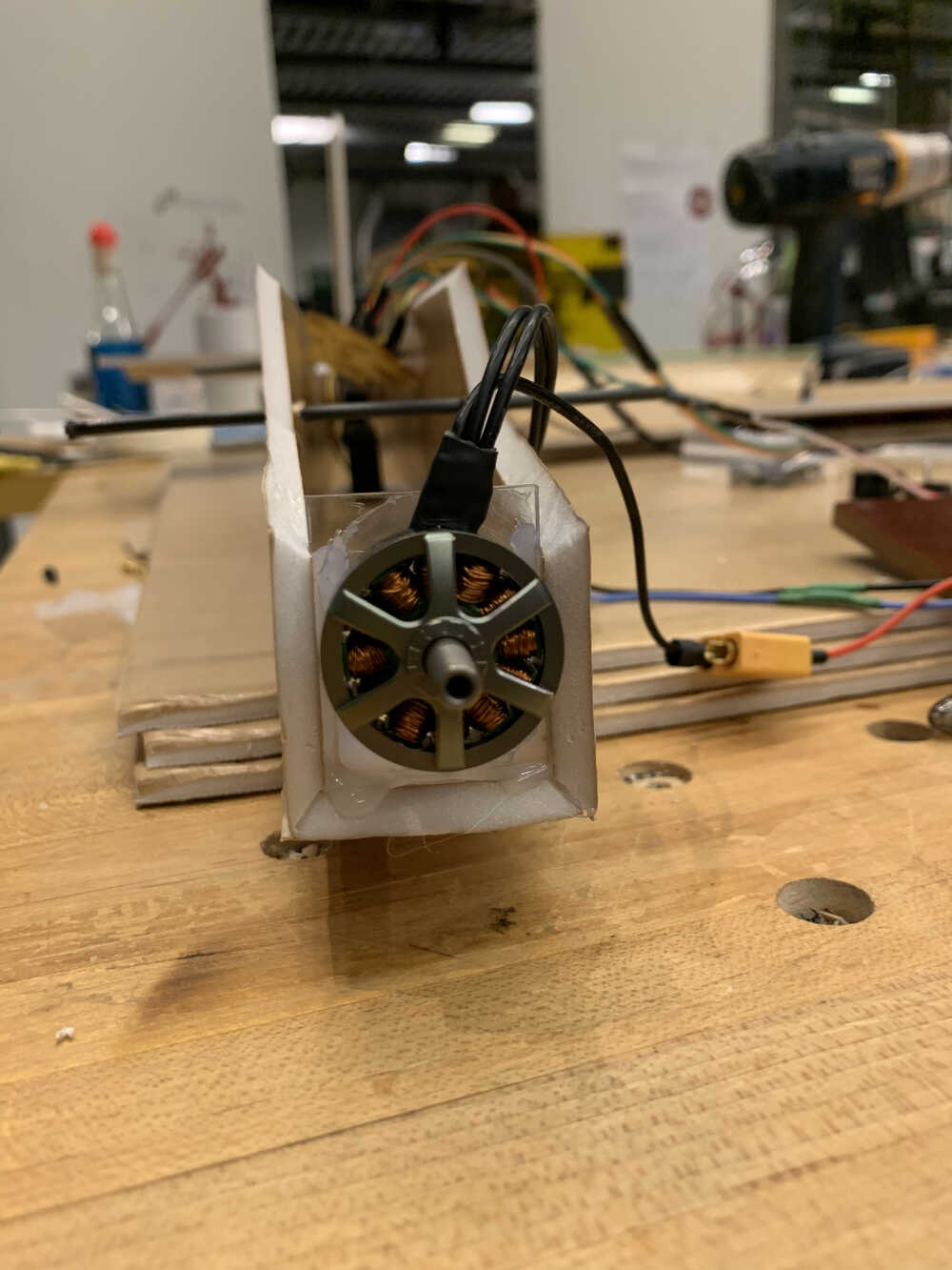
And finally, I tested the movement for both the elevator and rudder as well as the BLDC up front:
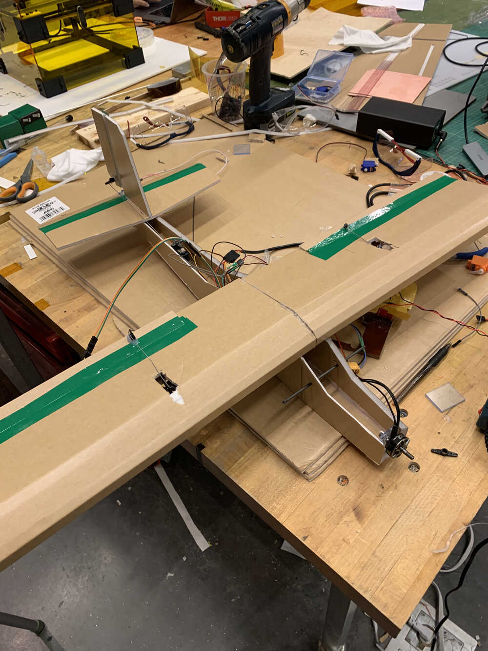
As everything was working on its own, it was now time to put it together. As there is quite a bit of wiring on the board, it was a little tricky getting everything to fit inside the frame. Though I was able to make it fit when slightly tilted:
Glueing the wings together and putting them on top of the plane finally gave my creation some resemblance to a plane-like object:
To stabilize the wings, I wrapped some rubber string around the wings and two small rods
I put through the body of the plane. This was largely to make the wing top removeable to more
easily swap out some electronics, or re-program the board if necessary. Additionally, I decided
against covering up the open parts on the top of the plane for the same reason. Theoretically, a
more finished version would include a lipo battery, an additional small regulator board (or
perhaps a new board altogether), and the X8R receiver, all inside the body of the plane. It would
be a lot easier to make those changes while having all that space open. And lastly, I thought it best
that since this was not a completely finalized product, it would be better to show some of the inner
workings for the demo. Of course, I learned at-presentation that that did not count for packaging
and that a less wire-visible final version is much preferred, so
mea culpa.
Nonetheless we can see a full demo of all of the controls working below, via the interface
built for Interface + Application week.
Making a plane fly turns out to indeed be an ambitious project, even for a class like this one. Certainly with a bit more time I could have gotten to a better place towards that goal, but this was a rather taxing semester and I did indeed spend a lot of time on this project regardless. I started out the semester having never even heard of the word solder, and with no prior study of electronics, so for me even getting this far is a success. Of course, I had a lot of help from many people across the board, and any attempt at making a complete list of everyone who helped me would be quite futile, but there are a few specific thank yous that deserve to be mentioned. Firstly, I a very greatful for Miana's teaching and support all throughout the semester. What little bit I know of how to make PCB boards and design circuits I got mainly from her, not to mention the countless hours that she spent teaching me the basics of electronics. I also got massive support from Nikhil, who gave me great guidance on how to structure my physical and electonic fabrication and a plan for dealing with hardware issues (indeed this plan works for other problems too, but was mainly used on the hardware problems - ask him for details but step 1 is panic). Many thank yous to Alfonso as well, for plane design and Zund cutting, Dave for BLDC arming and control, Quentin for electronics, and many others I'm sure who I have inevitable missed. This was a fun semester (mostly) and I learned a ton, so I consider it largely a success.