Week 11
Networking & Communication
Charlieplexing with sewable circuits and LEDs
If you hadn't figured out from my About me page, I love sewing. For this week's assignment, I decided to make a sewable PCB complete with sewable LEDs that I can attach onto fabrics using conductive thread. I would use the ESP32 to get multiple the LEDs to light up, and I would use charlieplexing to connect at least 6 LEDs together. With this inspiration in mind, I got to work.
svg-pcb
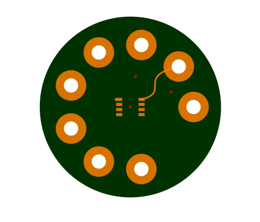
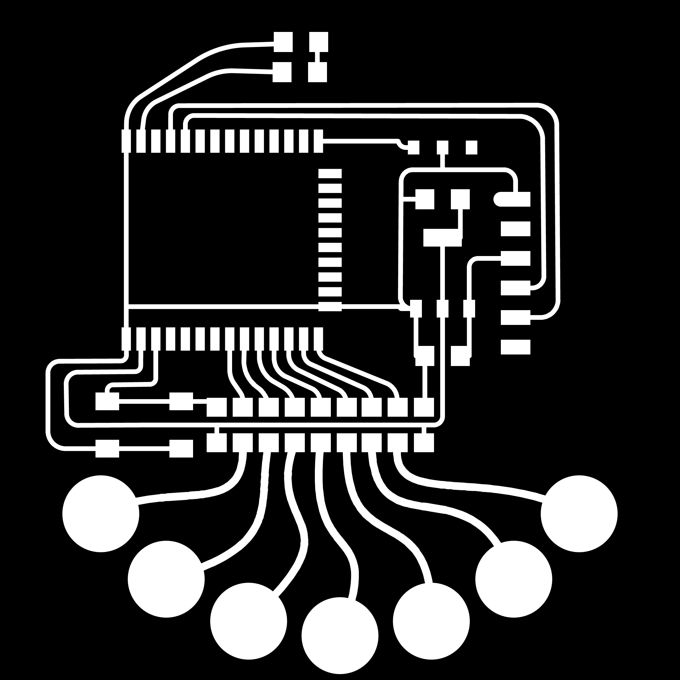
Designing the board in svg-pcb was really fun. I had help from Quentin to design the holes. The holes are necessary for sewing, and need to have enough copper plating for the conductive thread to make a secure connection:
/* -- DECLARE_COMPONENTS -- */
const footprint_holes = {};
const n = 9
const i_ignore = [n-1,];
const r_holes = 0.62;

// create a custom footprint
for (var i=0; i < n; i++) {
  if (i_ignore.includes(i)) {
    continue;
  }
  let hole = geo.circle(0.07);
  let hole_plating = geo.circle(0.15);
  let hole_pos = [r_holes * Math.cos(i * 2 *Math.PI/n), r_holes * Math.sin(i * 2 *Math.PI/n)];

  footprint_holes[i.toString()] = {
    "shape": geo.getPathData(hole_plating),
    "pos": hole_pos,
    "layers": ["F.Cu"]
  }

  footprint_holes[i.toString()+"_hole"] = {
    "shape": geo.getPathData(hole),
    "pos": hole_pos,
    "layers": ["drill"]
  }
}
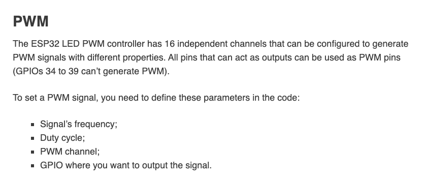
I used Neil's template on the ESP32-WROOM board and this page to decide which pins I wanted to use. I need PWM pins, and the good news is that I can use any output pin for that:
I was dangerously close to wiring the paths I needed from underneath the ESP32 emerging from under the antenna. My gut feeling wasn't on board with that, and after a quick google search I found the website from a previous HTMAA student (Cat Fang) who warned against doing that.
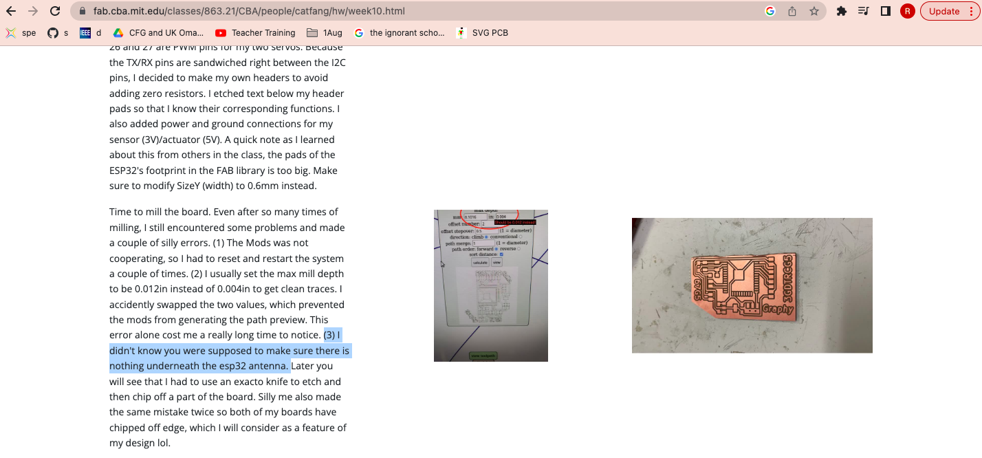
Thank you Cat.
With that in mind, I jumped the 3V3 path instead using 0ohm resistors. In hindsight, and from Jake's (TA) advice, I could have made a vias for that path and had a wire come out at the back of the board for the 3V3 route. I will do that next time!
I used fillets for each corner of the traces, which is easy to do. Here is an example:
//IO12 to hole 18
board.wire(path(IC2.pad("IO12"),
	["fillet", 0.02, pt(-0.043, -0.372)],
	["fillet", 0.02, pt(0.228, -0.49)],
	R20.pad("2"),
				), w);
Board V1 - Too many resistors
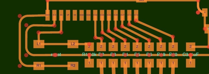
I initially set out to have as many sewable pads as possible, which meant using as many pins on the ESP32 as I could. That lead to quite a big board (10cm) with so many resistors I would get kicked out of HTMAA. So 5 minutes after I decided I was done designing the board, I started over again. Here is the old board: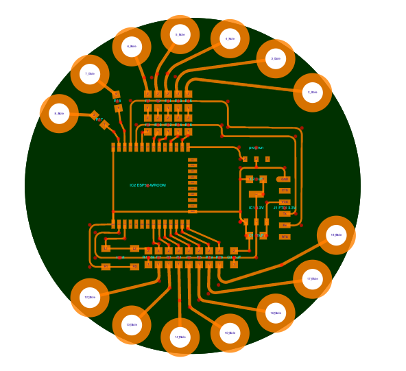
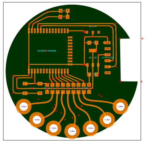
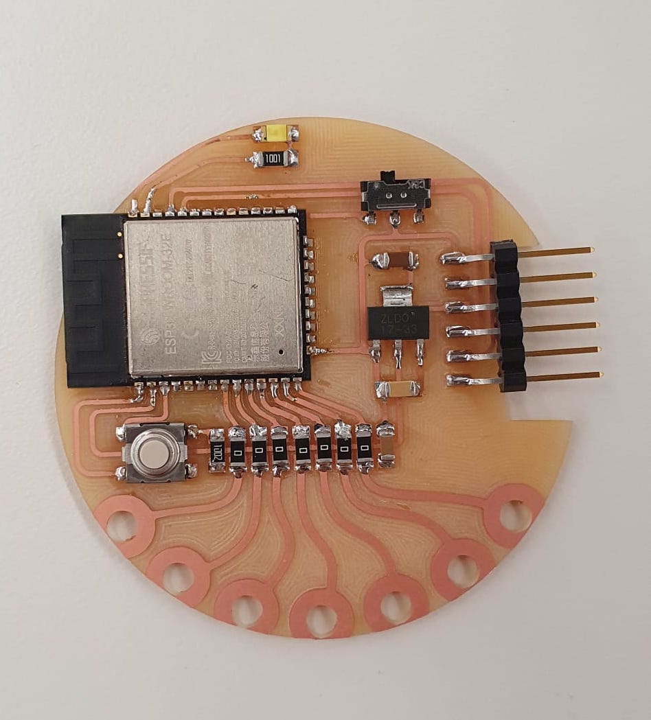
I ended up only using the pins on the left side of the ESP32 (pins IO32 to IO12), and using the two free pins (IO23 and IO22) for an onboard LED. They always come in handy.
I also had a lot of fun playing around with the bezier lines. I ended up using Beziers to create a trace from the resistors to the sewable pads. A few things to keep in mind when working with the ESP32:
- As Cat said, you can't have traces coming underneath the antenna, it would mess up the signal.
- For the FTDI header, you need to cut a square as big as the female FTDI that will eventually connect to your header.
Code file can be found here
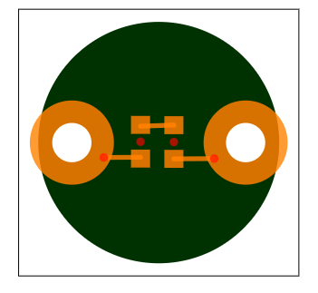
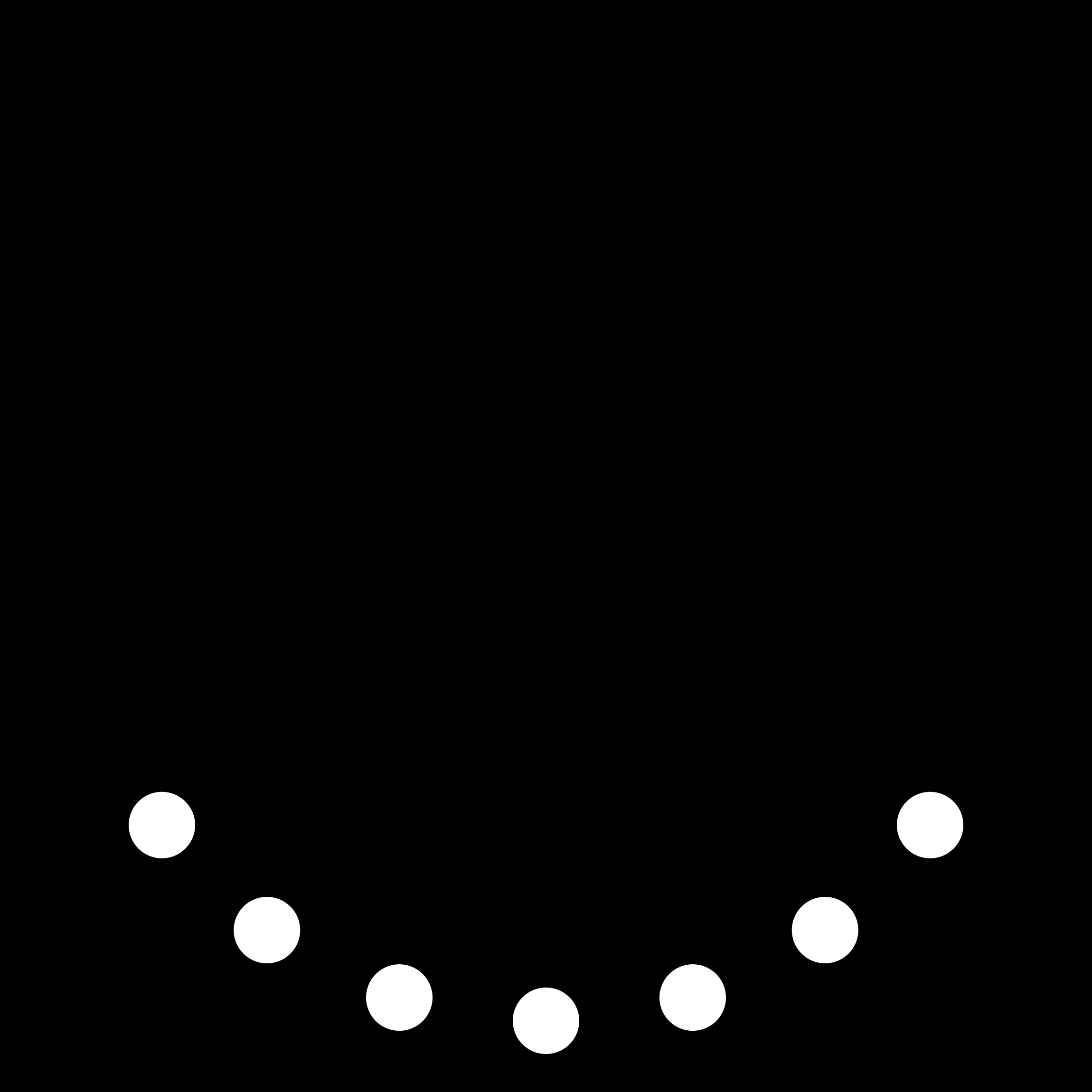
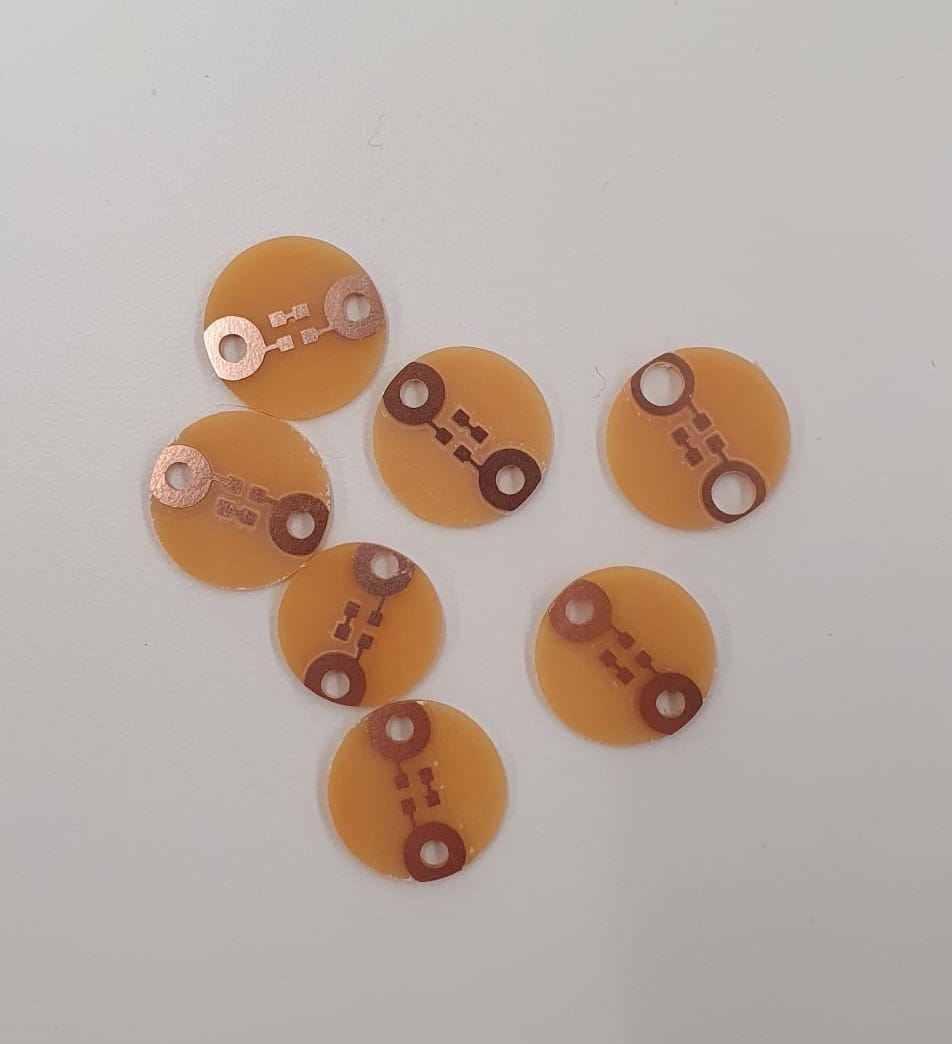
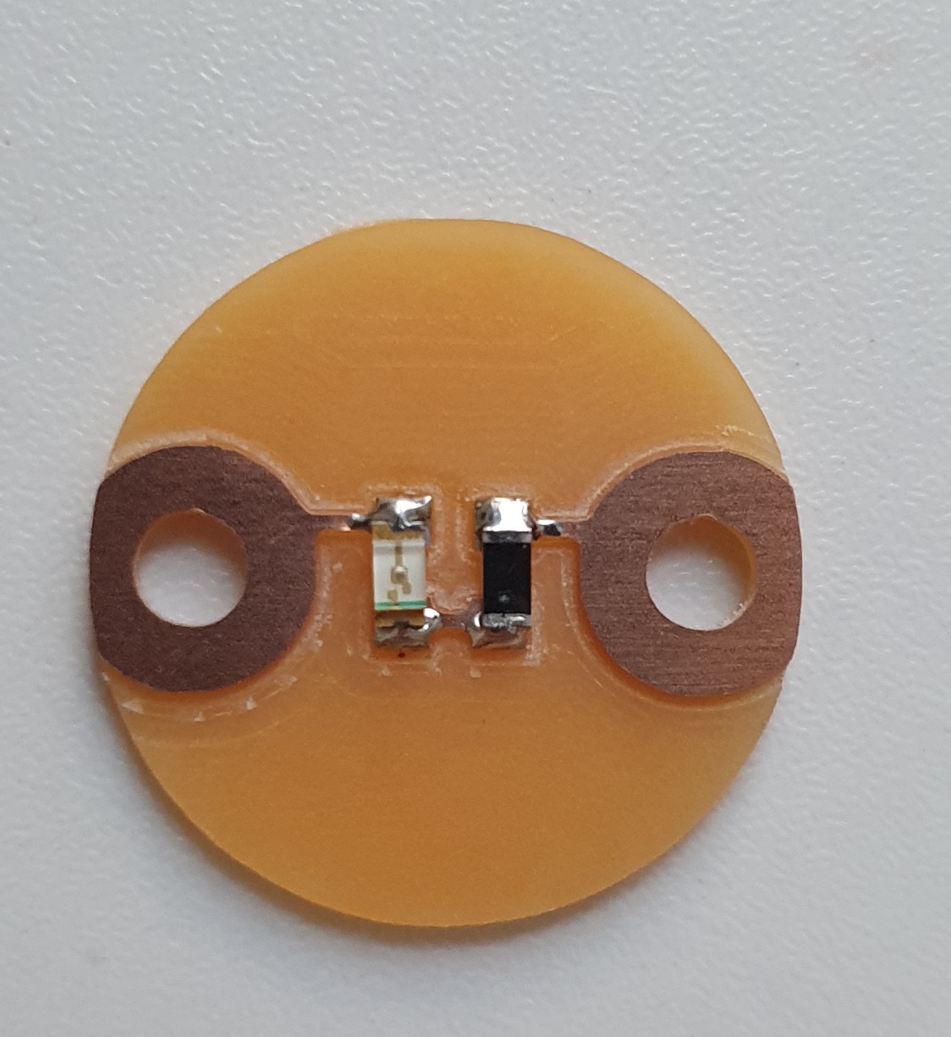
I also made sewable LEDs using the same hole-code from before:
Milling
I used three files to mill my board:The traces (I used the same file for copper clearing too)
The holes
And the outline

For the LEDs, I had three files too:
The traces (same file for copper clearing)
.png)
The holes

And the outline

The copper clearing technique is the best!
And this is how the LEDs came out:
Soldering
The soldering was pretty easy. I did discover I don't like lead-free solder. It's not shiny at all.
Here is my board:
And here is the LED:
Bootloading
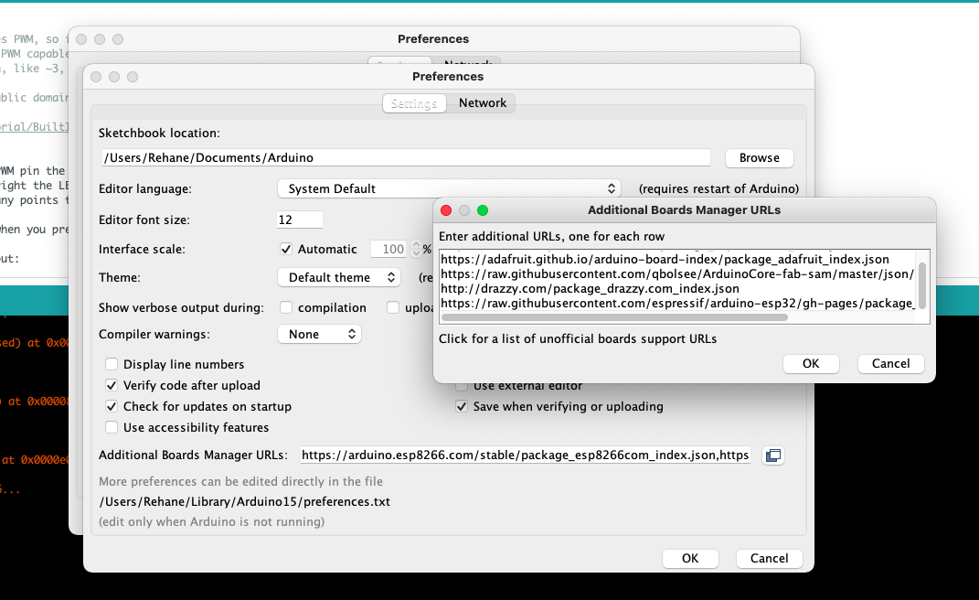
Quentin programmed my board and I have no idea how he did it, but I am determined to figure out the steps so stay tuned here.I did install the Espressif Arduino library from this link. You need to copy this line:
https://raw.githubusercontent.com/espressif/arduino-esp32/gh-pages/package_esp32_index.json
and paste it in the Additional Boards Manager:
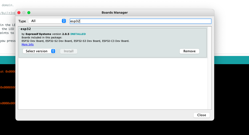
You also need to install the ESP32 library under Boards Manager:
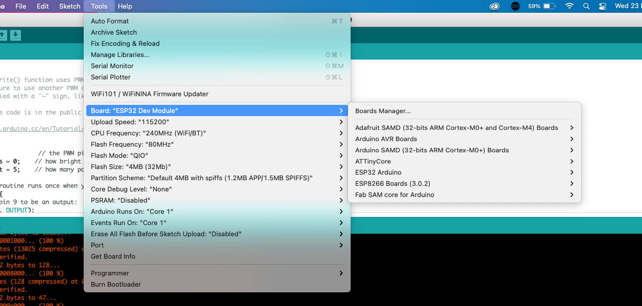
Select the right board under Tools:
Programming
Now for the actual programming, I ran into a few problems. First the USB cable connecting the programmer to my laptop was playing funny, but I thought it was a problem with my Arduino settings so I spent a lot of time trying to debug that.After that was solved, I kept on getting errors when I tried to upload a sketch:
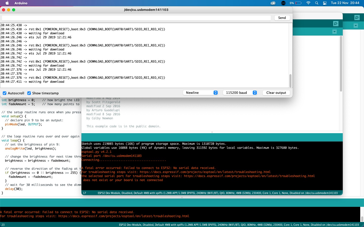
I was very very lucky to have Leo around around and he quickly realised that the switch needs to be connected to IO0 to be in noral execution mode, otherwise it's in bootloader mode and connected to GND. Here is the page outlining this in more detail.
Specifically, this is where you want to look at:
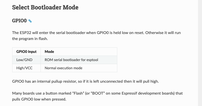
That means that the switch needs to be switched to the outer left to be able to be programmed from Arduino:
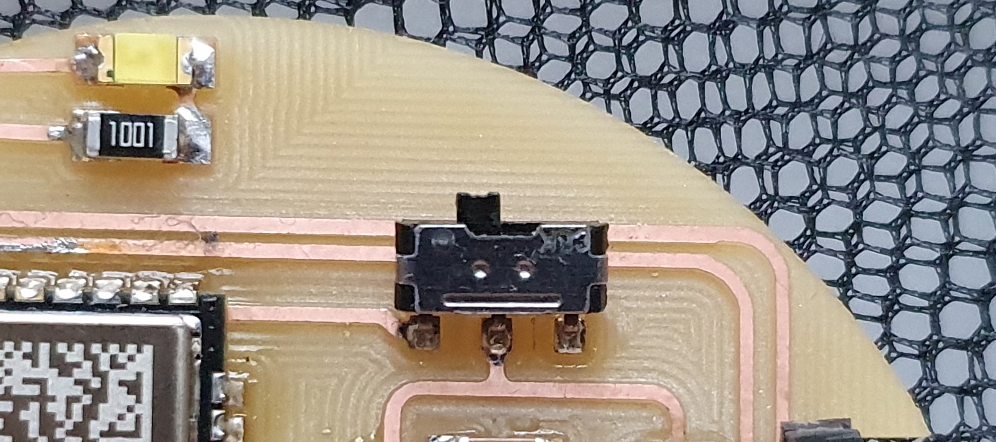
Every time you want to upload a new sketch, unplug your board from the programmer. Props to Leo for this!
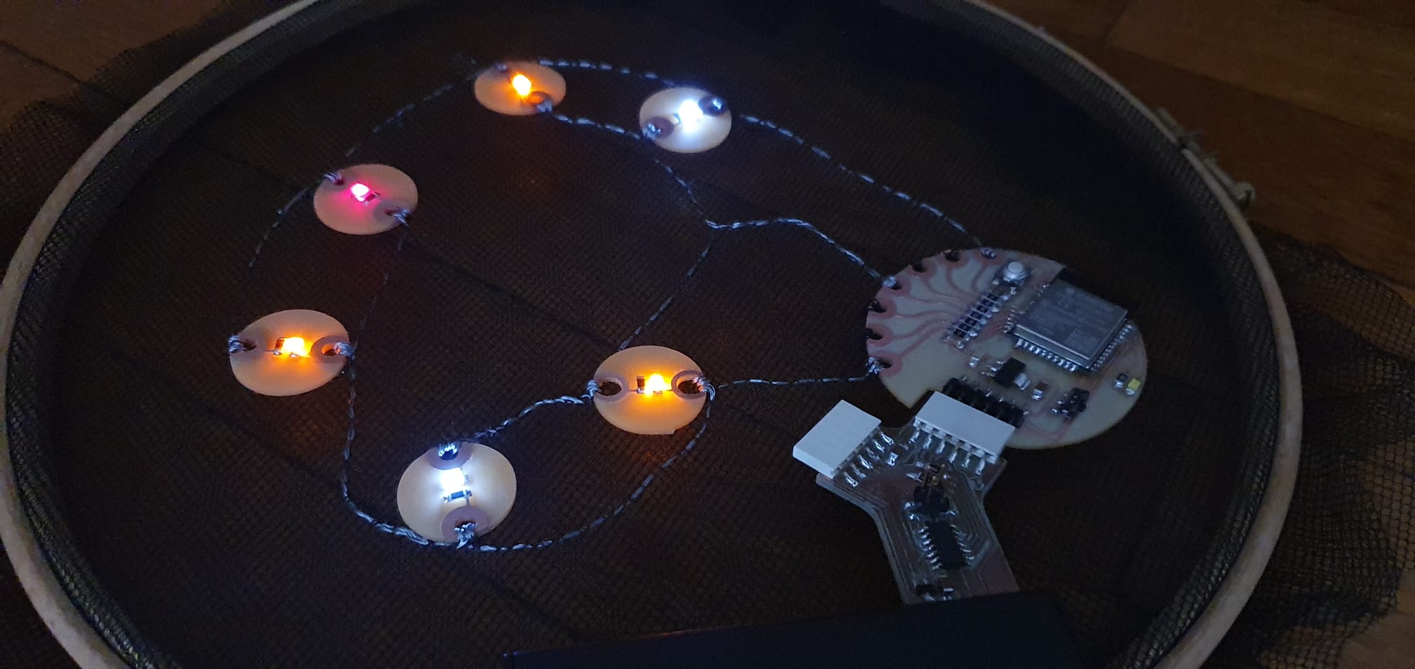
Charlieplexing sewable LEDs
I wanted to charlieplex with the sewable LEDs I made, and the first spiral is to get 6 to work. I found this page which outlines it neatly and I used their schematic: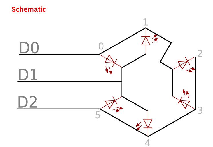
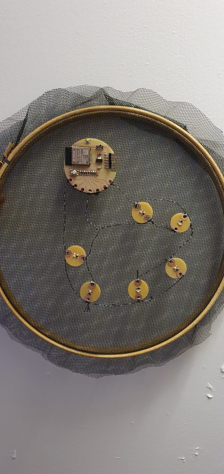
I started sewing the PCB first, where I used non-conductive thread to stitch down the pads I wasn't going to use. Then I started making paths from each pad on the PCB to the LED.
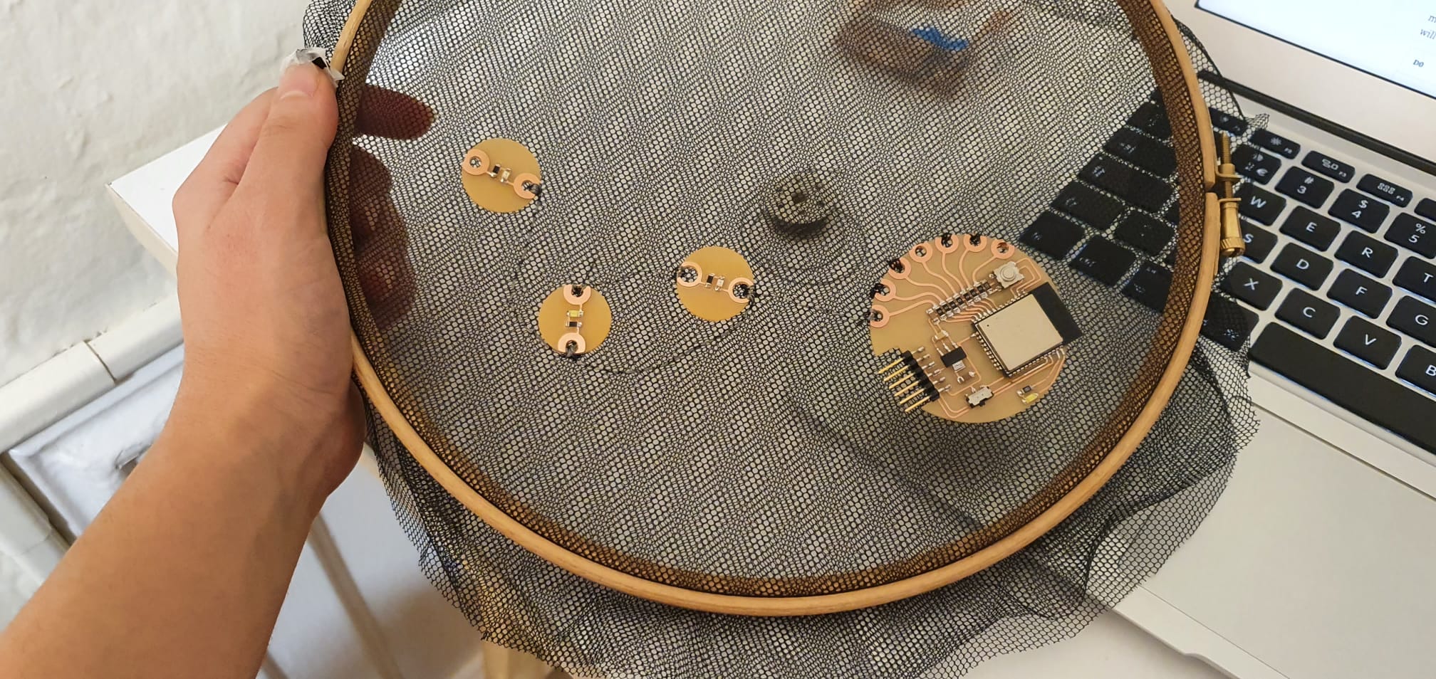
In the end, this is how it came to be:
For the programming, I used this code that I found from this kind person on the internet:
/* Charliplexing 6 LEDs
--------------------------------------------------------------------------------
Row 1 (R1): Pin 32
Row 2 (R2): Pin 33
Row 3 (R3): Pin 25
--------------------------------------------------------------------------------
variable    pinMode      state
L           OUTPUT       LOW
H           OUTPUT       HIGH
Z           INPUT        LOW
---------------------------------------------------------------------------------
	R1 (Pin 32)      R2 (Pin 33)     R3 (Pin 25)
L1    L                 H                Z
L2    H                 L                Z
L3    Z                 L                H
L4    Z                 H                L
L5    L                 Z                H
L6    H                 Z                L
-----------------------------------------------------------------------------------
LED    Cathode      Anode
1         R2          R1
2         R1          R2
3         R3          R2
4         R2          R3
5         R3          R1
6         R1          R3
---------------------------------------------------------------------------------
*/

const int LED_1 = 32;     //LED row 1
const int LED_2 = 12;     //LED row 2
const int LED_3 = 26;     //LED row 3

void setup()
{
}

void loop()
{
//turn on LED L1
pinMode(LED_1, OUTPUT);     //row 1
digitalWrite(LED_1, LOW);
pinMode(LED_2, OUTPUT);     //row 2
digitalWrite(LED_2, HIGH);
pinMode(LED_3, INPUT);      //row 3
digitalWrite(LED_3, LOW);

delay(1);

//turn on LED L2
pinMode(LED_1, OUTPUT);     //row 1
digitalWrite(LED_1, HIGH);
pinMode(LED_2, OUTPUT);     //row 2
digitalWrite(LED_2, LOW);
pinMode(LED_3, INPUT);      //row 3
digitalWrite(LED_3, LOW);

delay(1);

//turn on LED L3
pinMode(LED_1, INPUT);      //row 1
digitalWrite(LED_1, LOW);
pinMode(LED_2, OUTPUT);     //row 2
digitalWrite(LED_2, LOW);
pinMode(LED_3, OUTPUT);     //row 3
digitalWrite(LED_3, HIGH);

delay(1);

//turn on LED L4
pinMode(LED_1, INPUT);     //row 1
digitalWrite(LED_1, LOW);
pinMode(LED_2, OUTPUT);    //row 2
digitalWrite(LED_2, HIGH);
pinMode(LED_3, OUTPUT);    //row 3
digitalWrite(LED_3, LOW);

delay(1);

//turn on LED L5
pinMode(LED_1, OUTPUT);    //row 1
digitalWrite(LED_1, LOW);
pinMode(LED_2, INPUT);     //row 2
digitalWrite(LED_2, LOW);
pinMode(LED_3, OUTPUT);    //row3
digitalWrite(LED_3, HIGH);

delay(1);

//turn on LED L6
pinMode(LED_1, OUTPUT);
digitalWrite(LED_1, HIGH);
pinMode(LED_2, INPUT);
digitalWrite(LED_2, LOW);
pinMode(LED_3, OUTPUT);
digitalWrite(LED_3, LOW);

delay(1);
}