Assignments
The second task that we were given this week is:
- cut something on the vinylcutter
- design, lasercut, and document a parametric construction kit, accounting for the lasercutter kerf, which can be assembled in multiple ways, and for extra credit include elements that aren’t flat
Sticker (vinylcutter)
I had a few ideas in mind for what I would want to cut out using the vinylcutter. I wanted to cut out a sticker that I could then put onto my laptop.
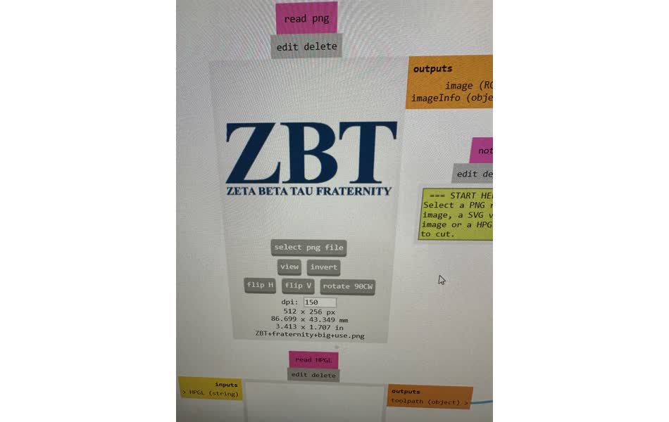
The first idea I had was to design a logo for my (on hiatus, not defunct) startup, Bestie Bowls. However, given the lack of a purple color to choose from (the colors they had were white, black, blue, yellow, red), and the fact that I know nothing about visual design, I thought that I would instead go with my second idea, which was to just print out the logo of my frat, ZBT.
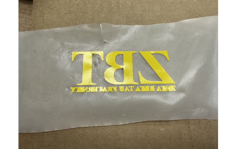
So my search began on Google, where I found only a handful of good contenders, all of which were pretty low resolution. I ended up choosing this one:
![]()
I didn’t care about the “ZETA BETA TAU FRATERNITY” text at the bottom, since there wasn’t enough resolution to get good vectors on those anyways, and because it’s pretty redundant. So I just ignored the bottom of it.
I forgot to take pictures during the earlier steps of the process, but I have summarized the steps here:
- Find a picture to vinyl cut, and make sure that it is in a png format
- Open mods, right click, go to programs, scroll down until u get to the vinylcutter, and open it.
- Upload the image, and set the ppi of the output, which determines the size of the cut. Pay attention to pixel density though. The image I used was low resolution, so it is important to make sure that the ppi is high enough that it does not come out blocky.
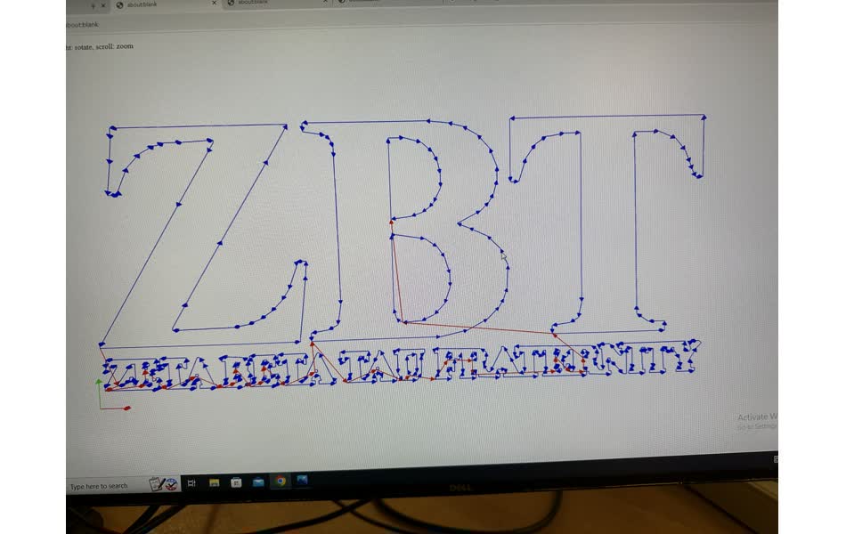
- Set the white/black threshold for the edge detector to an appropriate value for the image.
- Press the calculate button somewhere in the middle of the graph to generate the vectors. Check that the vectors look good.
- Make sure the vinylcutter is connected by pressing the connect to device button.
- Finally press send to device to start cutting. (but you should only do this after you’ve done the next steps first)
Now for the steps to load the vinyl:
- Grab a roll of vinyl and slide it into place on the vinylcutter.
- Align the cutting head to one of the white spots on the row
- Lock the vinyl into place.
- Press the “set origin” button on the machine, so that it cuts where u want it to.
After cutting, there is a nice process for sticking the vinyl to something, in my case, the back of my laptop.
- Cut out a piece of transfer paper large enough to cover the part of the vinyl that you care about. And put it onto the face of the vinyl.
- Slowly peel back the backing of the vinyl. Do this by rolling the vinyl away, with a small radius, so that there are more shear stresses and not tension. Use a pair of tweezers to help keep the parts you care about on the transfer paper, and to help pull off the parts that you don’t care about.
- Use the tweezers to fix the edges and remove any leftover bits of vinyl that shouldn’t be there.
- Paste the vinyl onto another surface, with the transfer paper holding all of the pieces in place.
- Make sure that the vinyl is in place, and then remove the transfer paper on the back, so that the vinyl stays behind.
- Breathe a sigh of relief now that its done!
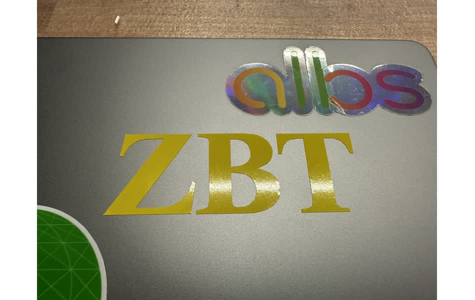
After all of the steps, it looked like this on my laptop!
Cardboard laser cutter
For some reason, everytime I visit a new place, I feel obliged to get a souvenir in the form of a shot glass. Not sure how this began, but it has sort of become a thing that I do, and is a good way to remember the places that I’ve visited.
The problem: I now have something like 20 shot glasses in my room, scattered haphazardly in different places.
The solution: A little stand/shelf for my shot glass collection would be a great way to keep them all in one place and organized, and so I thought it would be pretty fun to make a mini shelf out of the cardboard.
So I went ahead and started designing it in fusion. Since I will be laser cutting the entire thing out of cardboard, I am able to just draw everything out in a 2D sketch. This is nice because I am a newbie at CAD, but I’m good at picturing how things fit together in my head.
One of the requirements for this assignment was to make everything parametric. This definitely took a bit of extra initial time, but as the number of parts in my assembly increased, it really started helping out, since I could just enter in a name for a length instead of having to remember a bunch of values. And it made it really easy to put in placeholder values for dimensions I didn’t know at the time, like the dimensions of my shot glasses, the wdith that I should use for a press fit, and the kerf.
With parametric design, I was able to put in a variable name for a length, and then replace it later when I get the actual value. This also required adding more constraints to the design, so that when I changed a parameter, it wouldn’t mess other stuff up, but this allowed me to really think deeply of the relationships between the parts in my design.
I have used Rhino in the past for an architectural design class, and I have to say that using the parametric design in Fusion 360 did save a lot of time as the number of parts increased.
From our group project, I was able to add in the values I was missing: a good width of a press fit is either 0.155” 0.160”. I used .155” in mine. The kerf, the diameter of the laser at its focal point, is .01”. The value I was using for kerf was the radius, or how much I would have to offset my line from where I actually wanted it to be, so in my parameters, it was .005”.
After getting the finished sketches, the next step was to prepare it for the laser cutter. The first step is to extrude all of the sketches, which I was initially confused about. However, it’s good practice to do this, because sometimes sketches will have construction lines that would be exported, and sometimes it will have overlapping lines, which would cause the laser cutter to go over a line twice, and extruding it wipes out these extra lines and is just a really easy way to ensure that the lines are clean. I extruded all of the parts to .15”, so the 3D rendering would actually very closely resemble the final product.
The next step is to create a new sketch on the same plane as the extruded faces of the bodies. I then pressed ‘p’ to open the projection function, which allowed me to project all of the faces onto my new sketch just by selecting them. I then exported this as a dxf and put it on a usb drive.
I plugged this into the machine controlling the laser cutter, and opened the dxf file. Here, I highlighted all of the lines, and ensured all of the line thicknesses were “hairline”, and changed the color of all of the lines to red (not sure why exactly this is necessary, but Anthony ensured me that it was).
Then, I pressed Ctrl+P to open the print dialog. There I specified that I would be printing in red, and it was here that I also went to the manual power settings tab. There, I entered in the optimal power/speed/dpi settings for cardboard, which our group found it to be 100% power, 15% speed, and 500dpi.
Since my cardboard was bowing out in the middle, the focus was hard to get right. I ended up setting the focus to align with the middle, which meant that the edges did not cut out perfectly, even after I ran the job twice.
I ended up using a utility knife to finish the cuts for the parts that didn’t fully cut out.
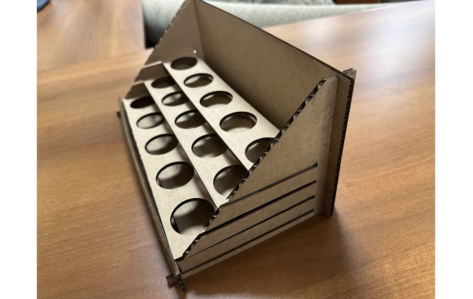
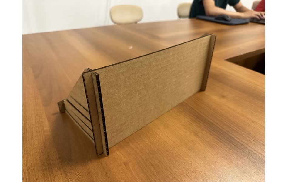
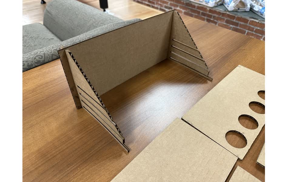
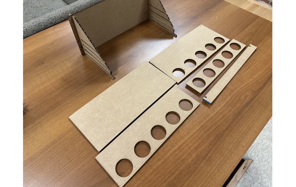
I forgot to take a picture of the pieces before I started assembling them, but here are some pictures of it partially assembled:
And here are some pictures of what it looked like when fully assembled.