Assignments
The individual assignments for this week are:
- make and test the development board that you designed to interact and communicate with an embedded microcontroller
PCB Design
After talking to Anthony, I learned that there were a lot of changes that I had to make in order for my PCB to actually be printable/able to do things.
Importantly, I needed to have headers so that I could break out all the pins I wasn’t using for the dev board, but also have them be available for future use.
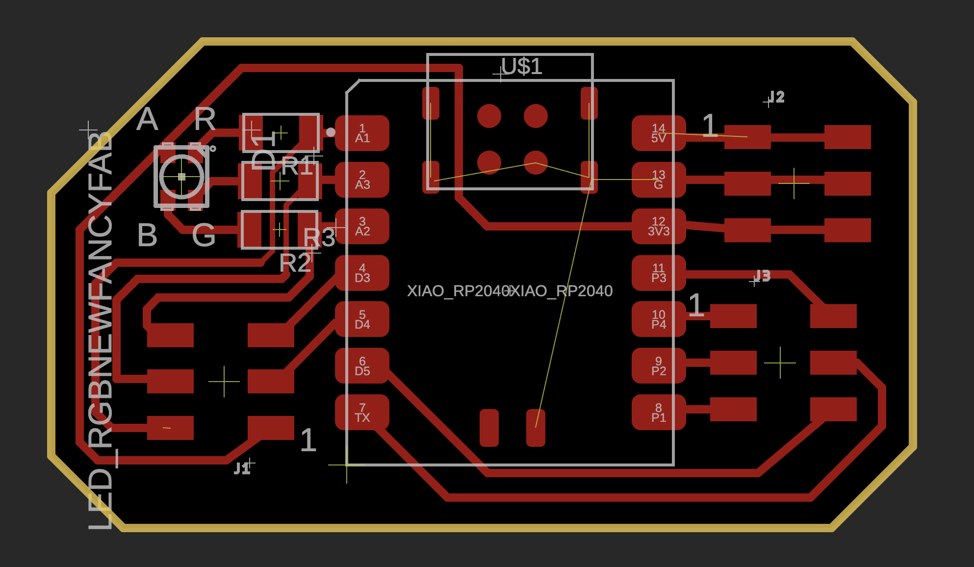
The final design that I had for printing looked as follows:
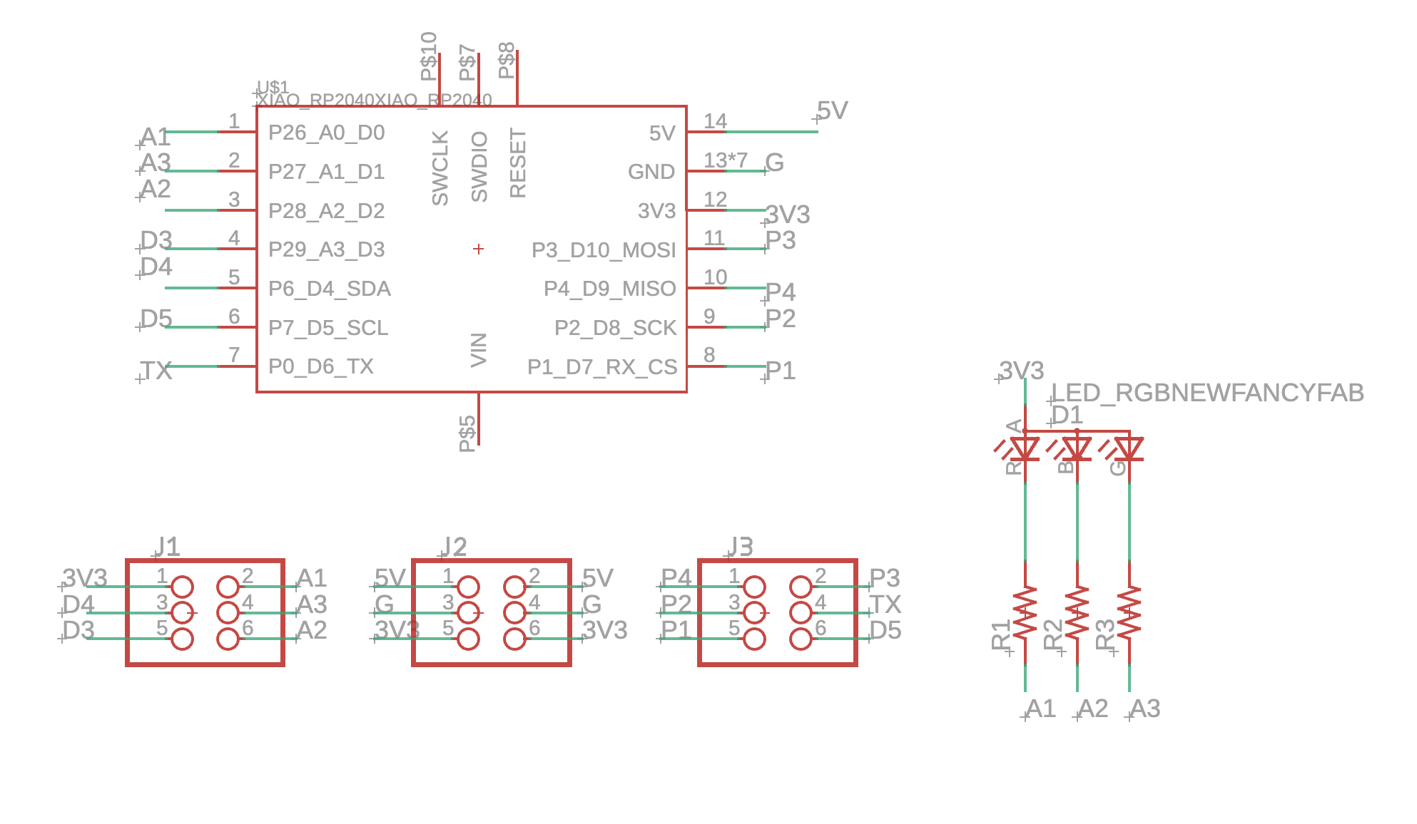
And the final PCB looked like this
Milling the board
To prepare the file from Fusion 360, just export it as a .brd file and put it on a usb drive.
The mill that we use is a Other Mill branded end mill. The software that I opened the .brd file in was Bantam tools.
To attach the stock to the mill, use three pieces of double sided tape to firmly attach the stock. If doing a double sided pcb, then I would alos have to use a bracket.
In bantam tools, I needed to specify the position of the board, the position of the stock, and the tools I will be using. We have a 1/32in PCB tool and a 1/64in one, which should be specified (the 1/32 in tool can save time on coarser cuts, while the 1/64in tool is useful for finer cuts)
I then load the proper tool and specify it in the softwware, and switch it out when the software asks.
To switch out a tool, use the two wrenches to grab the spindle high and low (the smaller wrench for the higher flat side). Use my left hand to hold the smaller wrench, and my middle finger on that hand to press against the tool so that it won’t just fall out. I loosen the holder the rest of the way by hand.
To attach the other bit, I slide it in the hole, close ish to all the way in, and screw the holder tight, and finish the tightening with the wrenches.
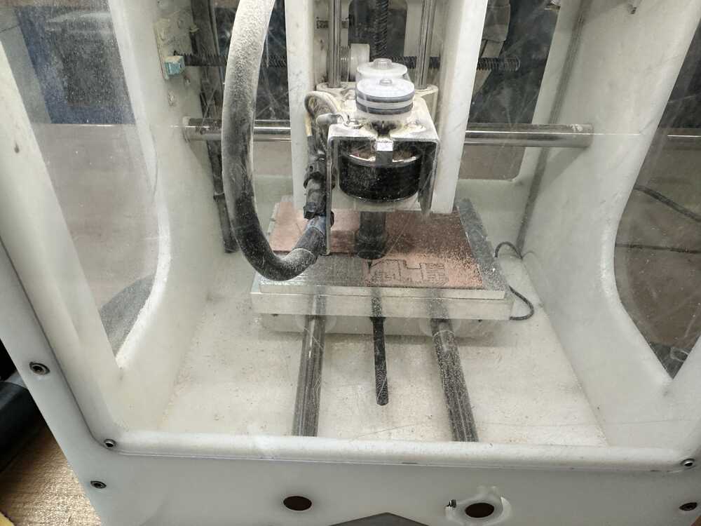
I then press start to get the milling started, and watch it go.
This is what it looked like during the milling process
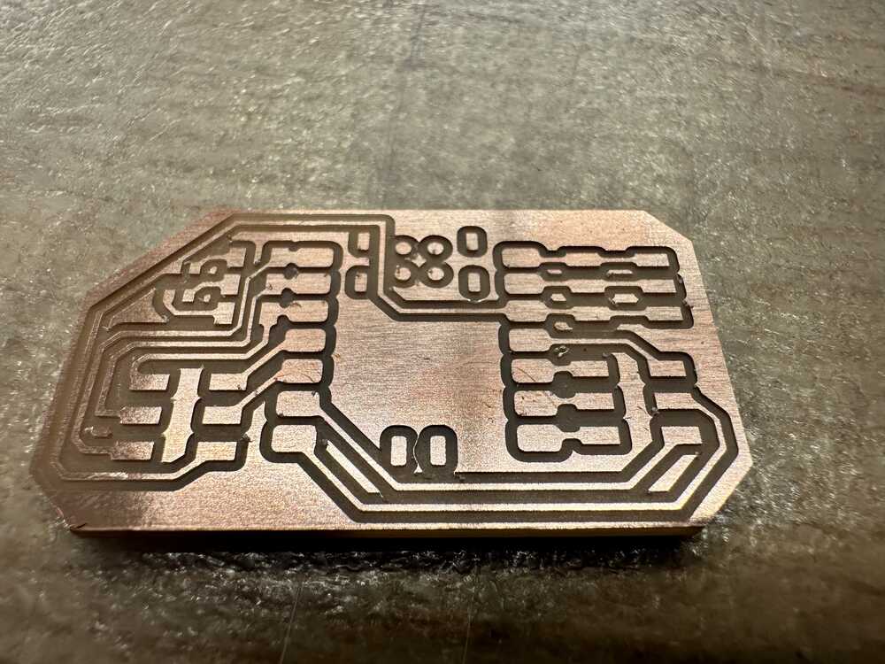
Once the job is finished, I used a spackle knife to pry the pcb off of the bed. I also visually inspect the board for burrs (which occur if the tool is brand new, or if it is getting dull) and tiny copper lines that should be removed. I can rub the spackle knife against the surface to remove any burrs and use tweezers to remove any tiny wires.
This is what my PCB looked like after being milled.
Soldering onto the board
The next step is to solder my parts onto the board.
First, I had to collect the parts. The EDS lab doesn’t have any 3x2 headers, but it does have 5x2 headers, which can be cut down to 3x2 pretty easily, which is what I did.
I also used 1k Ohm resistors for the current limiting resistors for the LED.
The steps are as follows:
- “Tinning”: Put the iron on a pad, wait 3-4 seconds for the pad to heat up. Then add some solder to coat or “tin” the pad.
- Pick up the component with the tweezers in my left hand. Put the iron back onto the tinned pad to melt the solder, then place the component onto the melted solder. Remove the iron, and then let go of the component once the solder freezes. The component should now be attached in place.
- Solder all other pins: Put the iron in contact with both the pad and the wire that I want to solder together, so that they’re both heated. Feed the solder onto the hot wires, not the iron itself. The solder should automatically coat itself over the surfaces. Make sure that the join is shiny and not lumpy, which generally means there is a good connection. (do the original tinned joint after other ones have been soldered.)
- Use a multimeter to check that all traces are connected correctly.
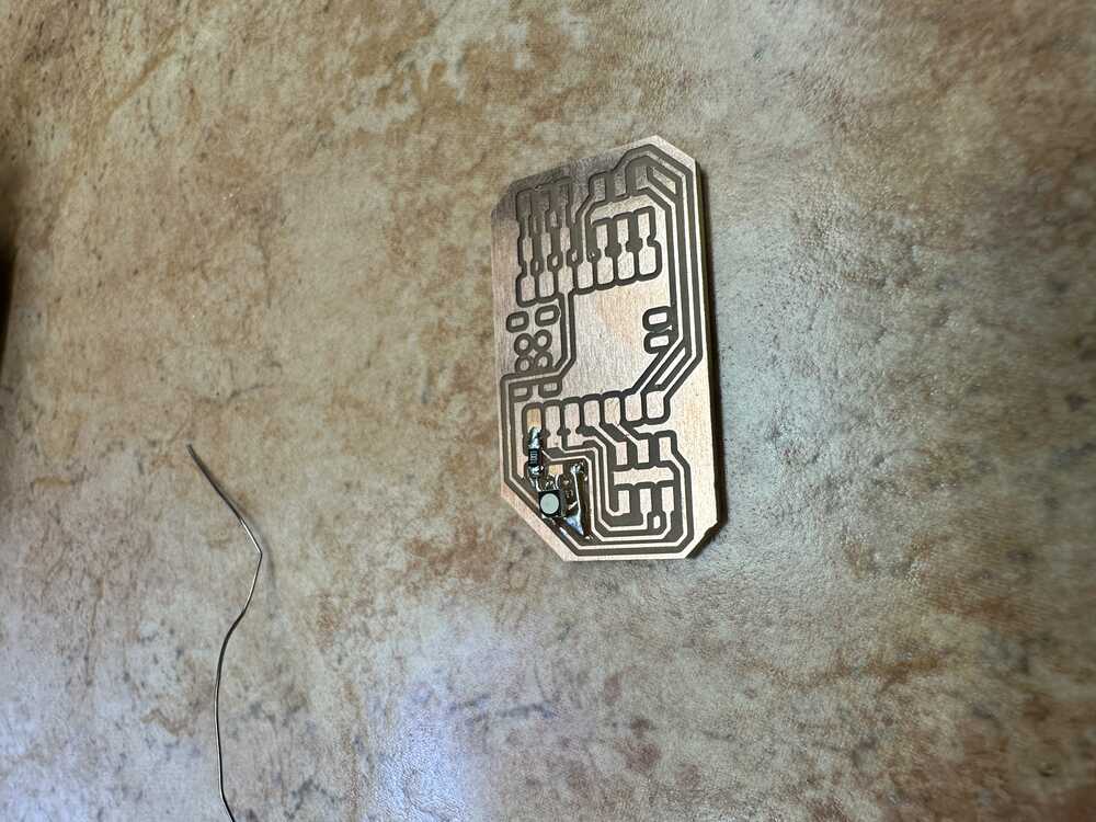
This is what my board looked like at an intermediate stage. It looks a bit weird because the footprint for the LED in the Fusion 360 library seems to be incorrect. As a bit of a hack to get it to work, Anthony ended up using a wire to jump the gap between an isolated copper section and the pad for the resistor, and I finished by connecting the copper section to the contact on the LED.
Update: it turns out that I had the rotation of the LED wrong, and thus later I had to remove the LED and resolder it rotated, and it fit perfectly on the traces. This was a good chance to learn how to use solder wick to pick up the excess solder once the LED was removed.
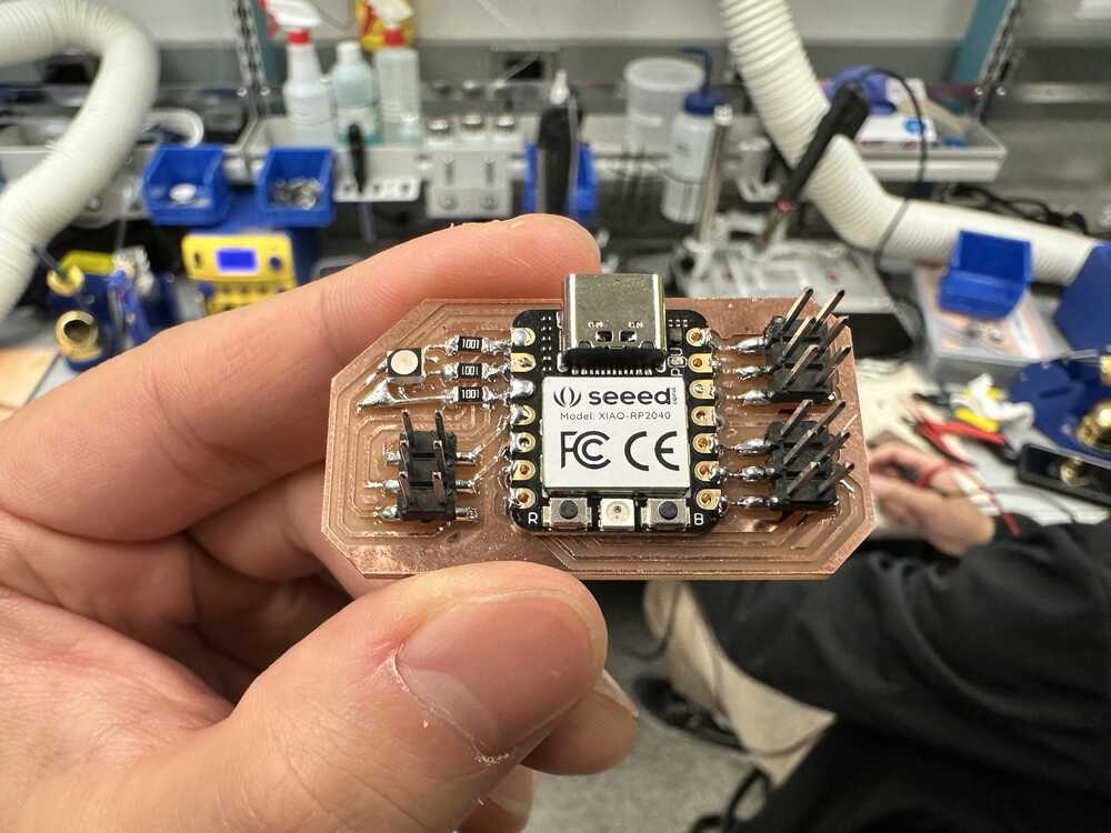
This was the final board after all components were soldered.
Appendix:
Fusion file I2C Controller Scanning Code I2C Controller Receiving Data Code I2C Peripheral Send Data Code