Week 6
Things I did this week:
- Characterize the design rules for your in-house PCB production process
- Make and test the development board that you designed to interact and communicate with an embedded microcontroller
Characterize the design rules for your in-house PCB production process
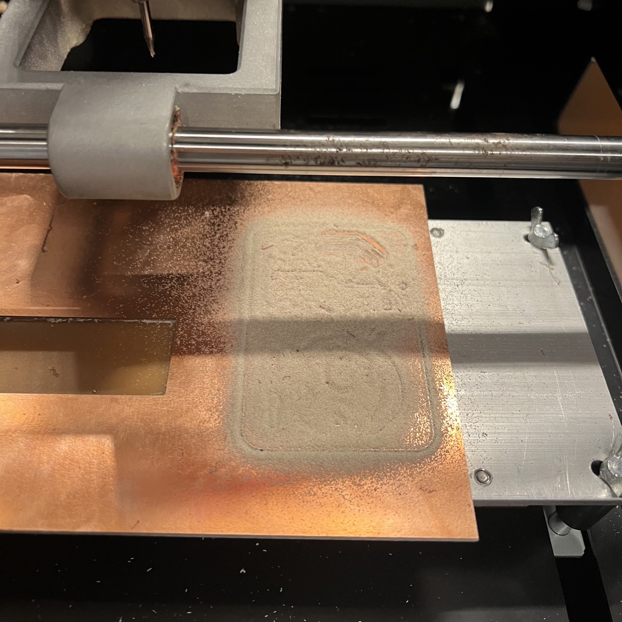
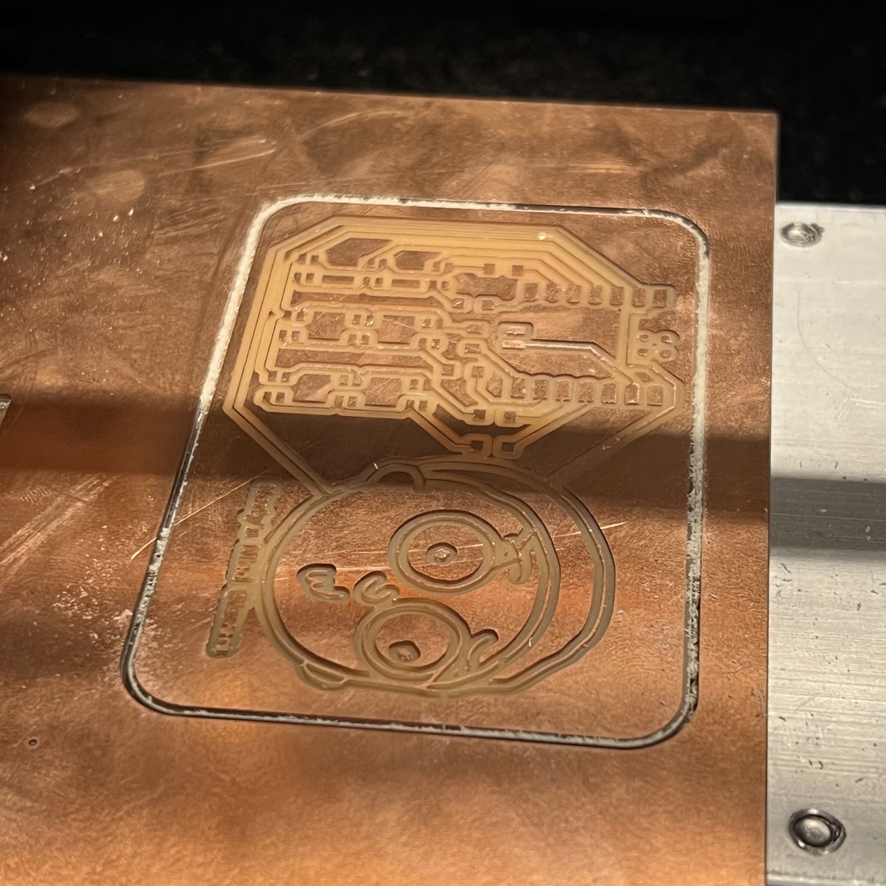
We did this during the weekly training together as a group. We used the Roland monoFab SRM-20 Compact Milling Machine. The whole process took way longer time than expected, the machine kept throwing errors, and finding an appropriate screw driver took a long time. The result looks nice. We can see that the gaps need to be at least 0.016 inches, and the lines need to be at least 0.010 inches. In practice I think 0.400 mm is the minimum.
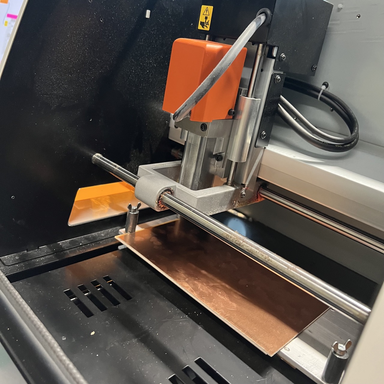 the machine
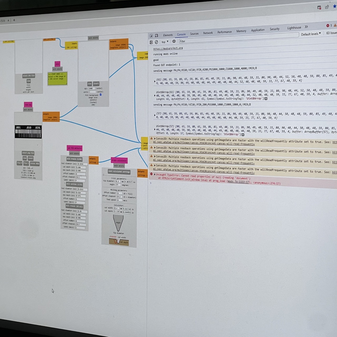 calculating paths
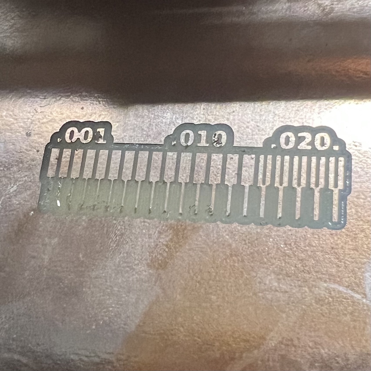 finished cutting copper
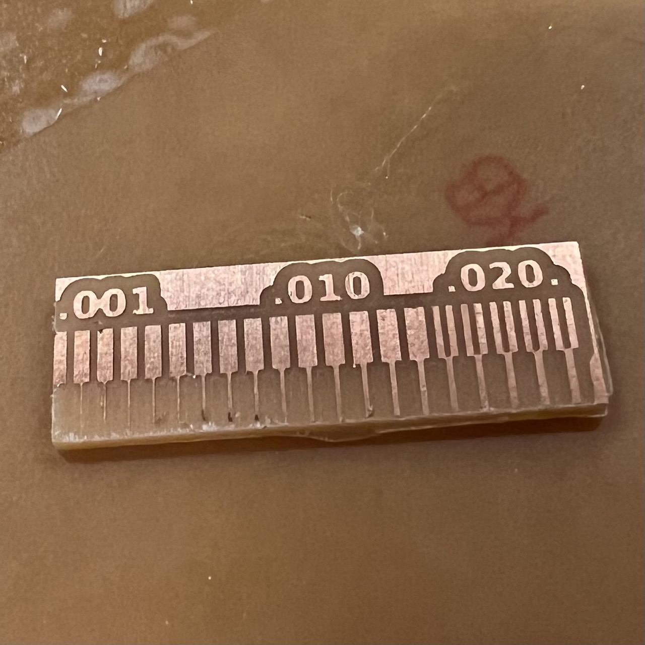 finished cutting out the board
Make and test the development board that you designed to interact and communicate with an embedded microcontroller
The Rick Board
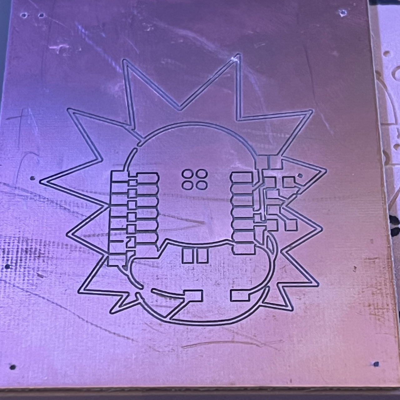
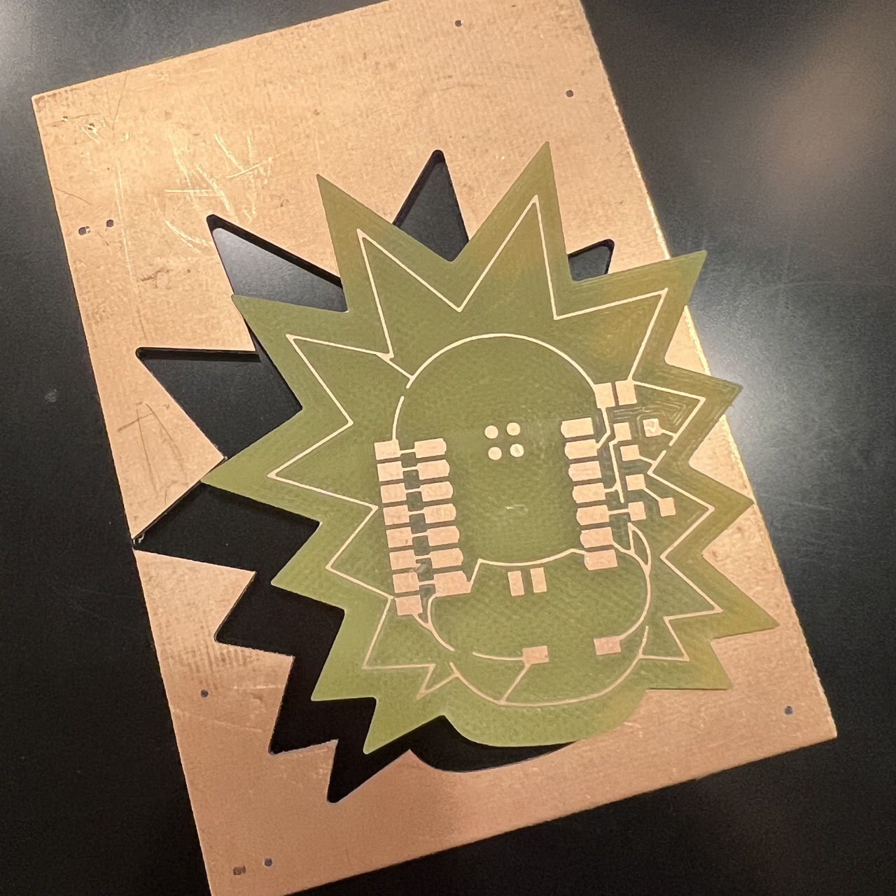
I first milled the board that I designed last week -- the Rick board.
I used Adobe Illustrator to create the outline of the board with help from Skye.
With help from Quincy and Lingdong, I milled the board in Quincy's studio on the really expensive 10k MODELA MDX-50 milling machine.
This machine can automatically switch its blades (super fancy!).
I'm very happy with the result. It turned out, however, the wrong board was used -- we used the ones for etching, and we were exposed to glass fibres during the process.
Morty's Mind Blowers (which was actually Catherine's Mind Blowers)
When I design the board last week, I didn't have any projects in mind. So I went on a designed a new board where I want to light up a matrix of LEDs.
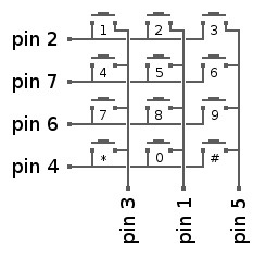 Quentin introduced me to the idea of multiplexing, where more than one LEDs can be controlled by one pin.
e.g. here if pins 2, 1, 5 are set to HIGH, and the rest are set to LOW, then only one will be connected.
Quentin introduced me to the idea of multiplexing, where more than one LEDs can be controlled by one pin.
e.g. here if pins 2, 1, 5 are set to HIGH, and the rest are set to LOW, then only one will be connected.image credit
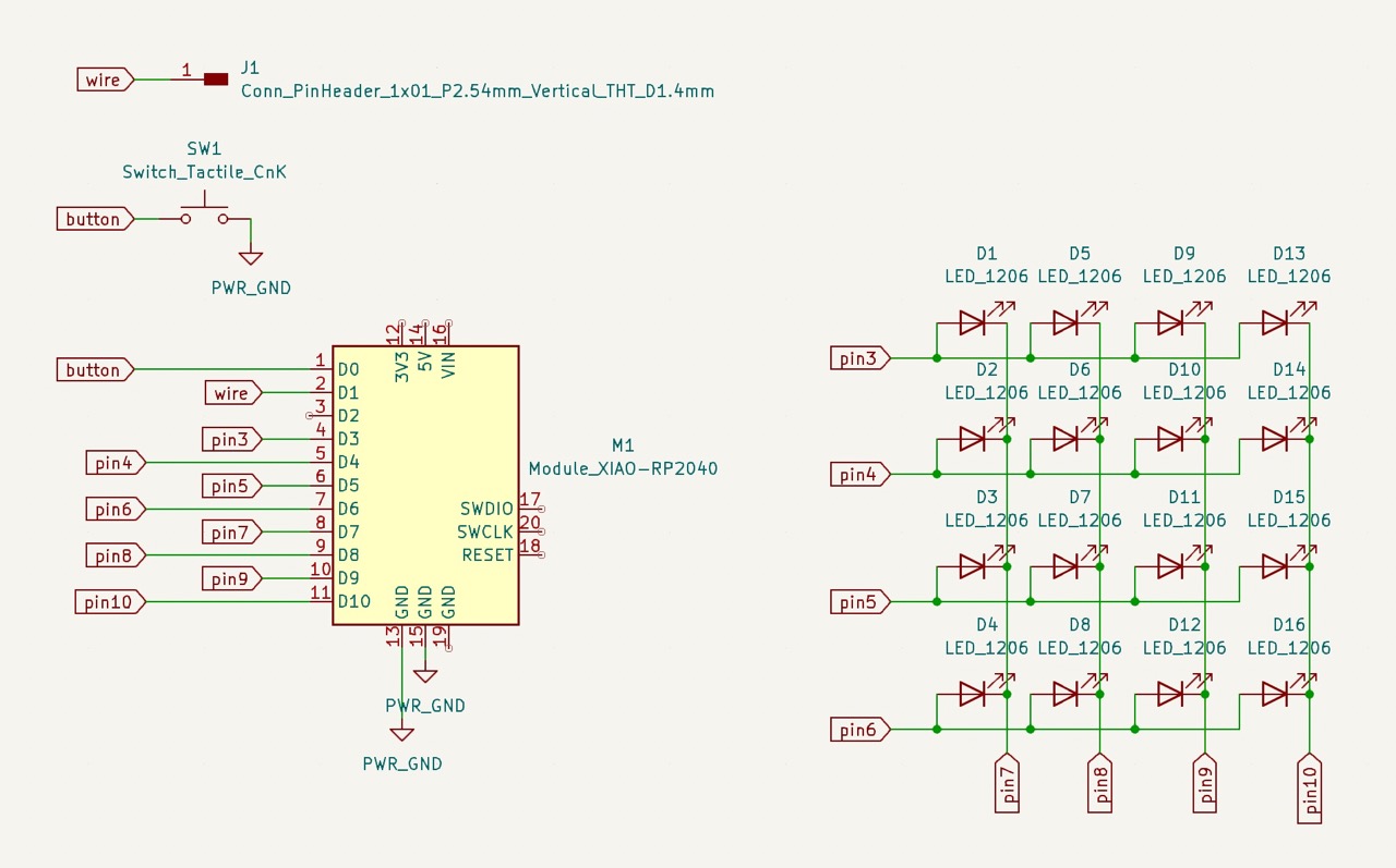 I then designed this circuit where I use 8 pins to control 16 LEDs.
The wire at pin D1 is for Adafruit_FreeTouch. While testing Adafruit_FreeTouch, Arduino suddenly cannot find the board,
so I followed this link to enter Bootloader mode.
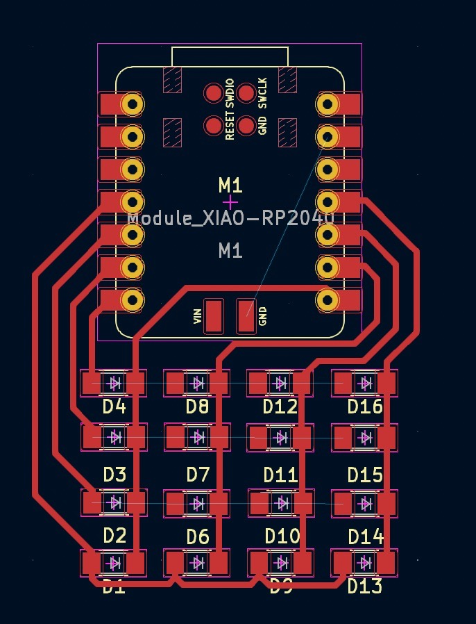
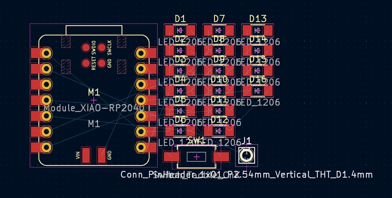 This is the chaos before I did routing, the picture on the right gives the result where there are a few places needing jumper cables.
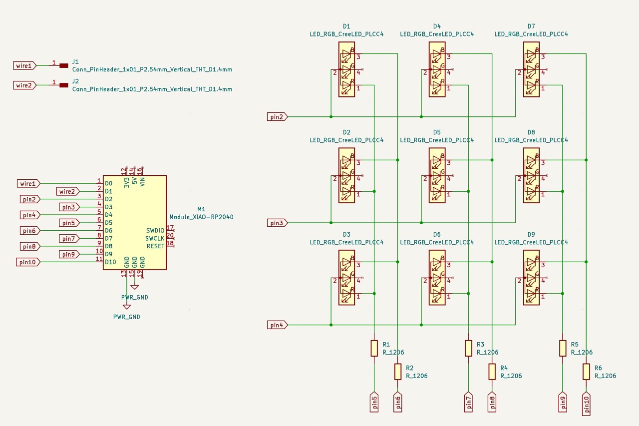 I then realized that I wanted to use RGB LEDs instead of regular white ones, so I switch the design.
And due to the limit on the number of pins, I had to reduce the size of the grid to 3*3.
I got inspired from Rick and Morty eighth episode of the third season -- Morty's Mind Blowers.
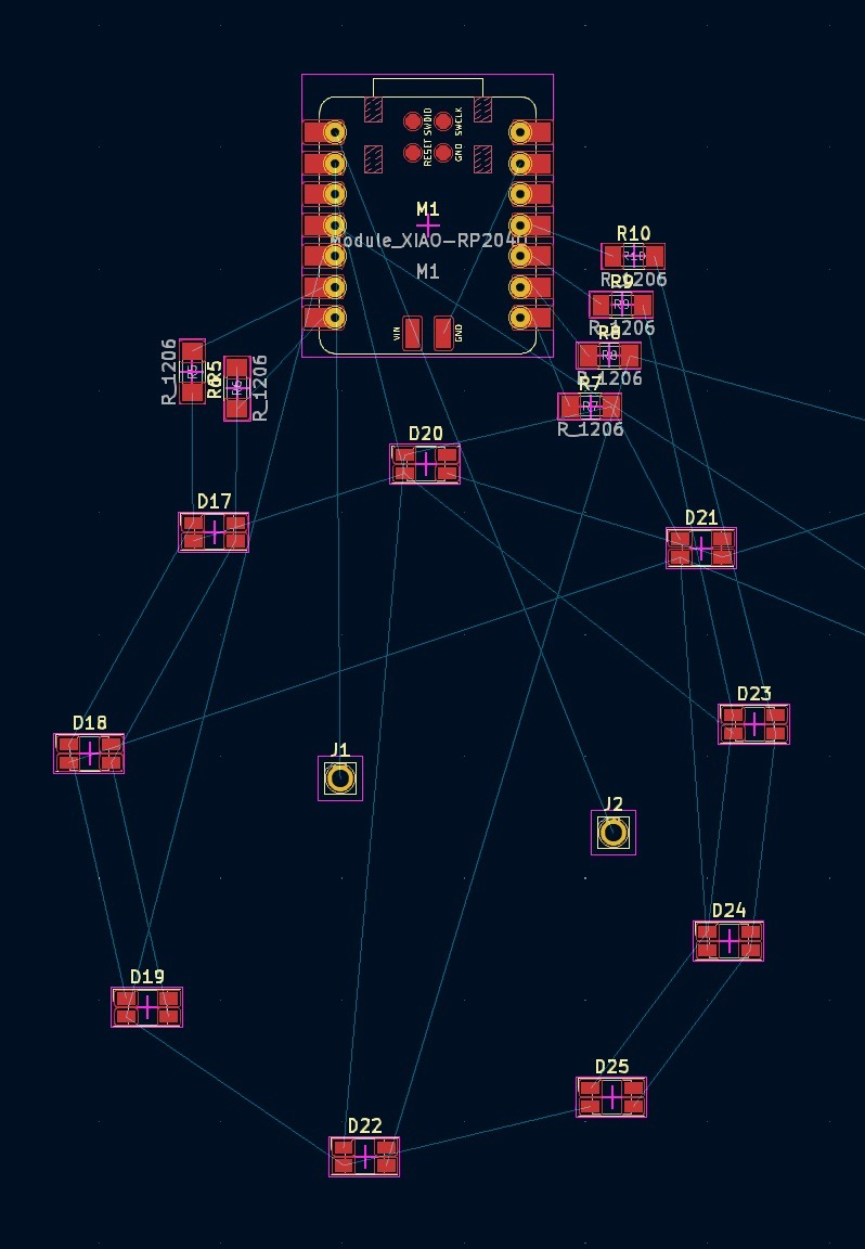 I tried to make the LEDs surrounding Morty's head.
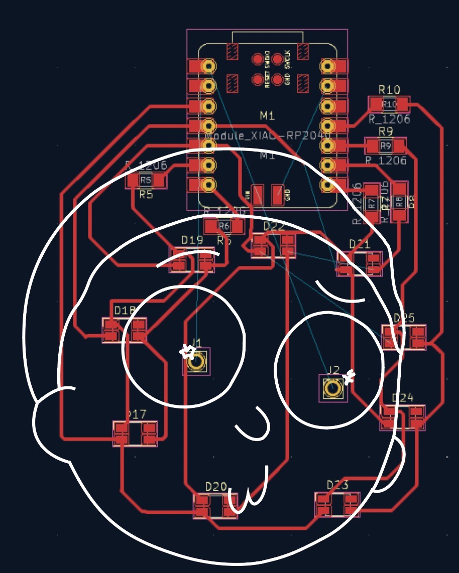 I tried routing, and then screenshoted that to Adobe Illustrator with Morty's outline.
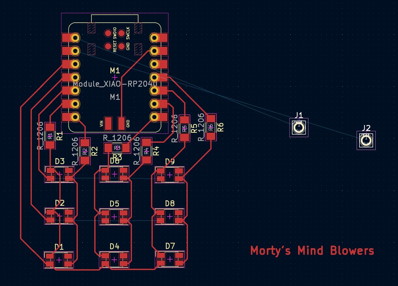 The previous approach was overwhelming, and I felt like it started turning into Catherine's mind blowers at this point.
So I switched to the previous easier design where I only use Morty's head for sensing.
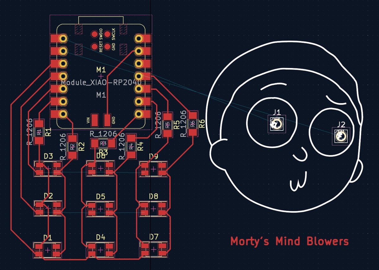 I added the design to Adobe Illustrator with Morty's outline to check the size of the board.
The idea is to poke his left eye and LEDs would light up in order and in red color, poke his right eye, and the color would be blue, poking both the color of LEDs will be purple.
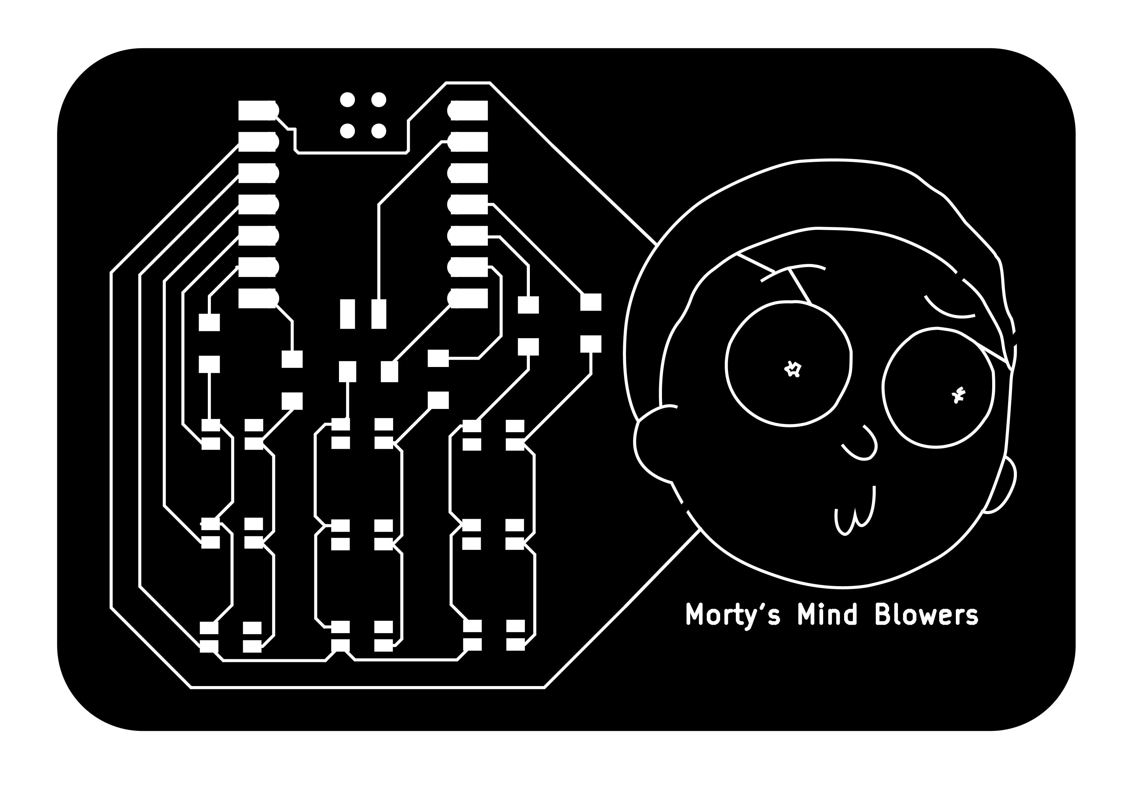 The finished circuit design.
 The finised board design.
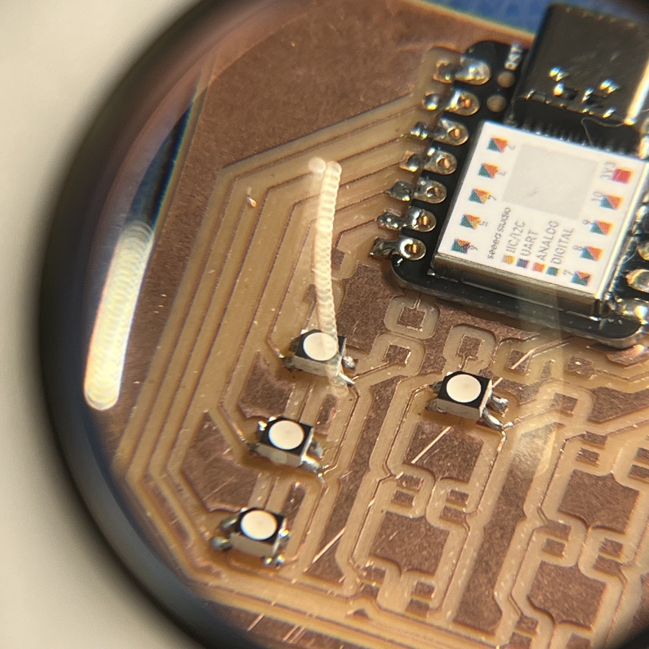
Milling took more than 1.5 hours, but in general it went smoothly. Soldering RGB LEDs took a lot of patience. They are so tiny and light, the solder would push the LEDs away from their spots. I also realized that astigmatism is a issue since I see two solders even though there's only one. I had to close one eye to see things clearly. One other thing is that there is not enough space for a jumping wire to connect to an anode (it's just too small!), I had to make use of the "leftover" copper and somehow make a jump between the LED anode and the "leftovers". Lingdong helped me a lot on connecting the jumping wires, at some part, 0 ohms resistors had to be used. We used multimeter to test the connections.
I then did a proof of concept to see if the connections actually works using Morty's eyes.
The LEDs supposed to light up in order, however as we can see from the top right video that only the bottom row lights up. After doing a lot of debugging with Lingdong, we found out that the XIAO SAMD21 board is broken (WHAT?). The issue was that pin 3 and 4 does not output voltage. We then attempted to remove the microcontroller from the PCB. Not surprised that it wasn't successful, the pins of the boards has large gaps and it was impossbile to heat them up at the same time. We also tried using the heat gun, while the solder barely melted, the glue between the copper and resin heated a lot more causing the copper sheet almost detaching. At this point I officilly managed to destroy my XIAO SAMD21.
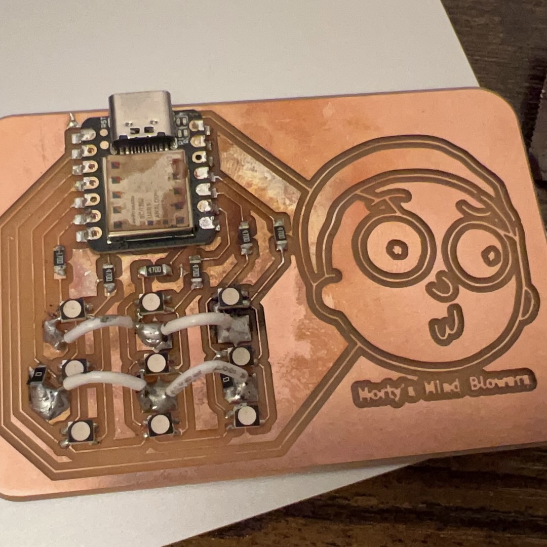 the destroyed board (looks kinda pretty(?))
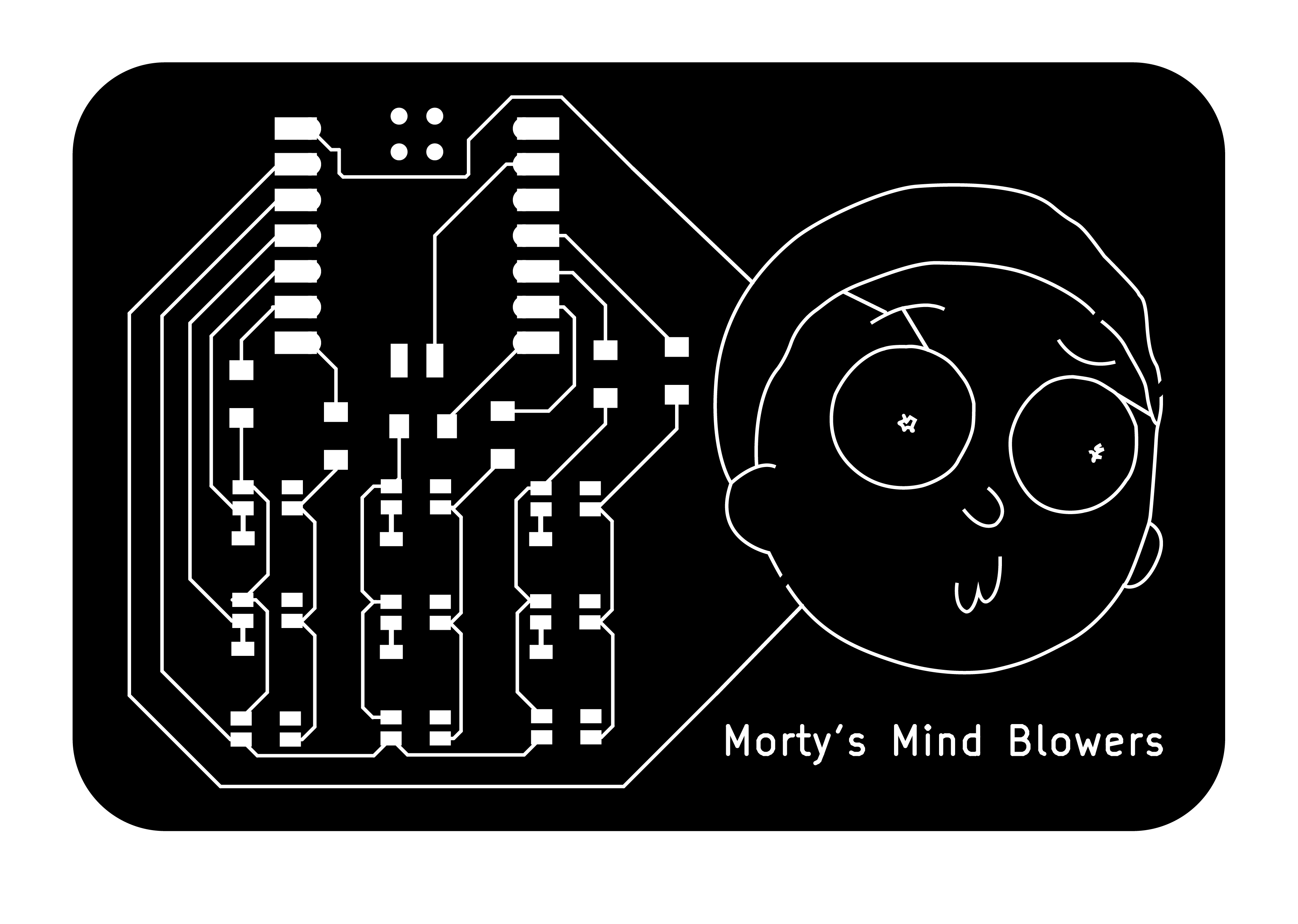 new design (added places for jumping wires)
Made a new board on Wednesday morning! And it went very smoothly! Everything just works at once. (Amazing that I finished before class)
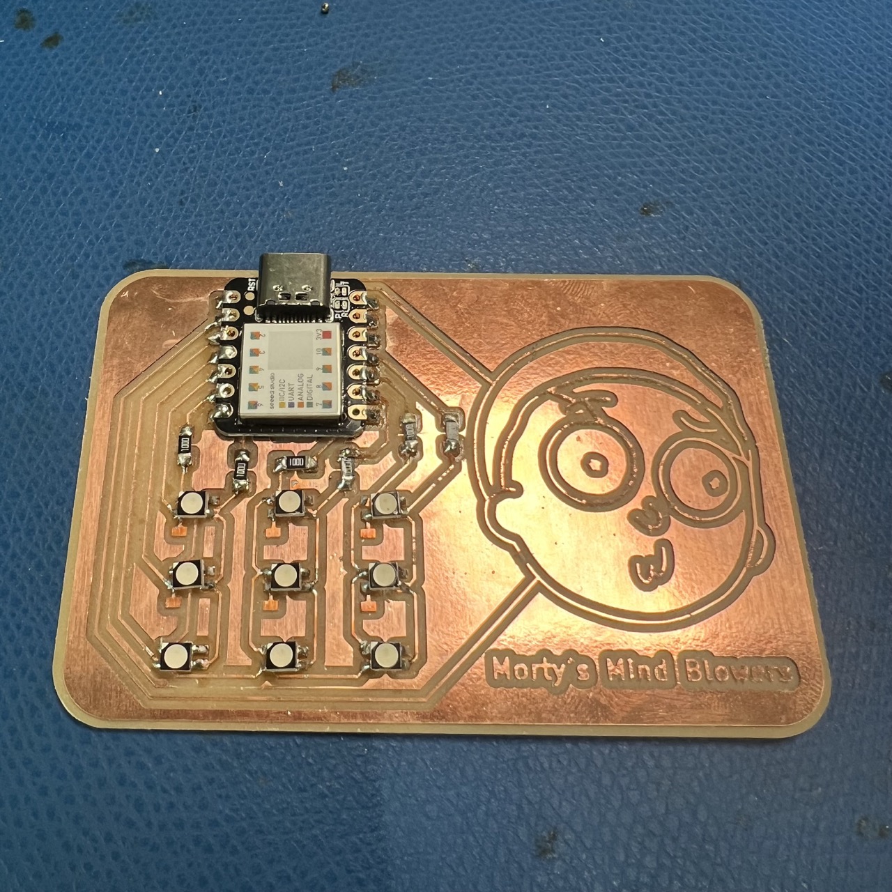 The only different components were the resistors.
I couldn't find any 470 ohms surface mount resistors in REEF.
I read the datasheet for the surface mount RGB LEDs,
where the forward current for R and B channel is 50 and 35 mA respectively. Since I'm outputing from the pins 3.3V,
this suggests that the resisstance should be at least 3.3V/0.035A = 94ohms. So I decided to use the 100 ohms resistors.
(We only had 100 ohms and 1k ohms resistors, and I felt like if I use the 1k ones, the brightness might be too low.)
The new design (small pads for jumping wires) made soldering way easier than before, and I didn't have to use additional 0 ohms resistors to overcome jumps.
An unsuccessful try with vinyl cutters.
There's only one milling machine in the harvard shop. While waiting for the machines, I thought why not try the vinyl cutters as well.
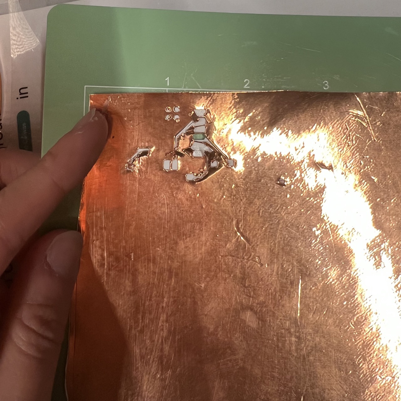 There were no available settings, so I first tried the same settings as aluminum foil. Immediately it cut through all the layers.
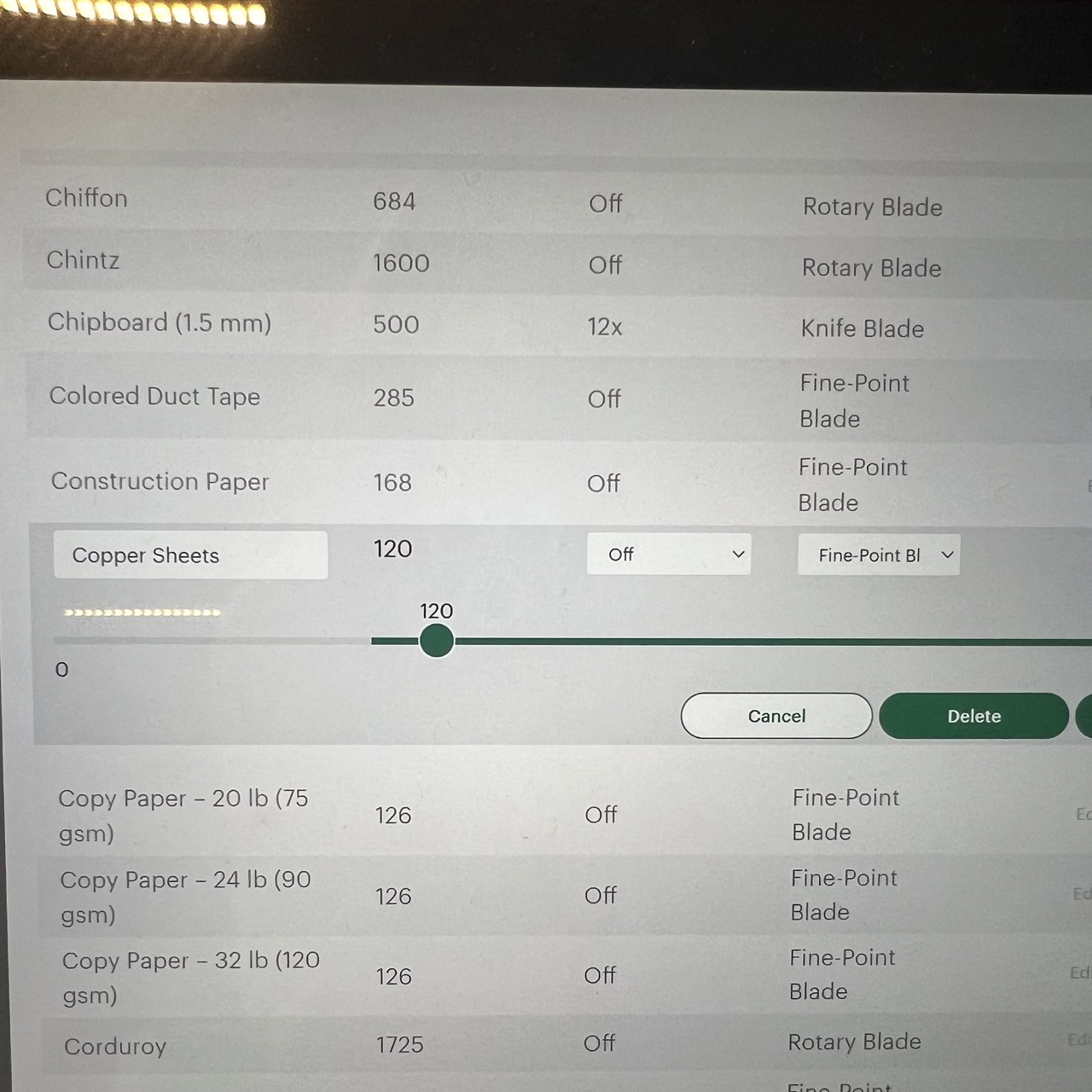 The page for adding custom materials. It turned out that it has to be the most gentle settings with less pressure.
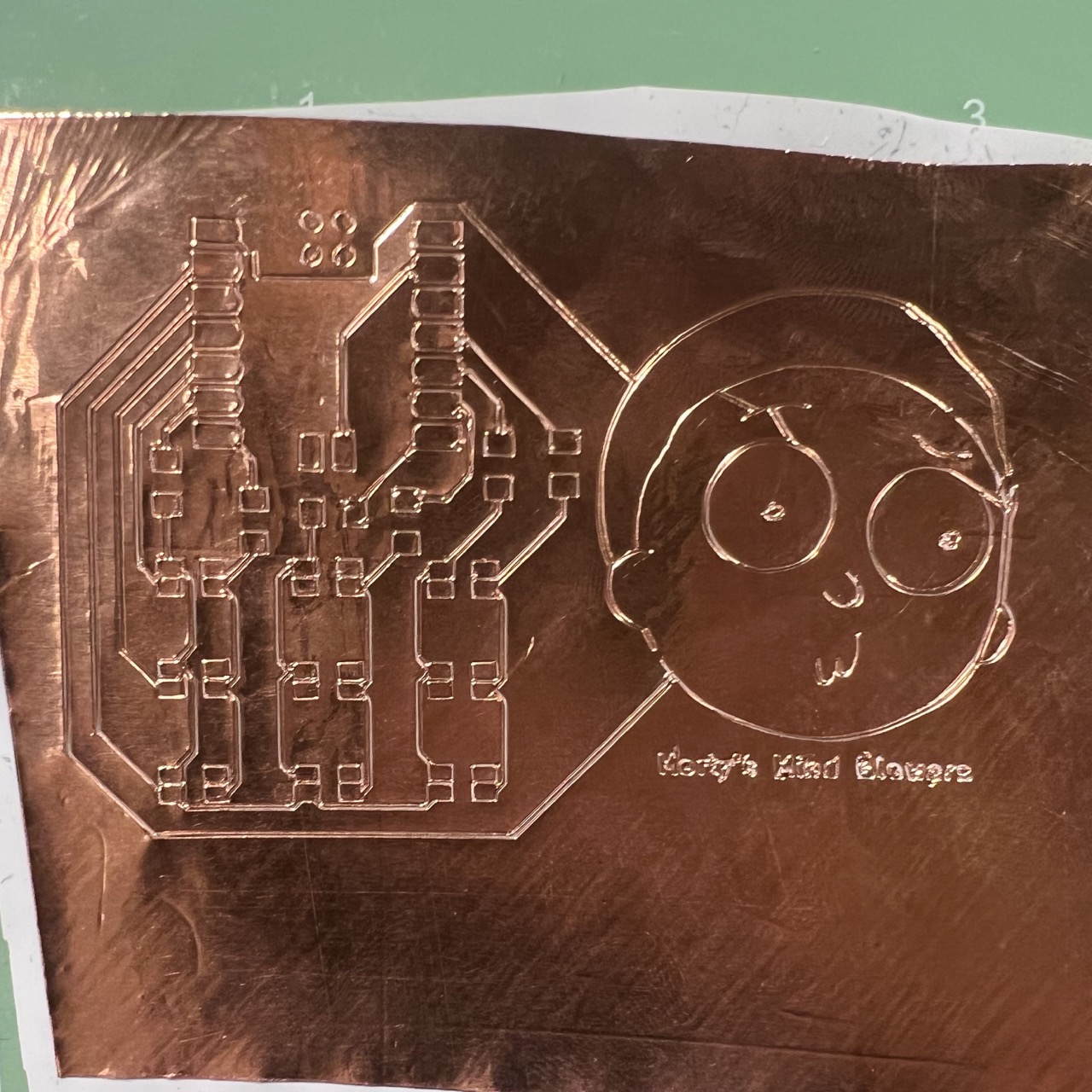 I sticked the copper onto a piece of vinyl since otherwise it detaches from the sheet right after the vinyl cutter cut it.
It looks fine but it wasn't really willing to separate from itself, and also I think my lines were too thin.