Week 1: CAD & Parametric Design
Final project proposal
My final project idea is a form of BCI where we couple the activity of a single neuron to reward. When the neuron fires, the mouse recieves a water reward. The goal is to test whether mice can learn to change or control the activity of a single neuron.
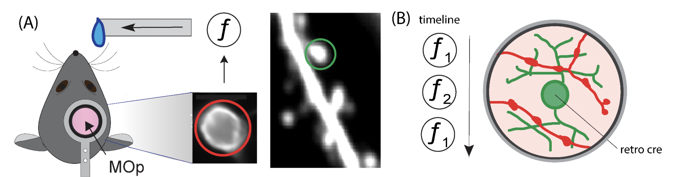
Figure 1 Single Neuron BCI Task (A) The activity of a single neuron in the primary forelimb motor cortex (MOp) is coupled to the lick spout via a transfer function f. The single neuron’s output activity will be reported in red, and the inputs from other neurons will be reported in green. (B) The presynaptic inputs to the BCI neuron will be imaged as the brain learns and transitions between different BCI transfer functions. The single neuron BCI is crucial to linking synaptic mechanisms to information encoding in neural circuits.
Week 2: Computer-controlled cutting

Vinyl cutting
First, I made a neuron vinyl cutout. To do this I searched for sillhouette images of neurons and downloaded the image. Then I imported it to Adobe Illustrator where I selected “outline as sillhouette” so that I could modify parameters such as the line thickness. This was important since I was miniaturizing the neuron sticker, I needed to make the lines thicker to print properly. Then I uploading a png to the mods app which was super user friendly. I made tons of stickers to give to my labmates and friends!
Week 3: Embedded Programming
I chose to use this week to document my mouse behavior circuit and how I talk to my arduino :-)
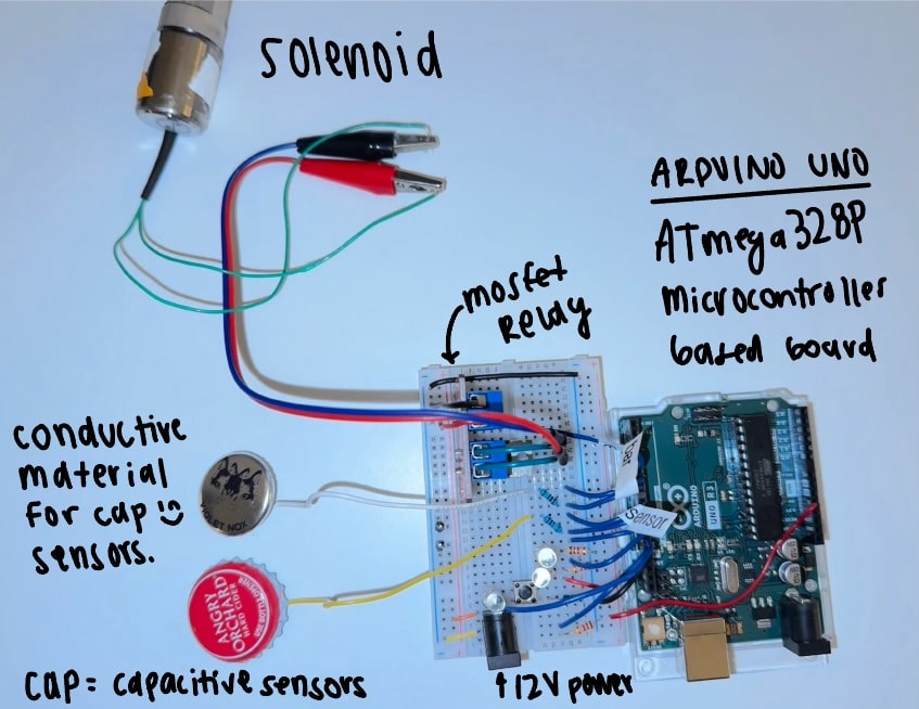
I used the simulation to learn how to add a button to my circuit. Here when the button press is detected by the arduino it turns on the LED pin. In my case, the button should open the solenoid for a fixed amount of time determined by the code onboard the arduino uno. I already have a pin sending to signal pin of relay that opens solenoid, so instead of changing LED_PIN i will change the SOLENOID_PIN when the button is pressed to open solenoid valve.
Week 4: 3D Scanning & Printing
I first though about printing a snowglobe, but when text-to-cad failed to make a suitable object I moved on. I considered a microscope, a mechanical bic pencil, a bird whistle, and a lock-and-key. I searched for avialable cad files and happened upon this cool link of inspiration for printing a combination lock. If printed in one piece, I would say this is an object that cannot be made subtractively. However, this was printed piece by piece sorry!
Week 5: Electronics Design
This week I followed this tutorial
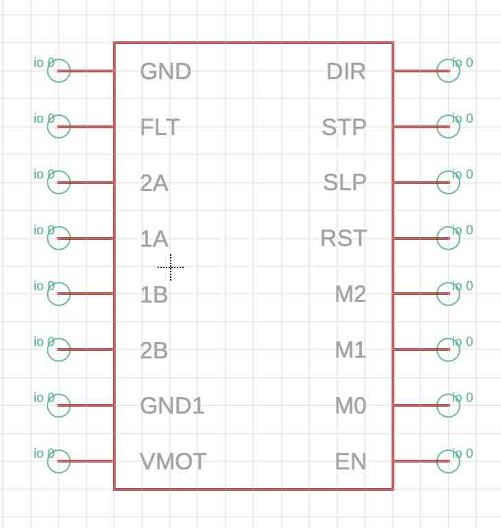
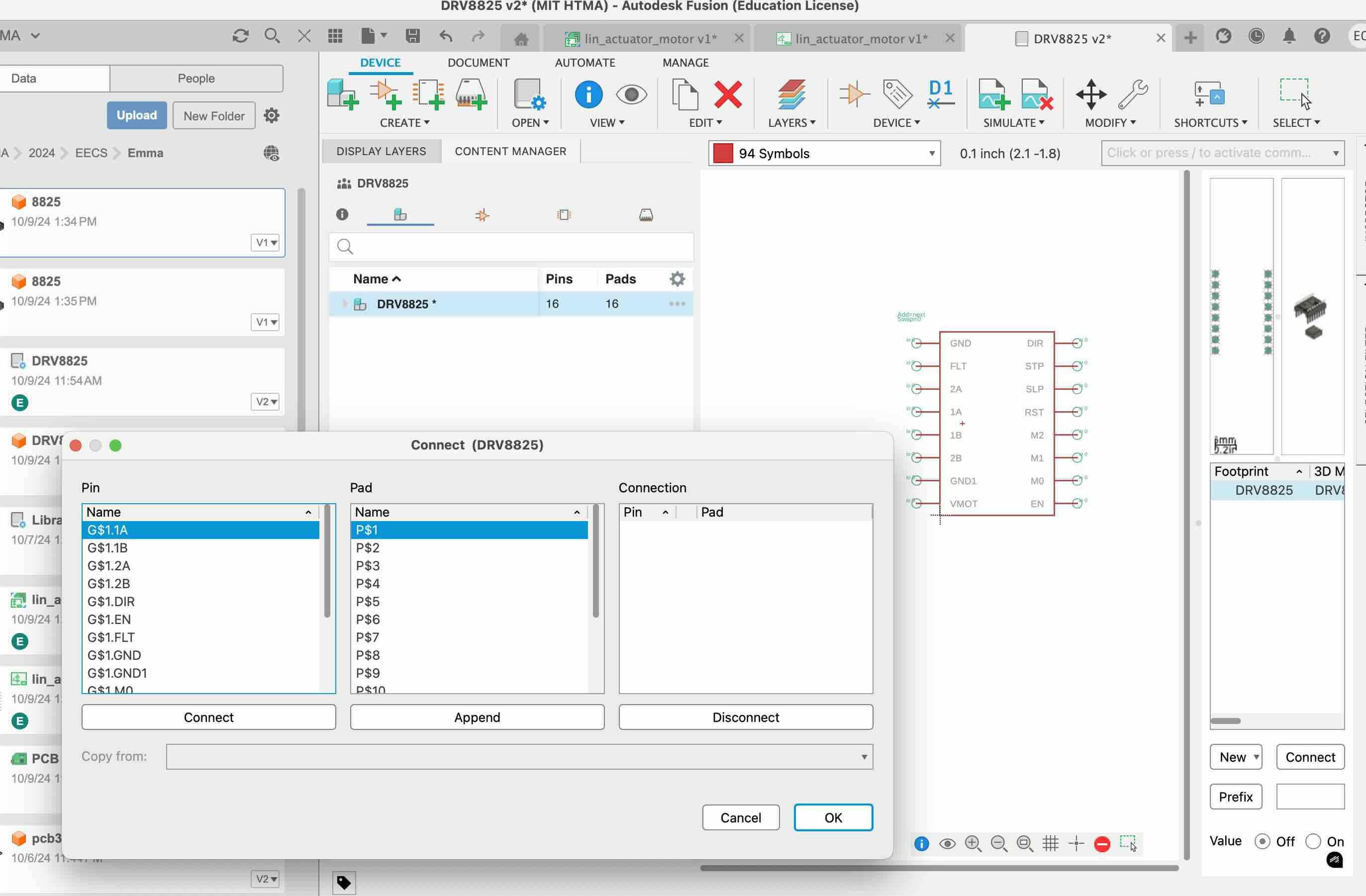
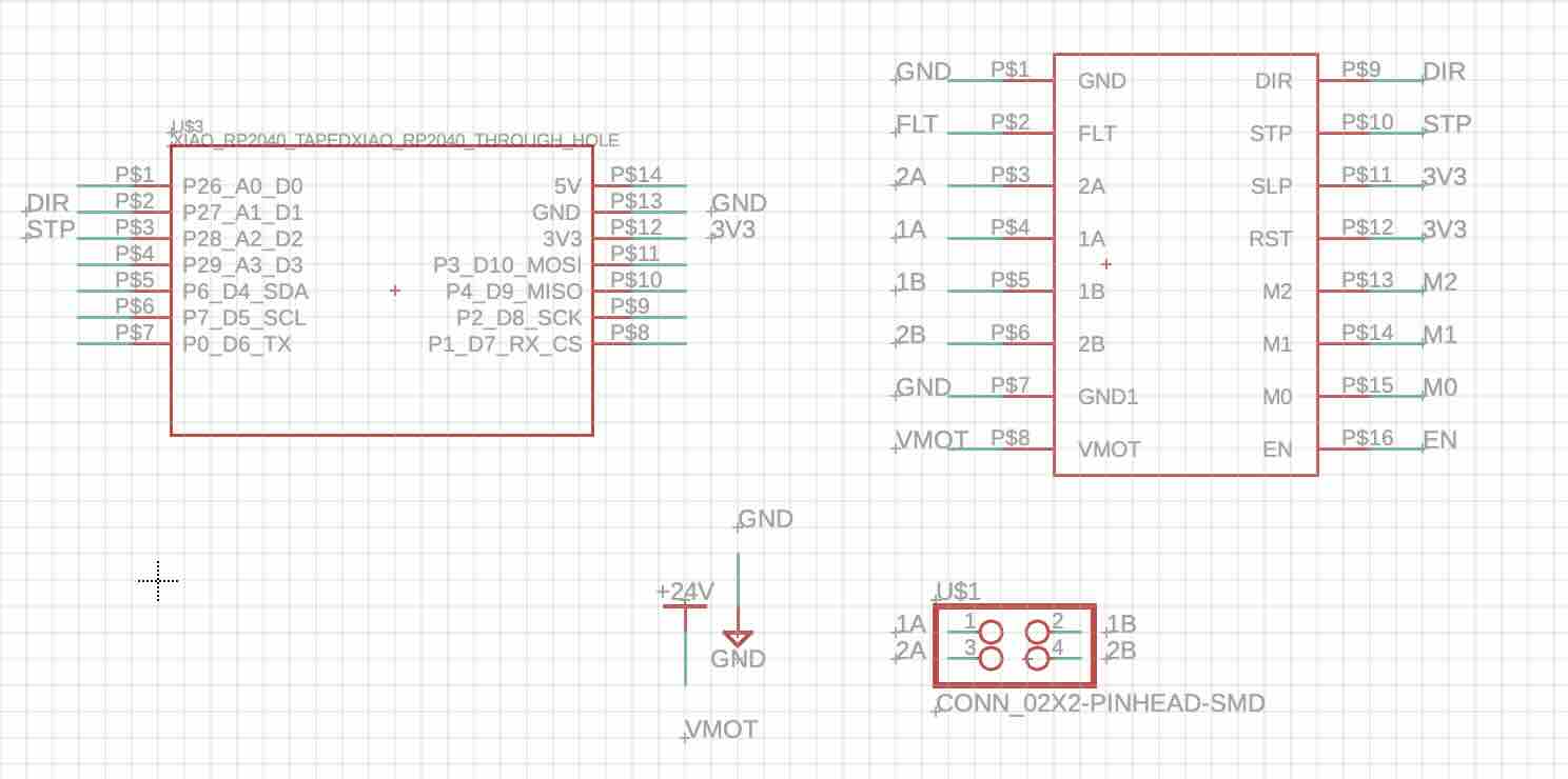
I learned from Marcello and Anthony about how to wire a driver and stepper motor to control my linear actuator. However, I had trouble finding a driver component - and the new part that I added to the library would not show properly for import into schematic.
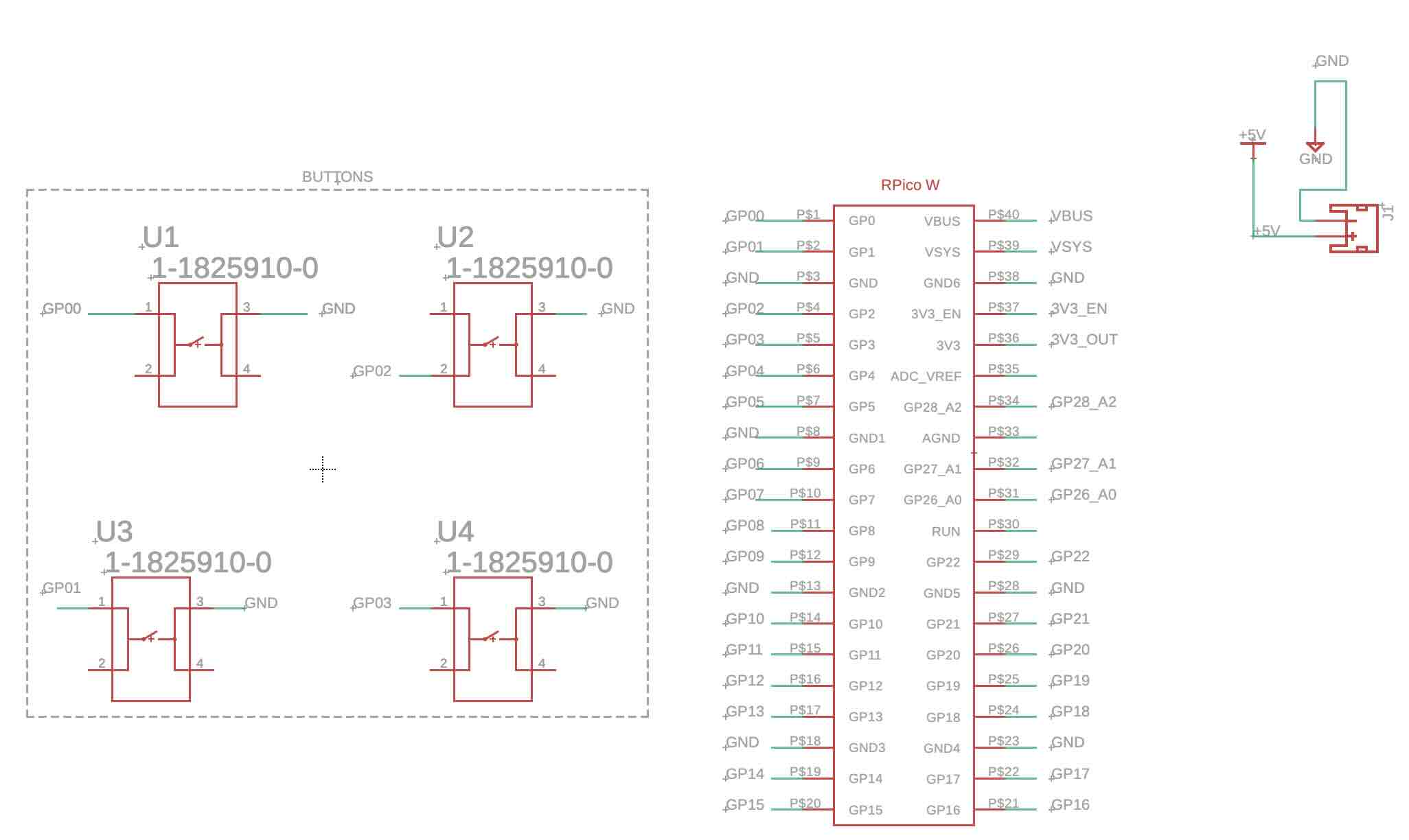
Week 6: Electronics Production
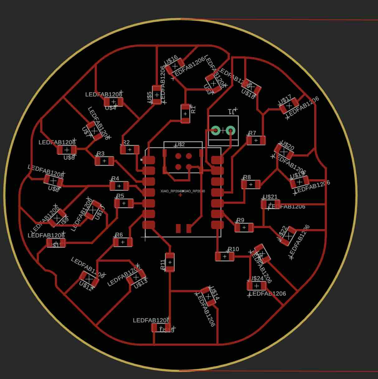
Find the PCB files here
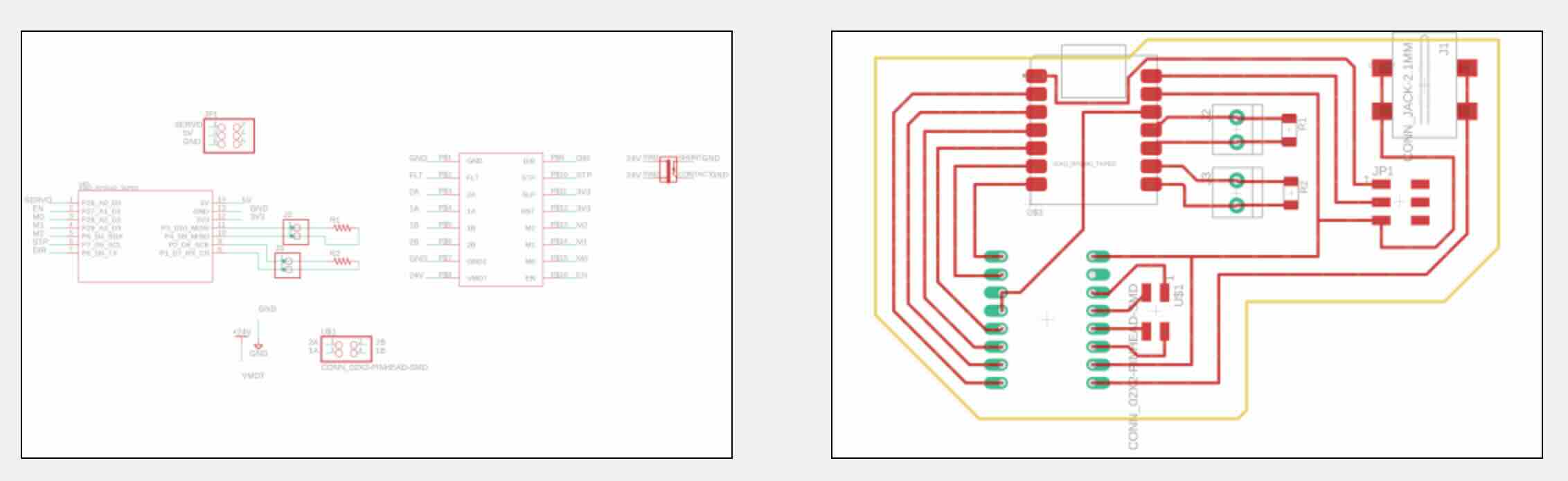
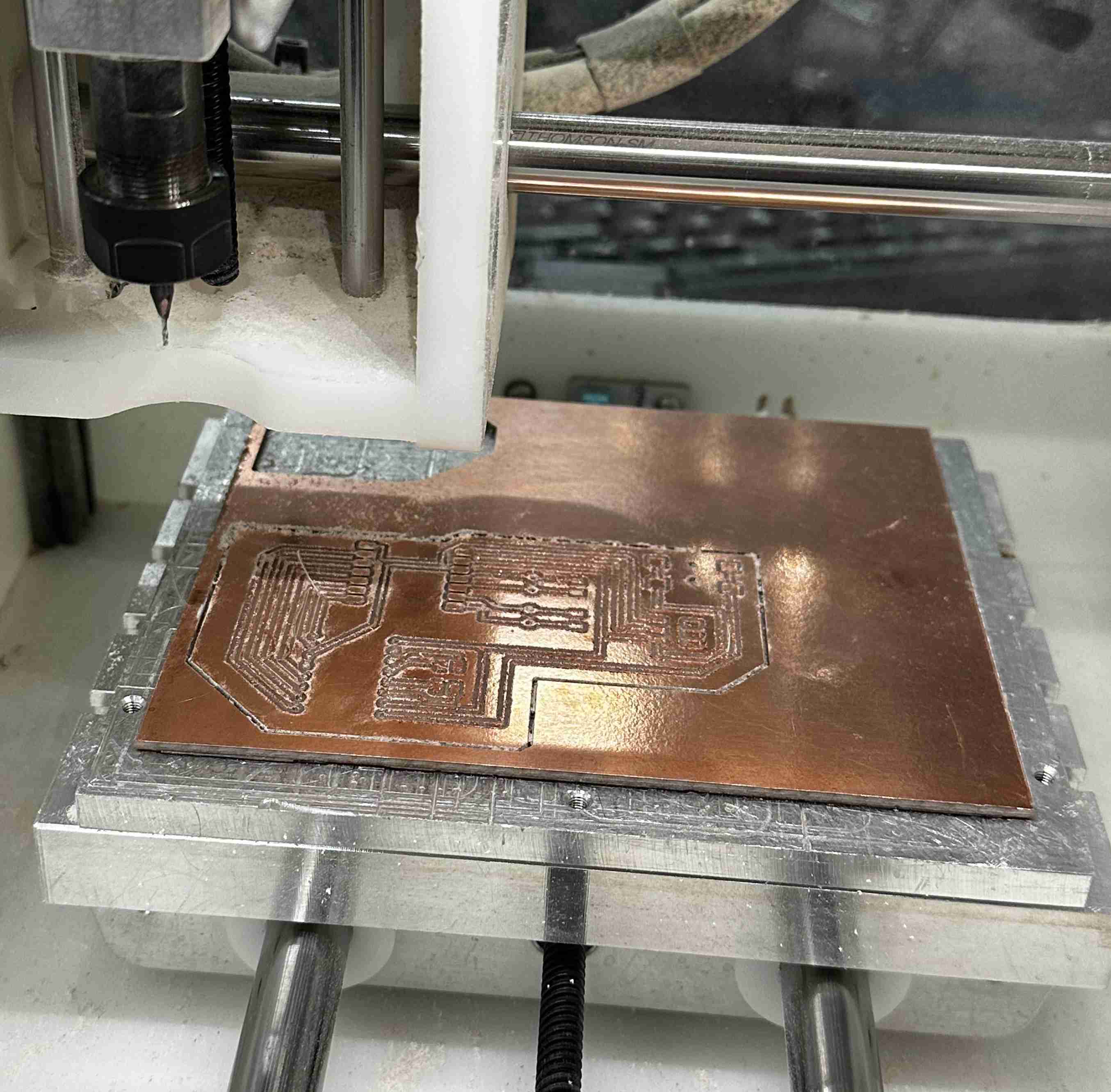
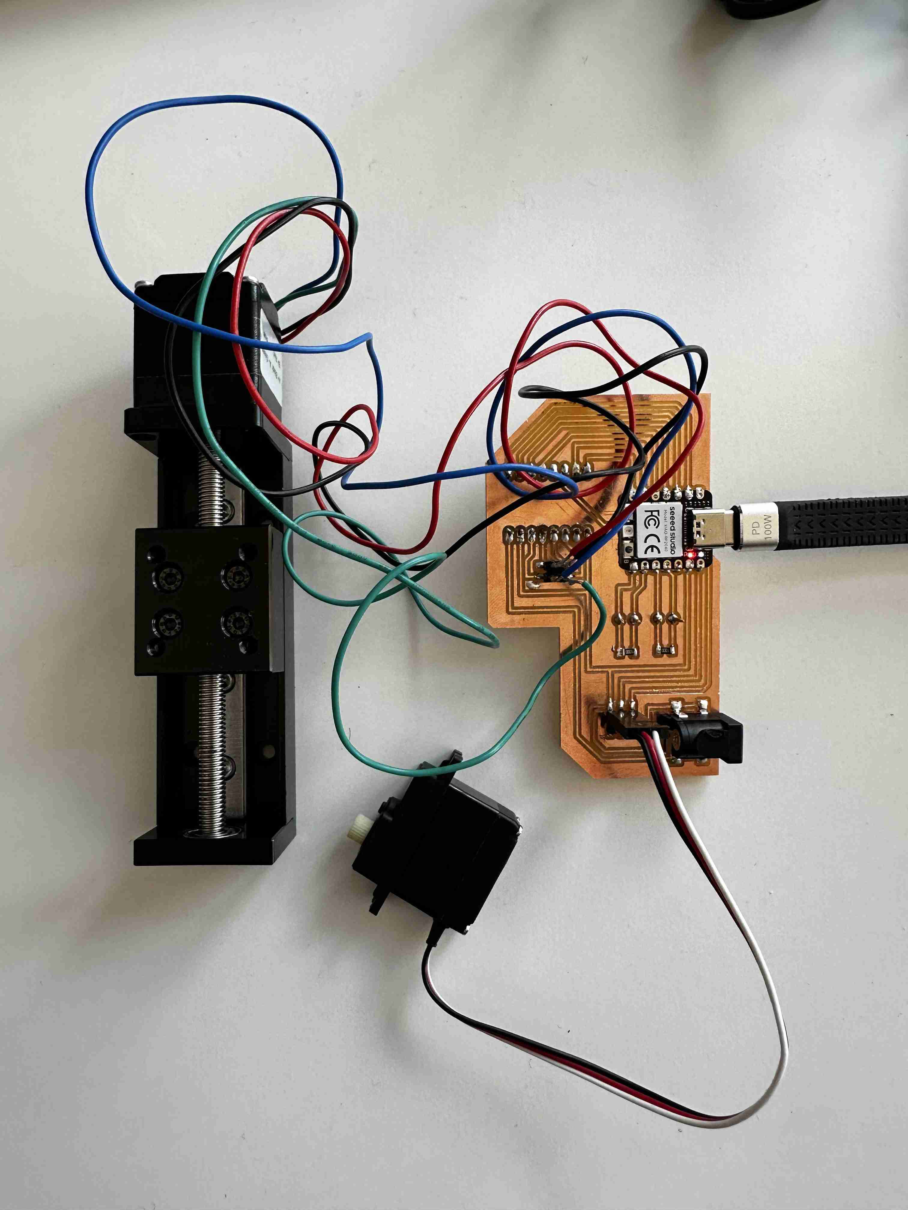
I soldered a xiao rp2040, a driver, pins for capacitance sensing, a linear actuator, and a servo motor.
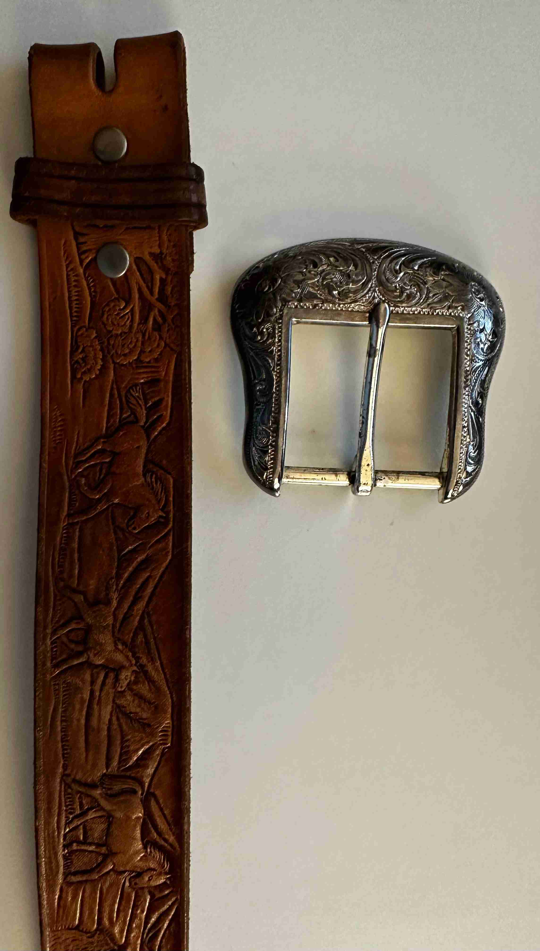
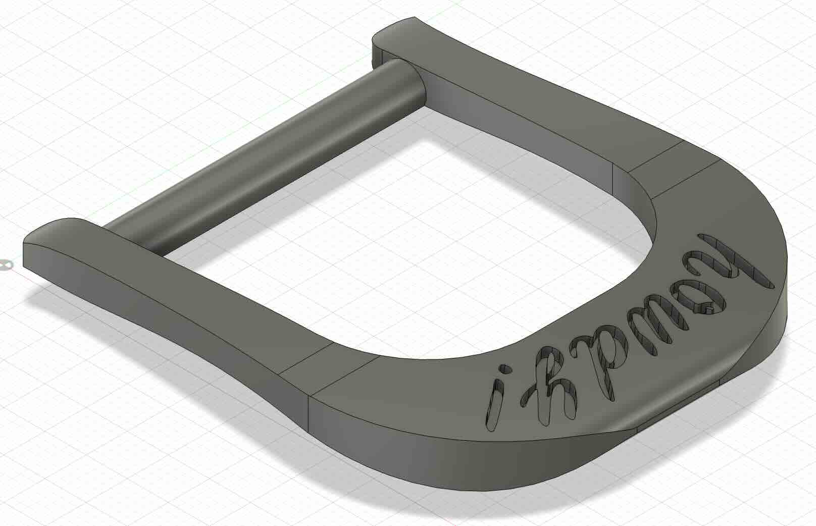
Week 7: Molding and Casting
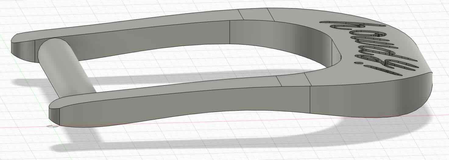
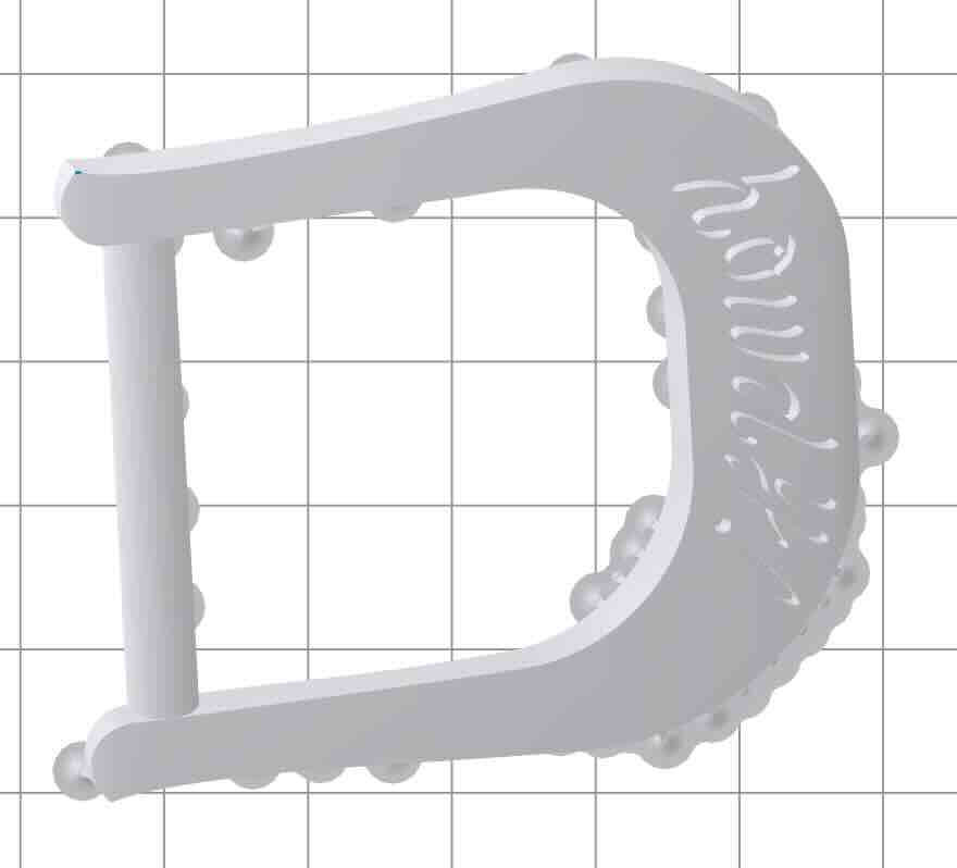
This week I wanted to replace a belt buckle that I hate.
Week 8: Input Devices
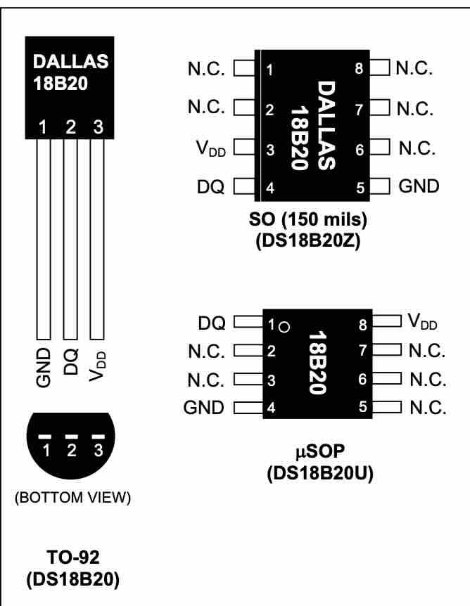
This week I wanted to add a temperature sensor to my mouse behavior rig. I expected that we would have a traditional thermistor in lab, but instead we just have a one-wire thermistor thing (DS18B20 TO-92). Datasheet here. The component seems to have been designed in Dallas (by dallas semiconductor) which is where I am from!
I connected the correct pins to ground, power and digital for data. I added a 4.7kOhm resistor between data and power pins. I uploaded this code to my arduino:
Week 9: Output Devices
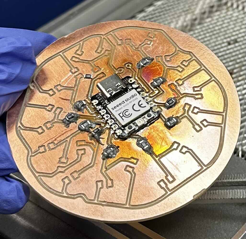
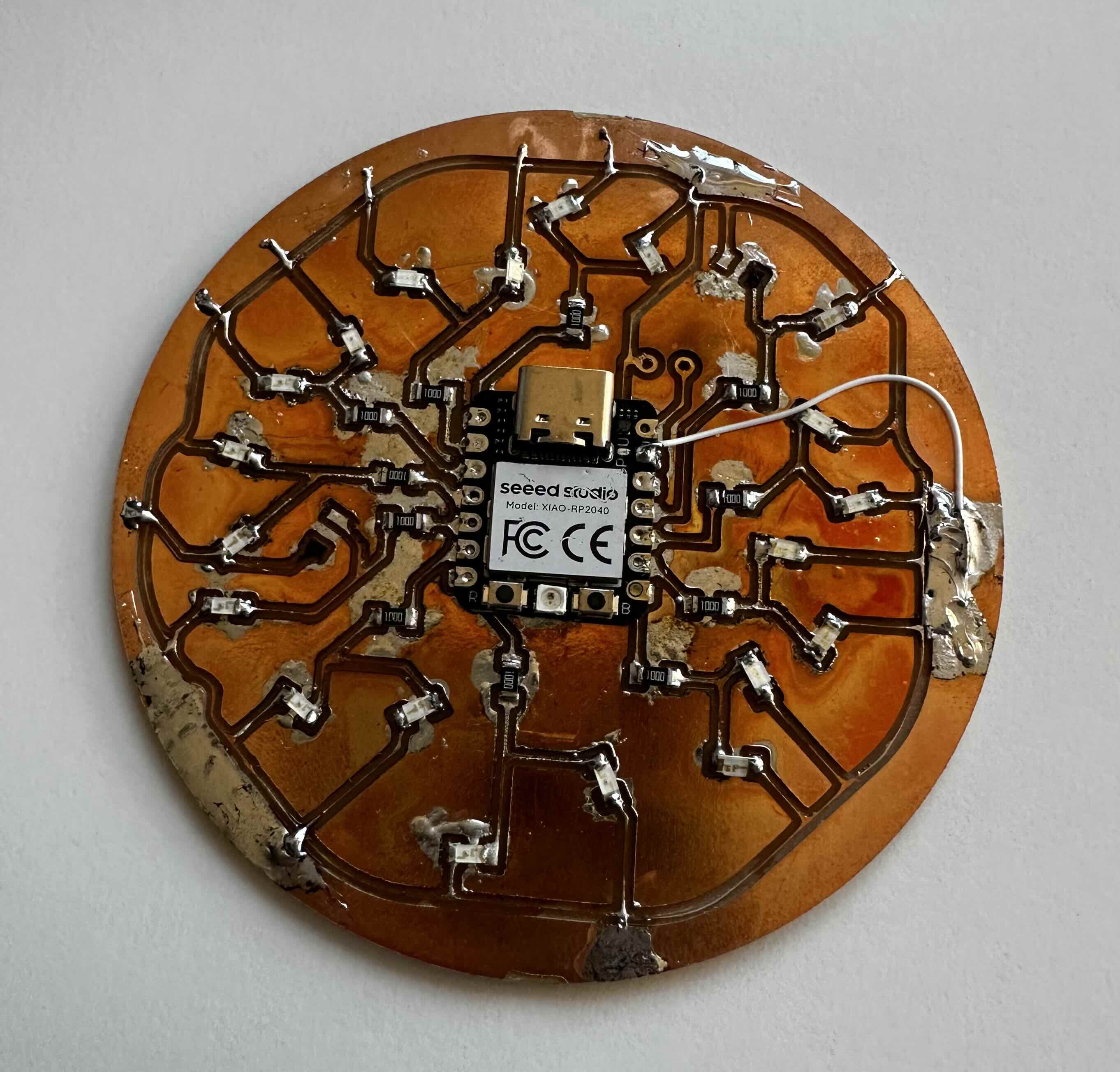
This week I made an ornament and tested out the solder paste with hot air method. I learned that I really perfer manual soldering, but I do think the hot air method allows you to scale your projects if done well. I also used the multimeter diode and connectivity testing extensively on this board after some thin traces ripped.
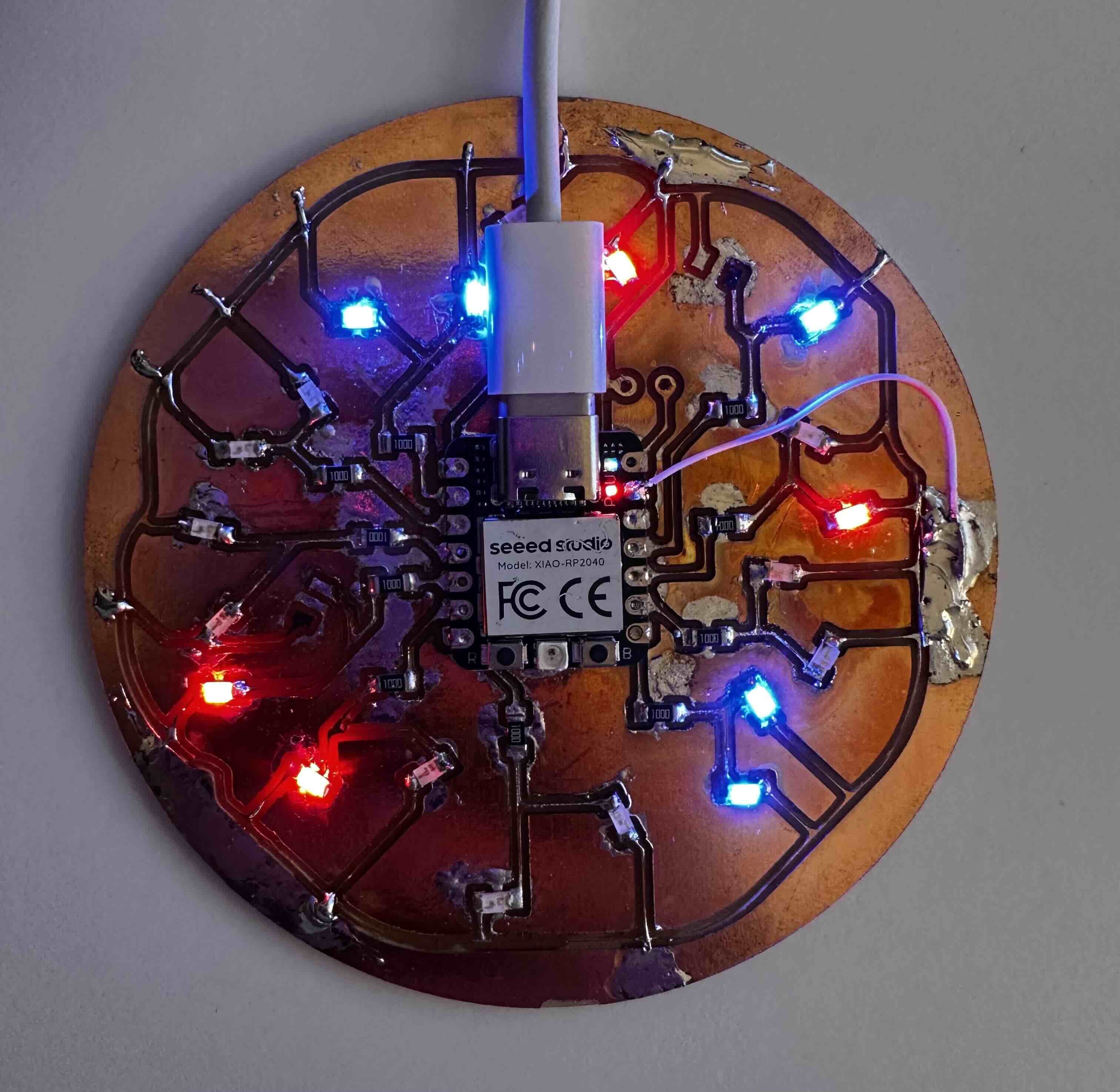
See ornament blinking here
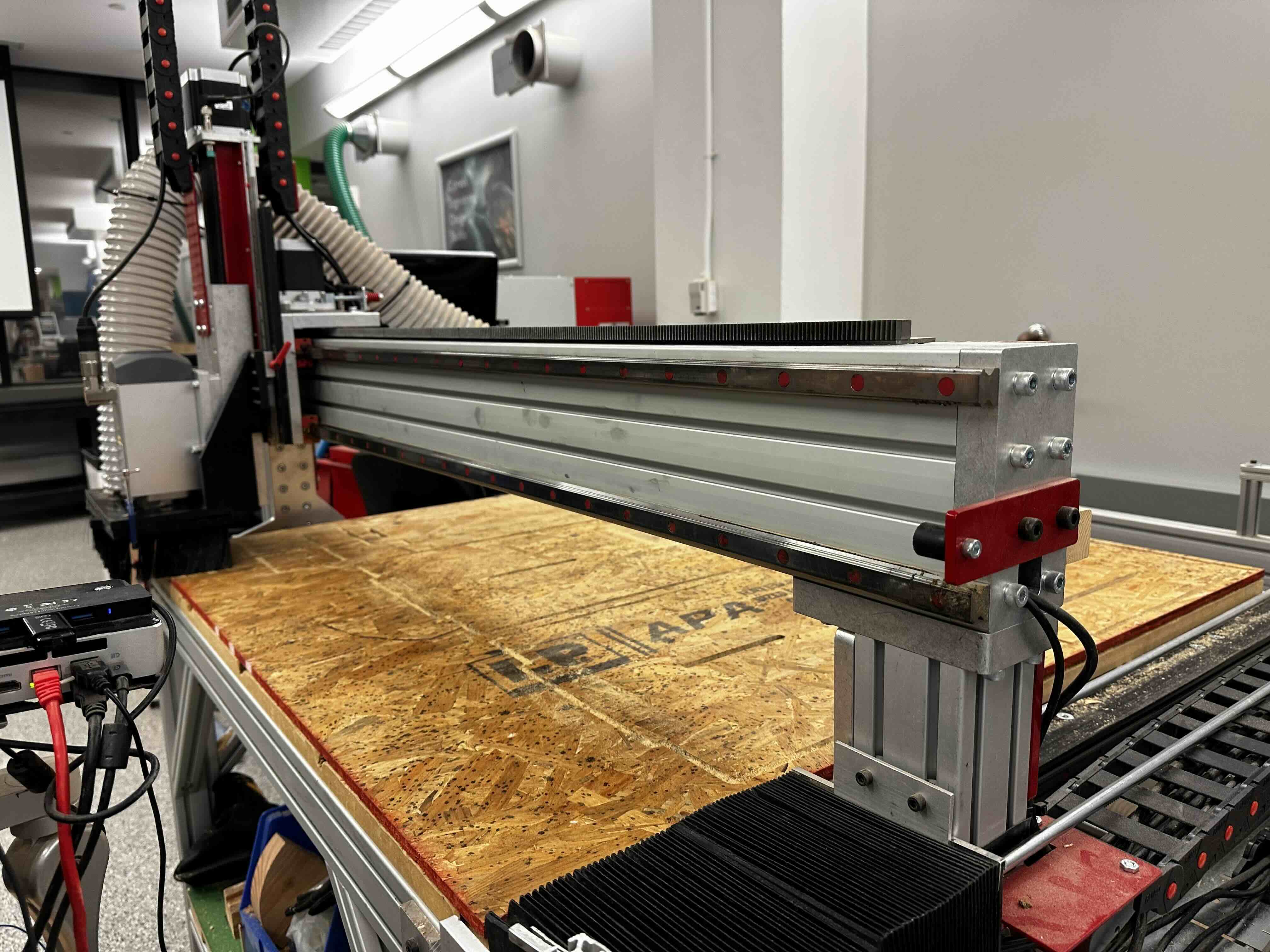
Week 10: Make Something Big
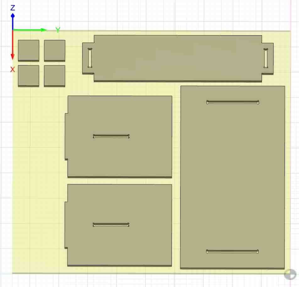
This week I made a simple bench with press-fit and wedge joints.
I prepared the CAD and Anthony walked me through the generation of g-code. It was important to add tabs to prevent the full release of parts from the board when CNC is operating, the tool rotates up to 15,000 rpm which can really send things flying!
Here is the shopbot cnc: