

This week's group assignment was super straightforward. Erik gave us a demo of testing a sensor (he was using a magnetometer) using an oscilliscope and saleae logic analyzer + software.
Last week I explored making laser-induced graphene flex sensors as an option for my final project. In class, I was selected to present my work for last week and when I showed my lig sensors and explained my project goal a bit, Neil told me to try step response and linked me here. Don't get me wrong, those sensors look awesome, but it's more complex than I need and the info in that paper isn't quite enough for me to feel confident about figuring out how to replicate it in this little time and with limited materials... I spent a while looking into this and trying to find similar things to try but I couldn't find anything too promising.
I've tried other types of bend/flex sensors in the past- in the DIY category, there's the resistive (velostat and copper tape) method ( something like this). For professionally manufactured ones, I've tried a few like this one from adafruit. I don't like the latter for this because the cost adds up when you need a lot of them, and they're non customizable and not the most durable over time. As for the DIY method shown above, it works fine but it's also not the sturdiest. I've also looked into this a LOT in the past for what it's worth so I feel like I have a good sense of the options... And no I am personally opposed to doing any of the resistive thread/ yarn/ fabric methods so do not ask. I've thought a lot (a lot) about how to possibly use hall sensors for this but I just can't come up with a way that I think will make it work reliably because they are so alignment sensitive. This incredibly cool final project by Francesca Perona utilized hall sensor hinges to detect folding-- I thought about trying something similar but there are 3 potential issues: the alignment needs to be consistent, there will likely be interference from adjacent fingers, and (less an issue but more a design change which would impact the tactile experience) I'd have to switch the sensors to be under the finger. I've managed to find a few examples of hall effect based sensor gloves but there isn't a lot out there. I may experiment with it just to see. Aside from all of that, I also looked at other examples of flex sensors people have made in the archive and there wasn't anything I could find that used a different method than the things listed above.
With all of that in mind, I think my goal for the week is to test hall effect sensors and experiment with lig to see if I can get something with a wider resistance range.
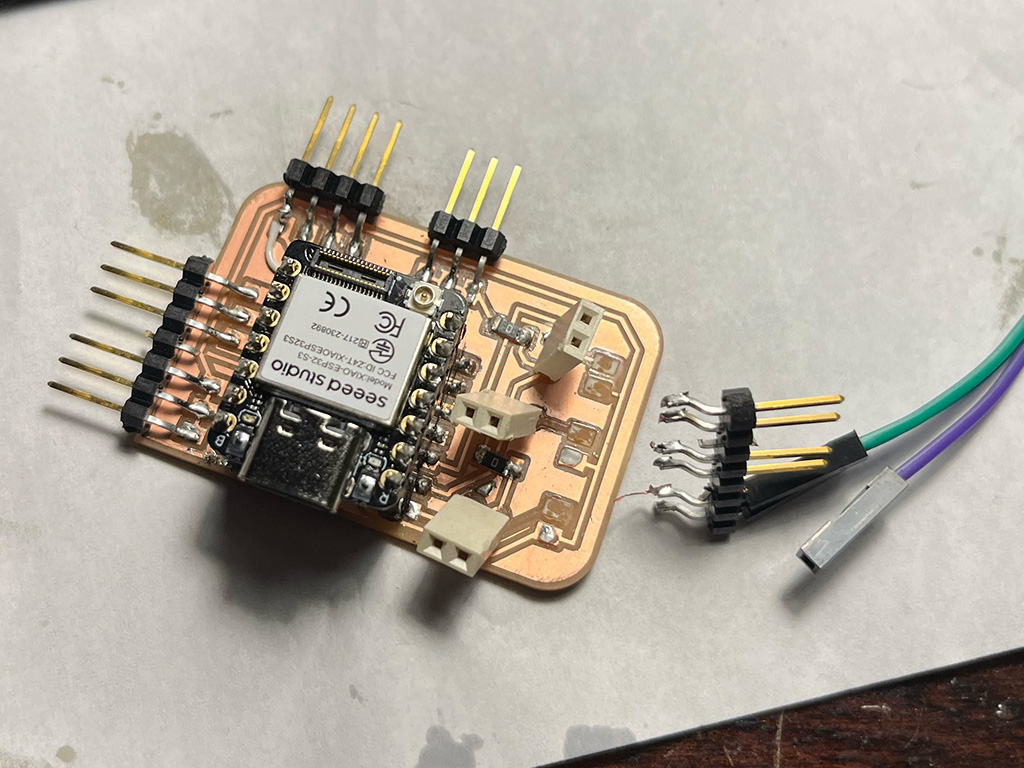
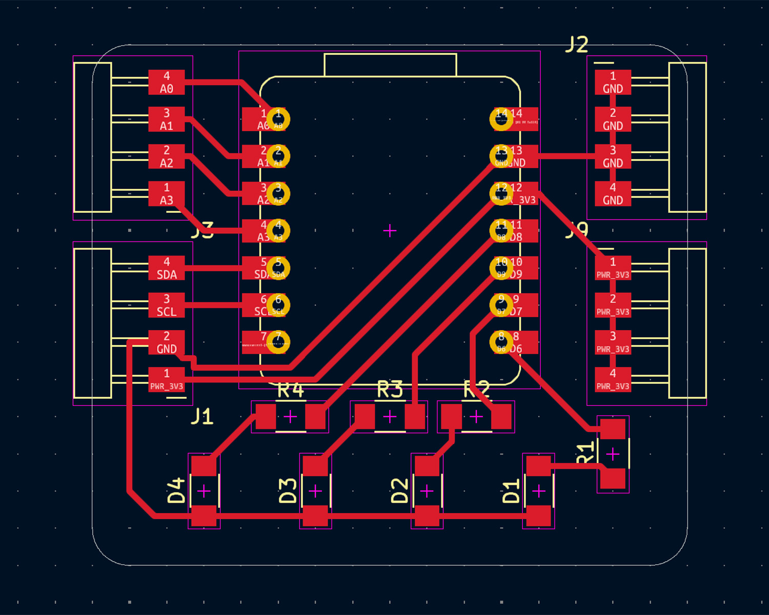
I wanted to update my board from a few weeks ago to make something which was better suited for this week (in that I could use it for hall sensors or flex sensors as analog inputs and I could easily change out the resistor value in the voltage divider circuit to suit different sensors). So I made a new board! Some things did not come out as expected but I worked it out through some hacky problem solving. (Yes, I am aware of the accidental trace which leads nowhere that I forgot to delete. It's fine, don't worry about it.)
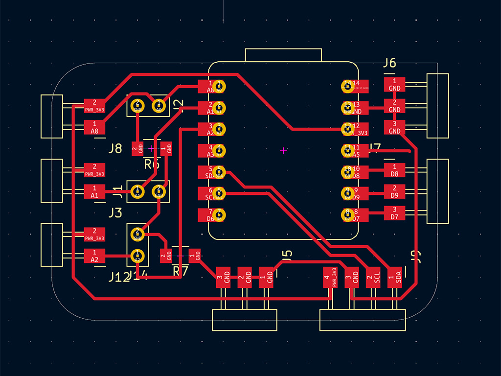
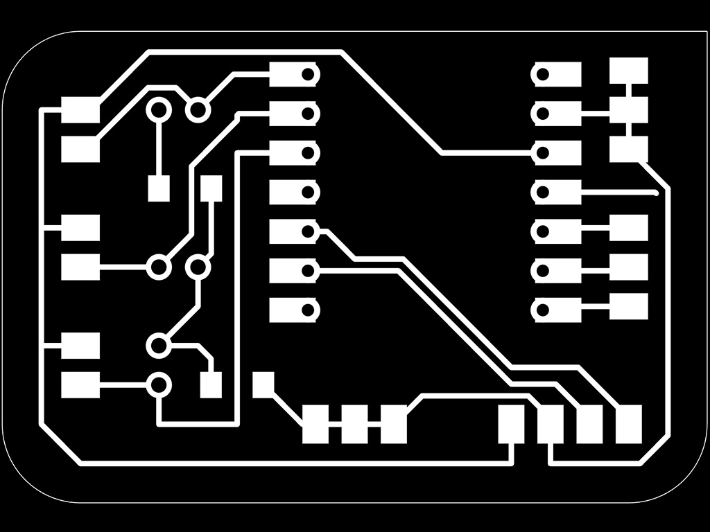
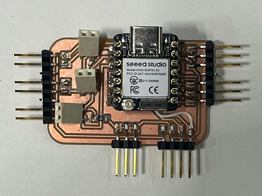
And then I tried to plug something in the next day and ripped a bunch of pins off!
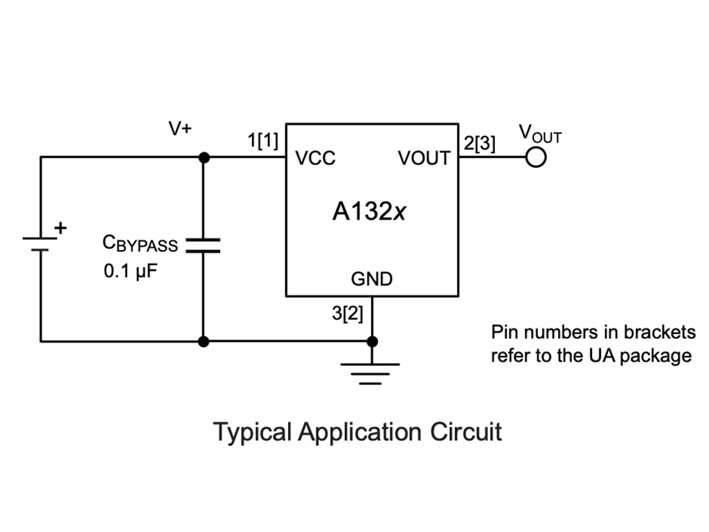
In the electronics room, I found some A1324 surface mount linear hall sensors (datasheet) and realized I would need to make breakouts to solder them to to be able to use them. I recreated this schematic (which incorporated a 100nf bypass capacitor) from the datasheet in kicad:
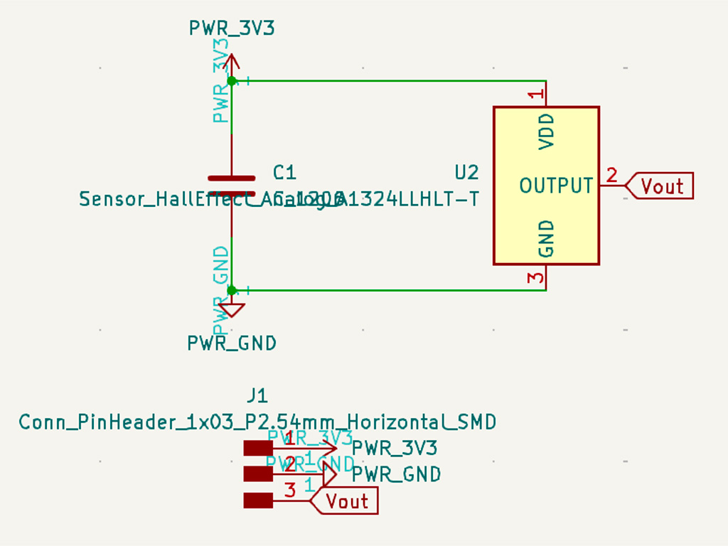
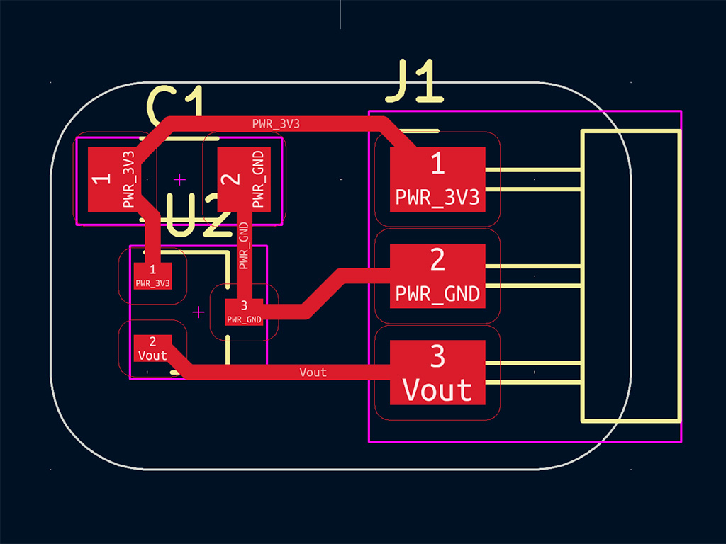
Then I made a simple little PCB with all pins in a row on one side for easy plugging in for testing. I milled a handful of them (which was helpful because I broke a couple trying to snap them off of the larger board). Soldering them was really tough because they are so tiny!

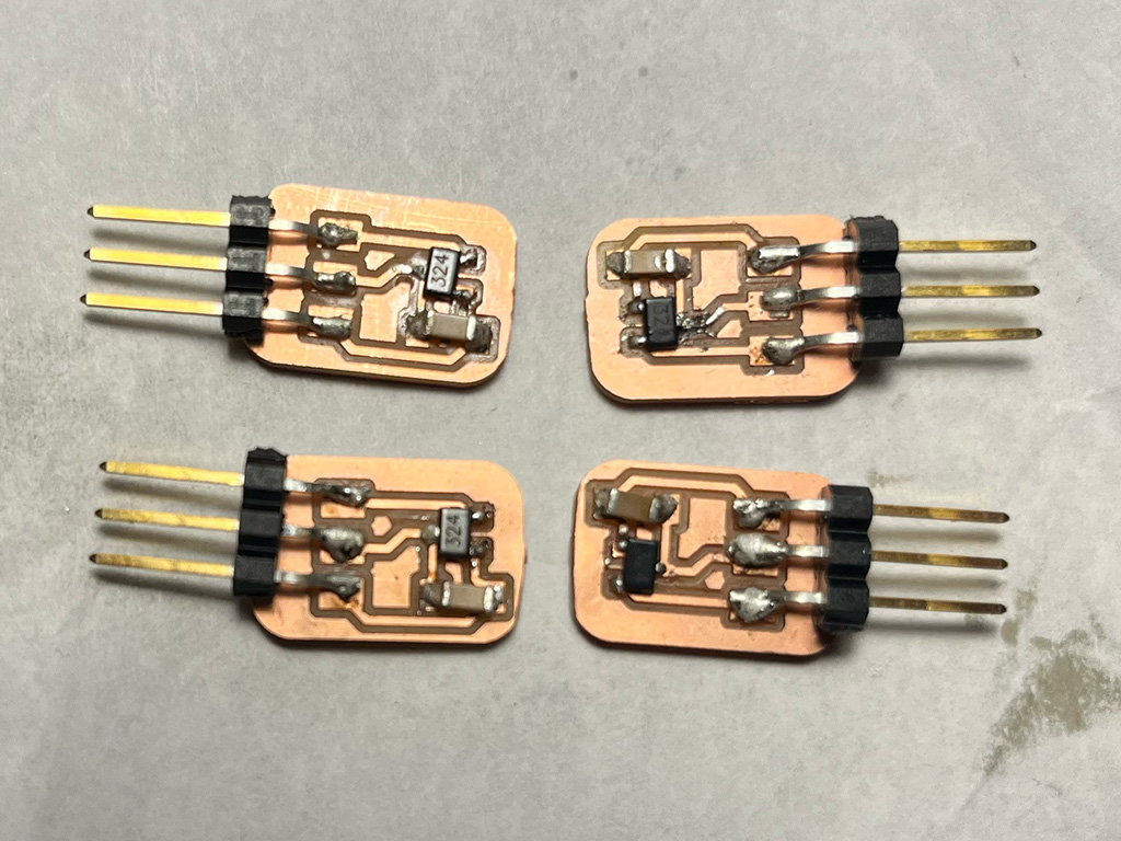
Since I broke my last board, I decided to test a sensor by plugging directly into the ESP32 and the results looked really promising so I decided to mill yet another board so I could test multiple at once.
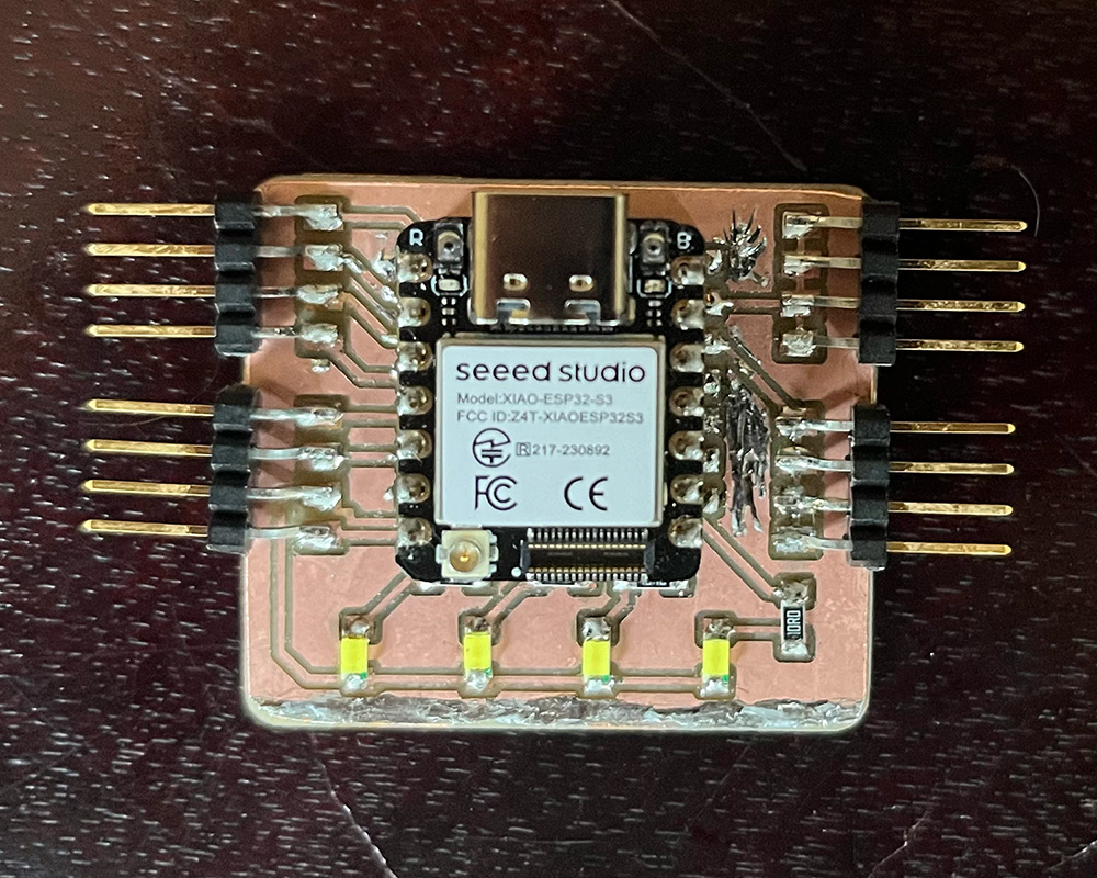
For this design I went as simple as possible: Sets of 4 analog, GND, and 3v3 pins for hall sensors, GND, 3v3, SDA, SCL pins for the IMU, and sets of 4 GPIO and GND pins for LEDs. And then after some consideration I redid the design to have the LEDs built into the board because for simple testing that is going to make my life WAY easier. This board turned out great and I superglued the pins on this time because I have ripped off too many pins to make that mistake again... And the stray solder mess is me turning my mistakes into decoration
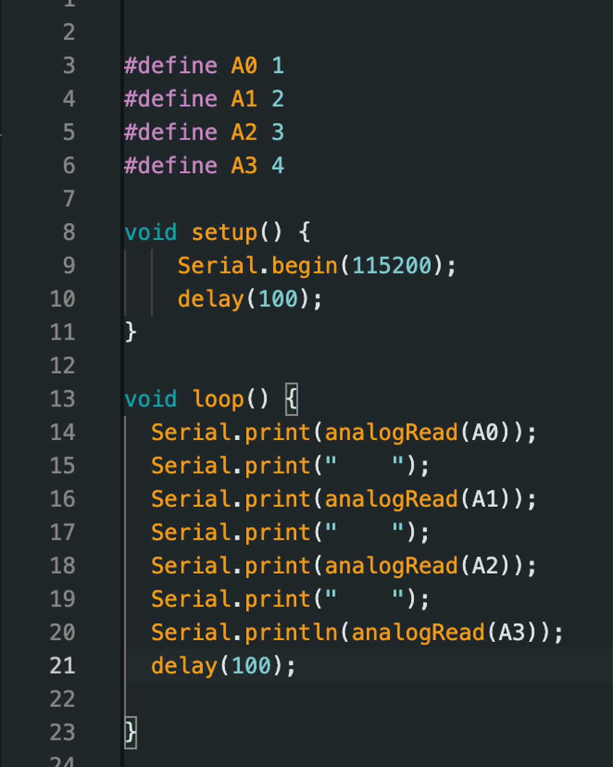
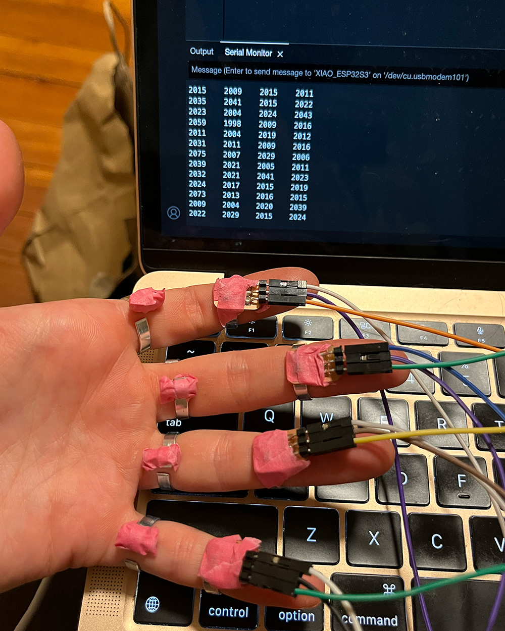
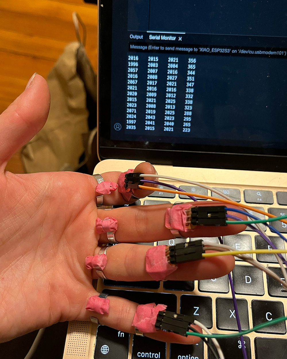
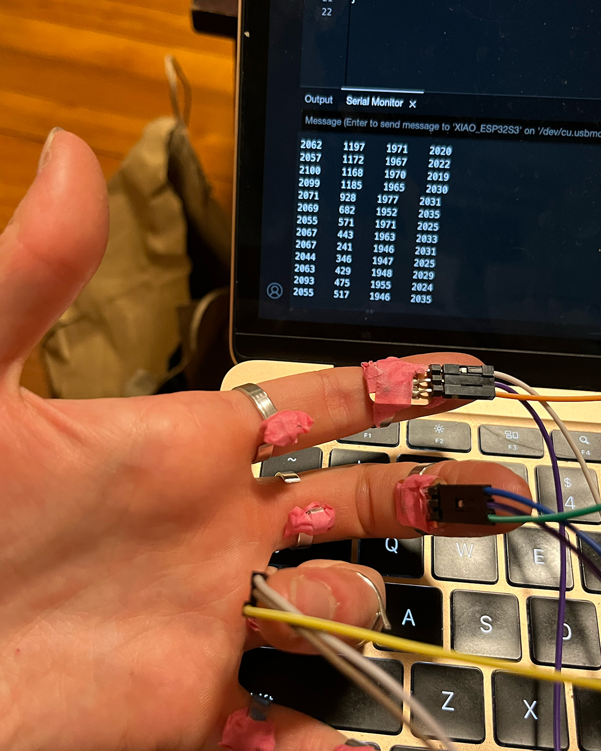
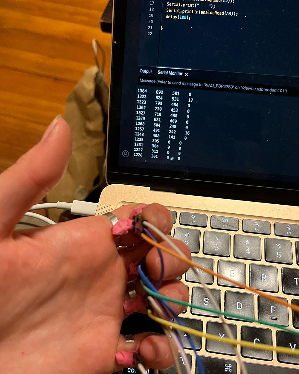
I made some rings with flat aluminum wire to hold the hall sensors and magnets and wrote simple code to read the analog inputs:
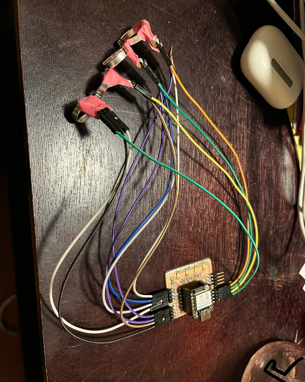
These photos show the sensors/their readings in action. I think this may work for my final project but it will require getting a good fit so that things don't slide around too much as that can really impact the reading.
Building off the LIG sensors I learned how to make last week, I decided to make more and try varying parameters to see if I could increase the resistance range. After talking to Wedyan, I settled on these designs I made in illustrator:
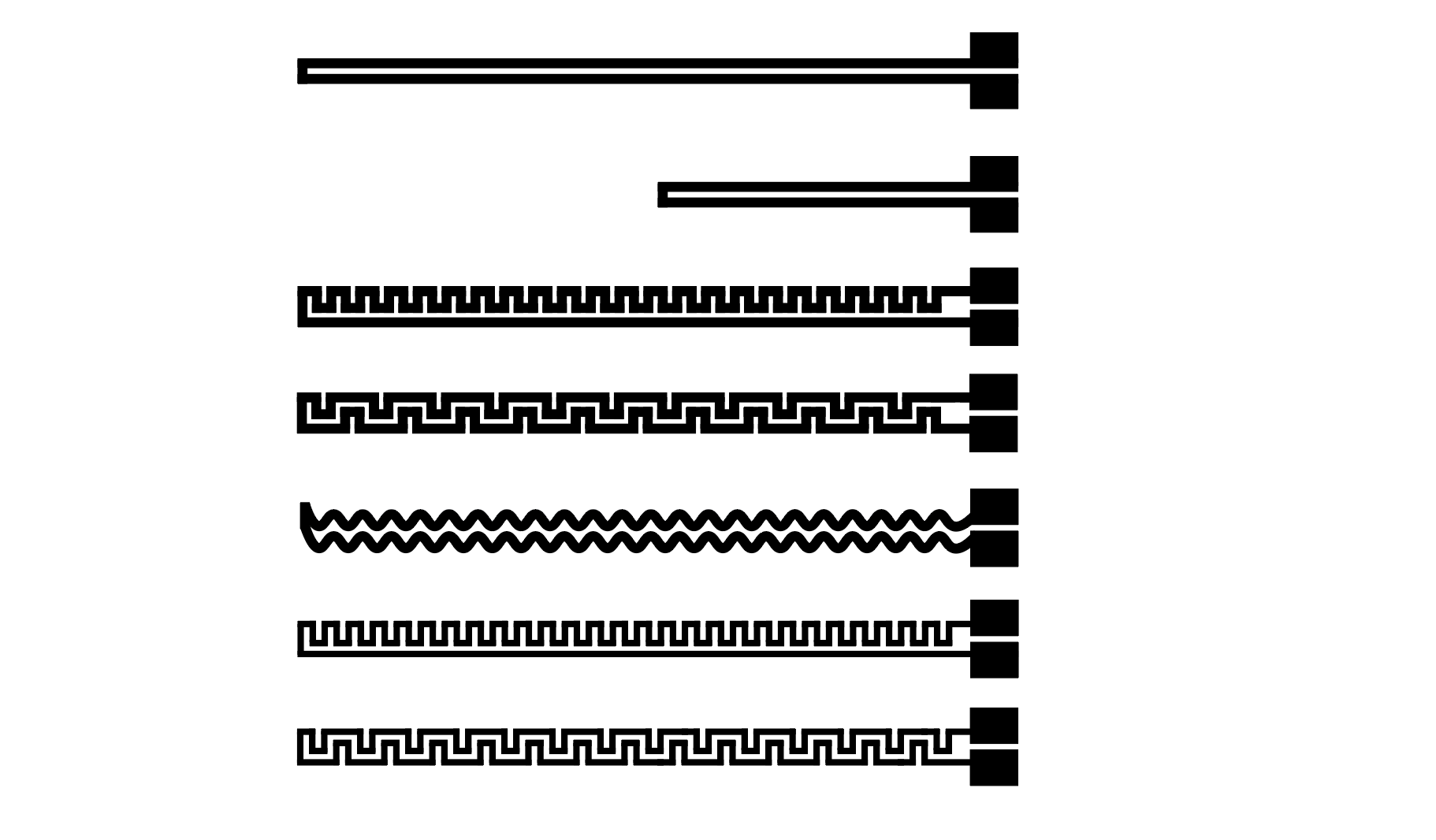
And then I made them! It was a bit stressful going through the process all by myself this time but it worked out well. I made one set with the power set to 8 and one set with the power set to 14 (marked with silver dots at the top). The 14 power ones were noticeably flakier and some lost a bit of graphene in the process but not enough that they didn't work. In fact-- all 14 sensors survived the process!
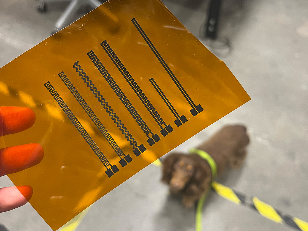
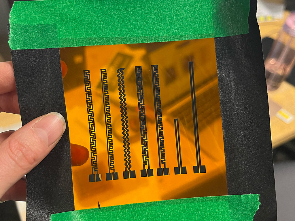
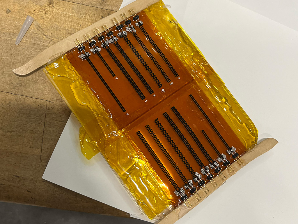
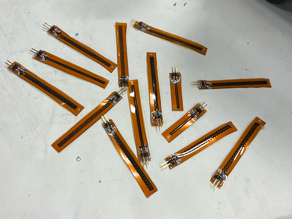
I then used a multimeter to test the baseline resistance and resistance range, comparing the designs and the power settings. The zipper-looking designs gave me the widest range, and the 0.5mm thick ones were better. The difference in power was inconclusive but I think this was influenced by my polyimide not being totally flat because I didn't remember to glue it down before putting it in the laser. Even the best performing sensor still had a resistance range (from straight to right angle bend roughly) of 0.8k ohms. According to wedyan, transfering the graphene so that both sides are coated in PDMS makes a big difference, so (if hall sensors don't work out) I will try that next.
Last but not least, I wanted to test out the BNO085 IMU sensor. I've used other IMUs before but this one seems to be much better in regards to outputting
really clean/easy to work with data! I've seen some things about it not working well with esp32 because it "violates the i2c protocol" (adafruit says this here)
but luckily I didn't seem to have any issue running it!
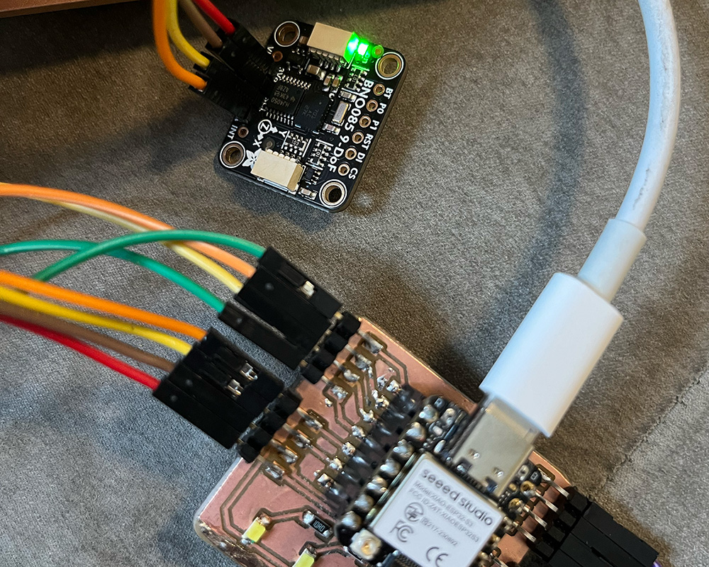
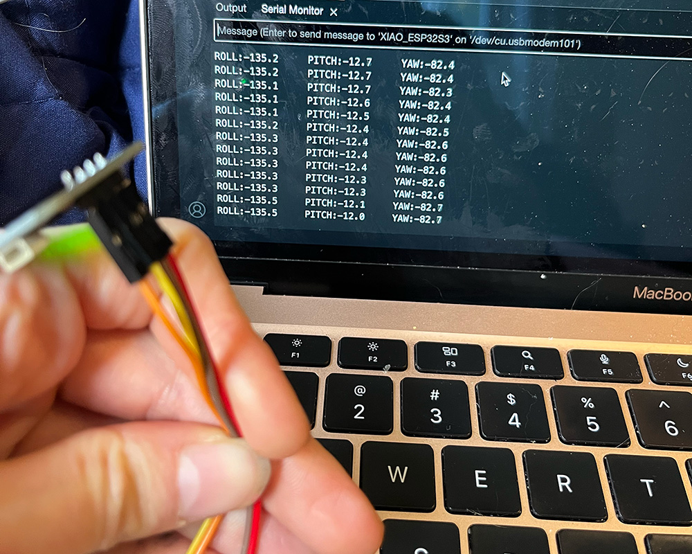
I connected the sensor to my board with jumper cables and tested out euler angle example code from the Sparkfun BNO08x Arduino Library and then modified that a bit to cut out unnecessary things and add labels. It worked so well! I am excited to be able to implement this in my final project.

-- Hall sensor pcb pngs
-- Hall sensor carvera file
-- Dev board pcb pngs
-- Dev board carvera file
-- Code for reading the hall sensors
-- SVG for the LIG sensor design
-- Code for testing the BNO085