Final Project
Wax-based propellant Research Demo

In Space Enabled, we are researching how wax can be used as a propellant in space. There's been mutiple experiments in parabolic flight and low earth orbit, and next year we will be sending another experiment to the ISS.
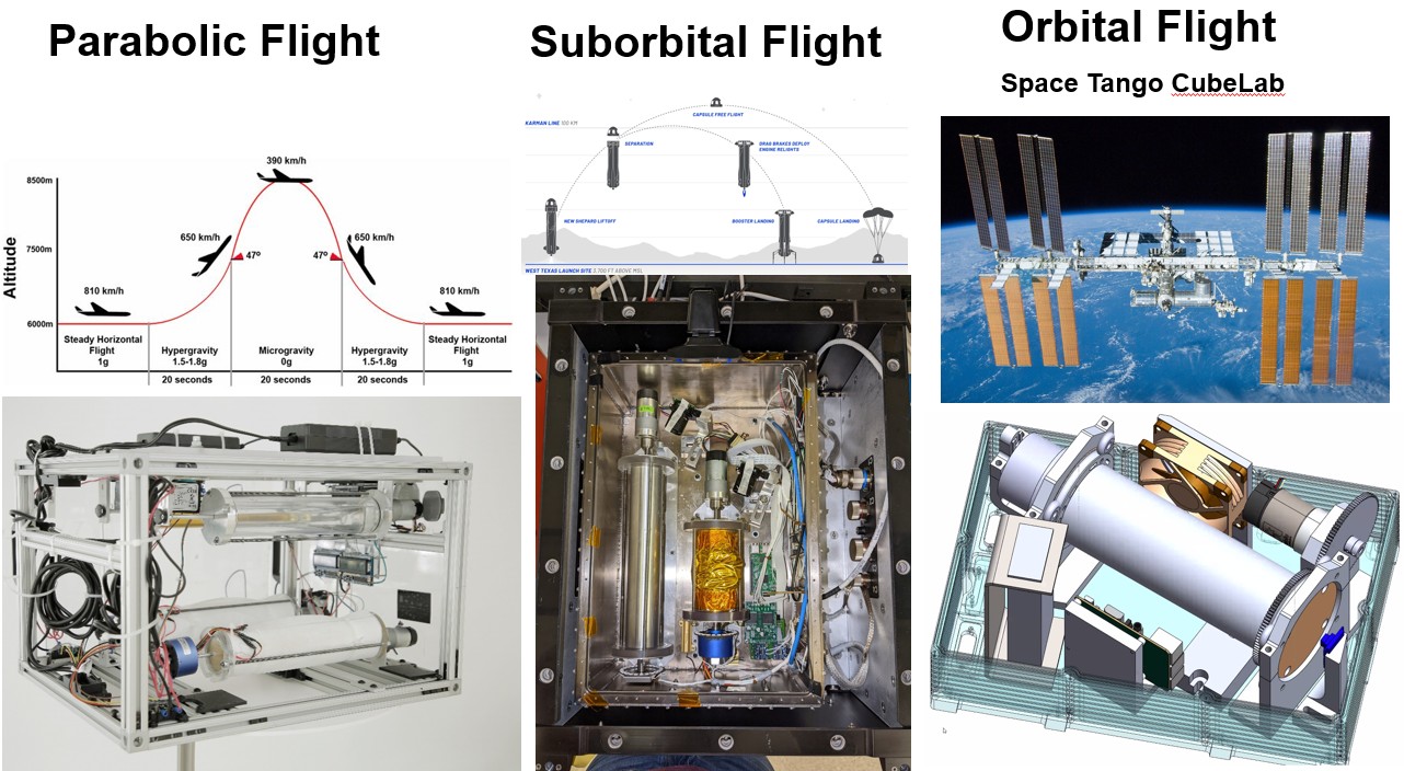
We're actively working on these cool models, but we only have the flight models. These are delicate and often in the facilities of our partners, so we don't actually have a physical demonstration in the lab. We've wanted to have a benchmark to test against or a model to make fixes in-house.
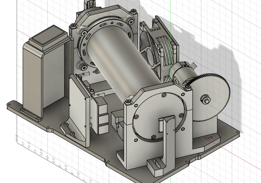
I will be using this class to create a desktop version that can be used to test different wax and have a local benchmark to be able to do experiments. In addition, this will be useful to explain and demonstrate the research to visitors.
Ideally, it will be able to run two separate cylinders to have a heated an unheated version.
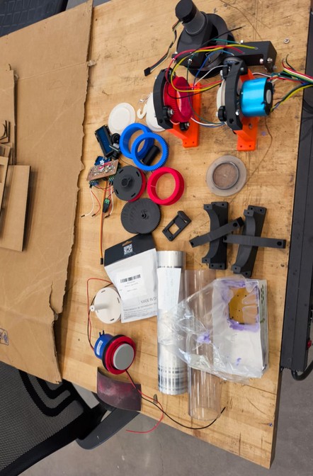
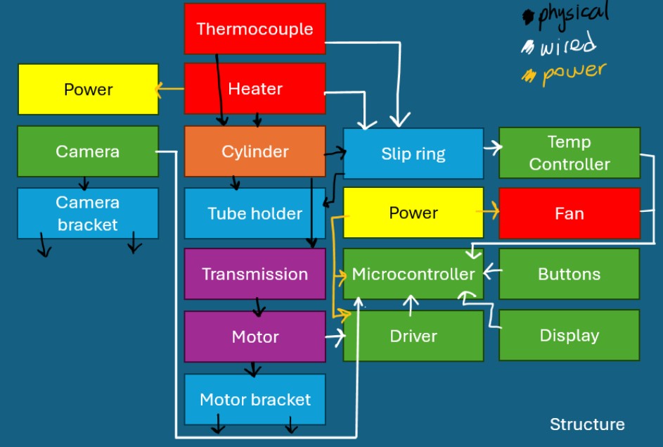
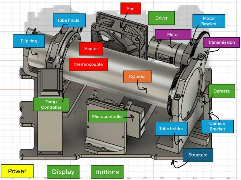
Parts:
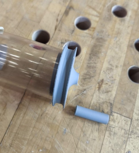
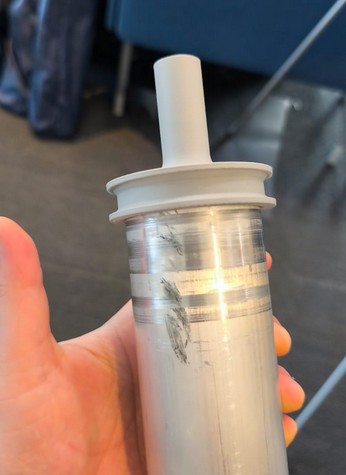
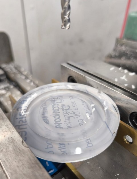
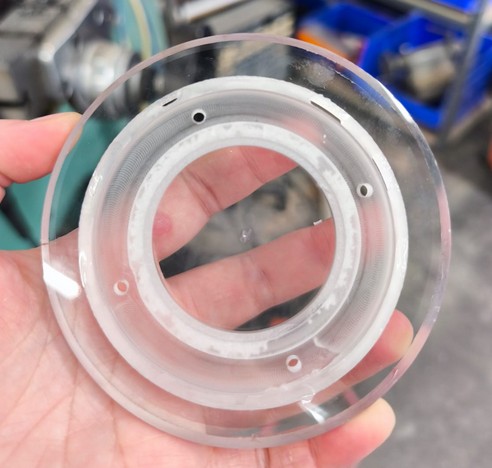
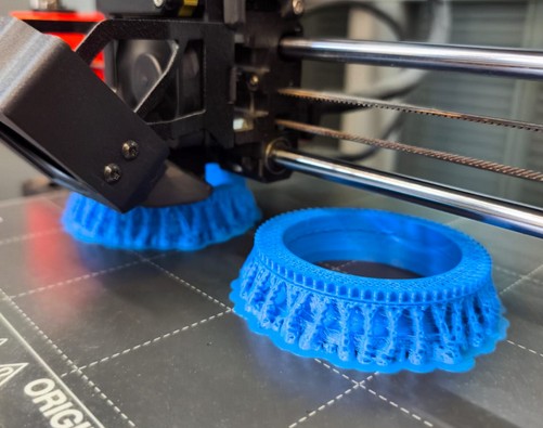
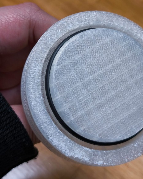
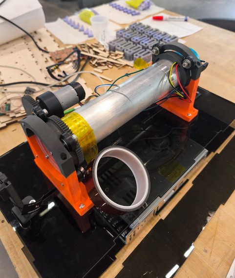
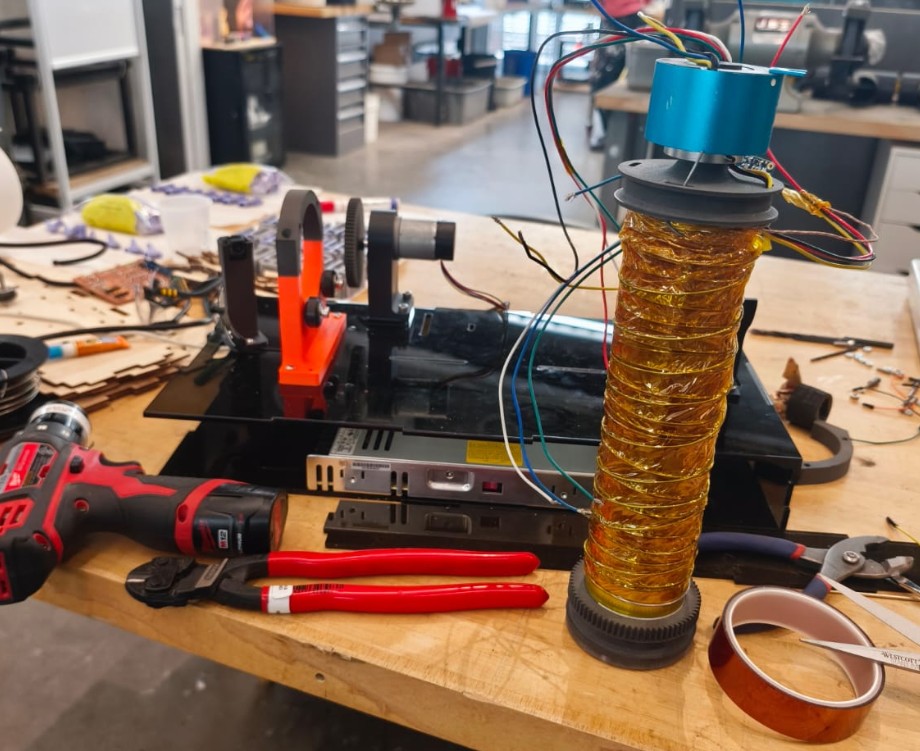
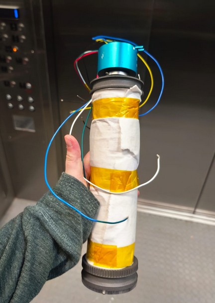
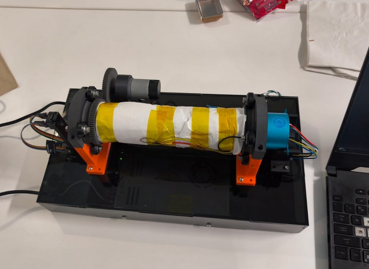
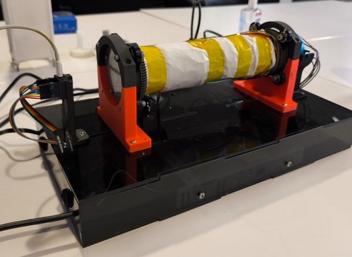
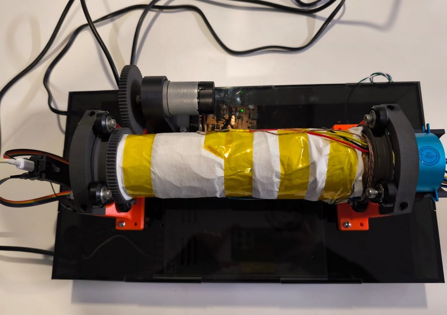
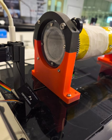
- Cilinder: Transparent polycarbonate cilinder that can hold at least 1kg of wax. Ideally, it can be interchanged easily (quick release) and adjust for other tube lengths. Even better, to have a valve system that allows to easily fill it up.
- Heater: Heating element controlled with a PID.
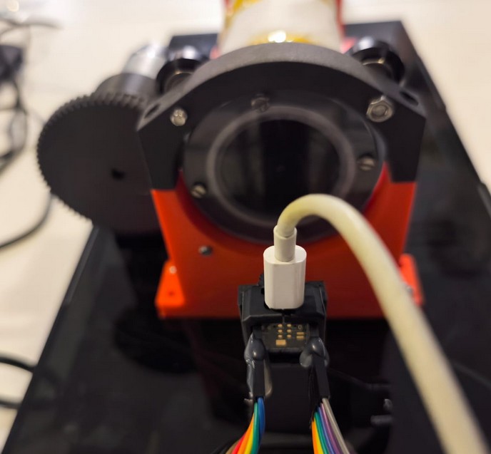
- Thermocouples: To read the temperature of the wax and do the feedback loop on the PID.
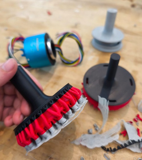
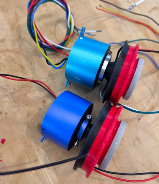
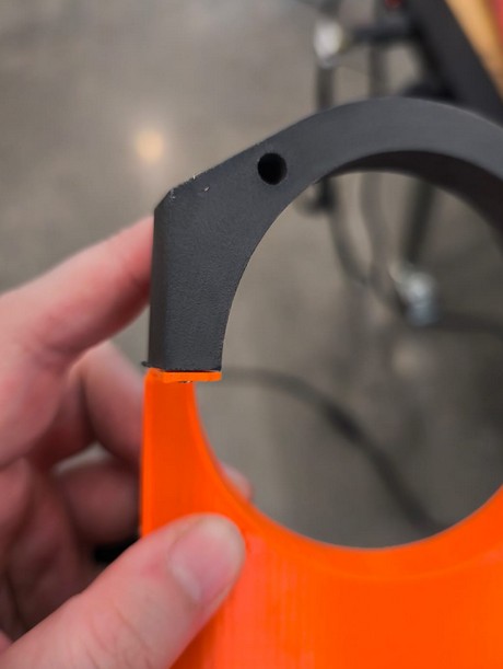
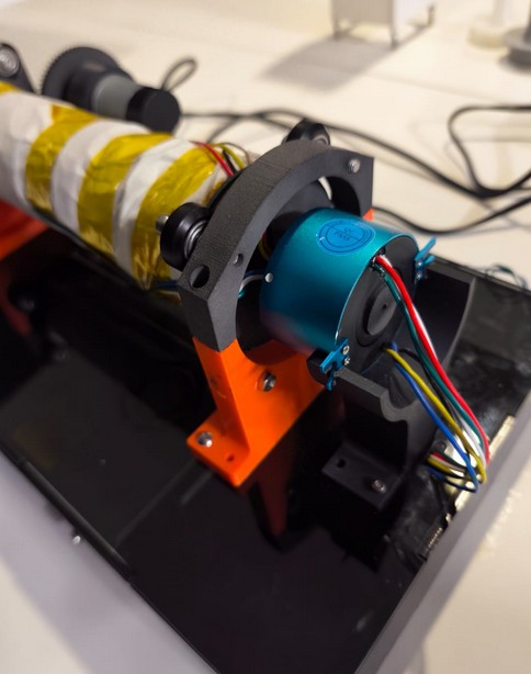
- Tubeholder: Allow free rotation of the cylinder. This requires a slip ring to allow for the rotation of the wires. Ideally adjustable for different lengths of tube.
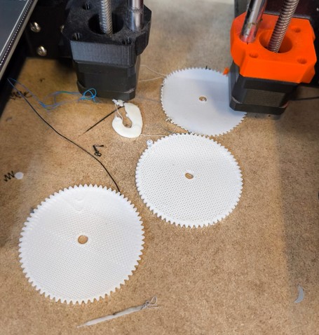
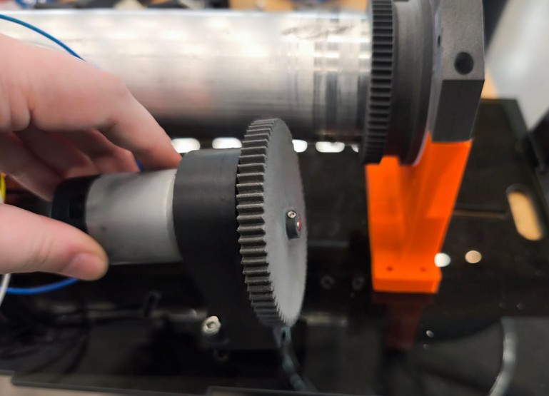
- Transmission: Gears to transmit the power from the motor.
- Motor braket: Adjustable to different gears and motor shafts
- Motor: DC motor with encoder/hall sensors for speed control
- Motor driver: Allow for speed/torque control and enconder/hall sensor
- Camera: to record the annulus formation
- Camera bracket: to position correctly, adjustable for different camera
- Microcontroller: to control display, camera, motor, heater and temperature sensors. Migh need a microcontroler separte for the cameras. Internet connection to allow for camera information and upload new programs.
- Display: to show current parameters for motor, heater, temperature, time stamp and possibly other information. Menu to change modes and select preexisting programns/ramps.
- Buttons: to control display
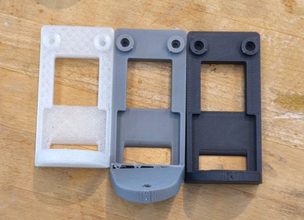
- Structure: Hold everything together. Able to mount to work table. Allows for certain amount of portability.
- Power source: to power everything
Here's the rough plan to achieve this over the next weeks:
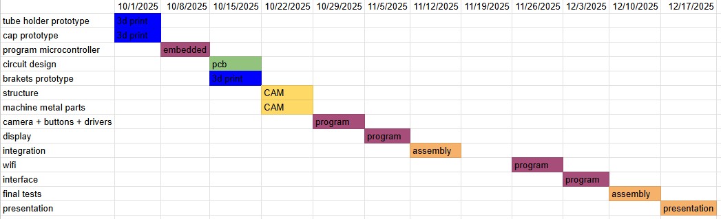
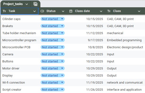
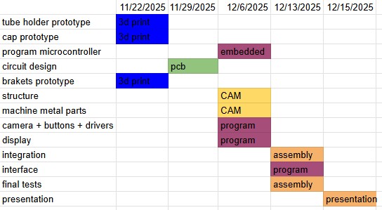
Big update: that calendar was not realistic. The weekly assignments did not all line up in the way I hoped for. One month before project is due, this is the real timeline:
Progress update:
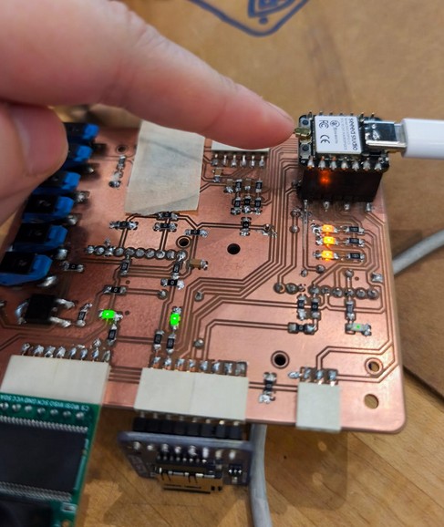
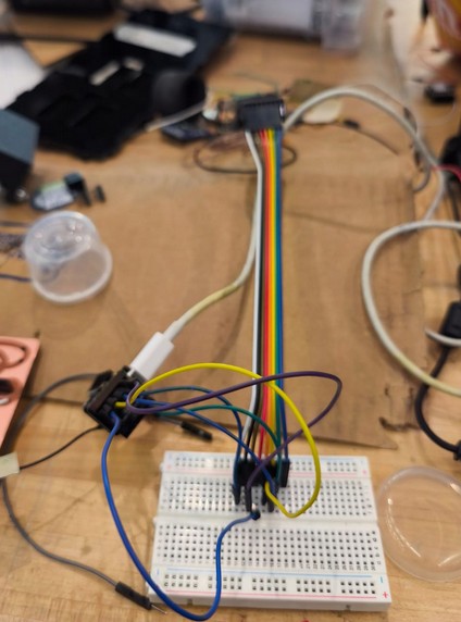
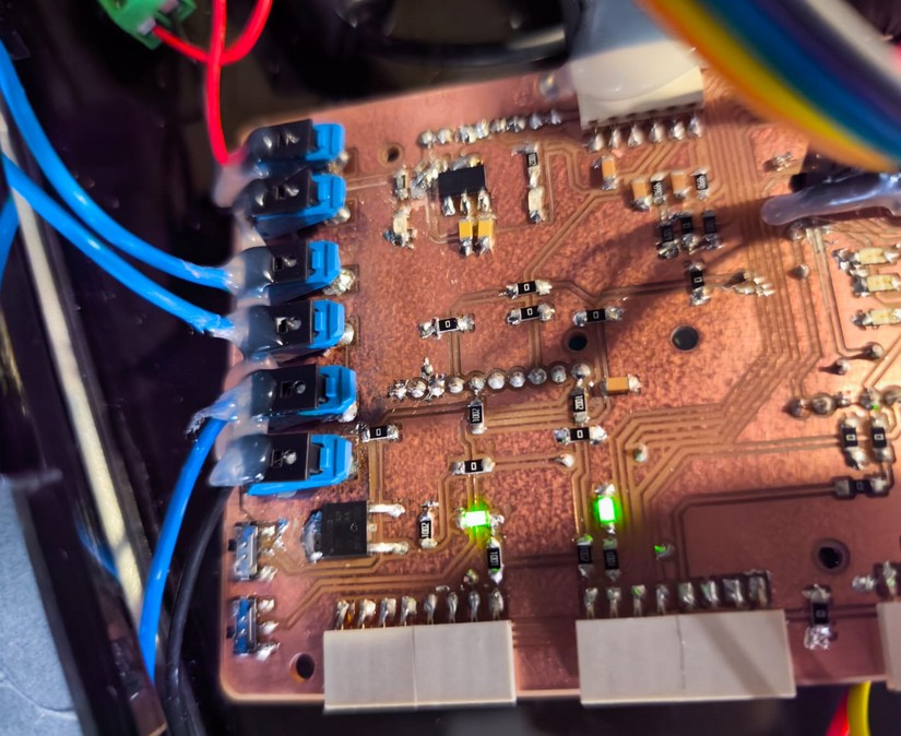
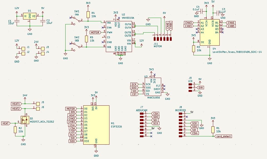
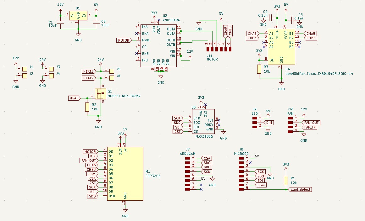
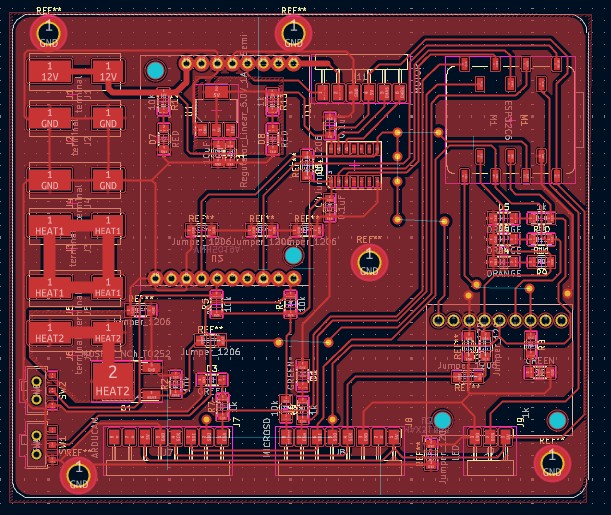
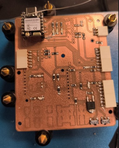
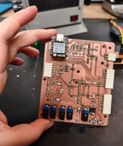
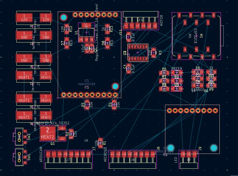
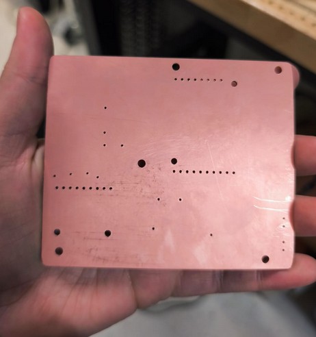
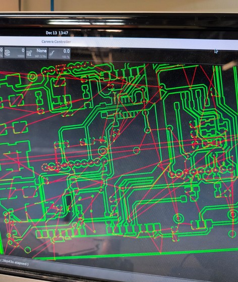
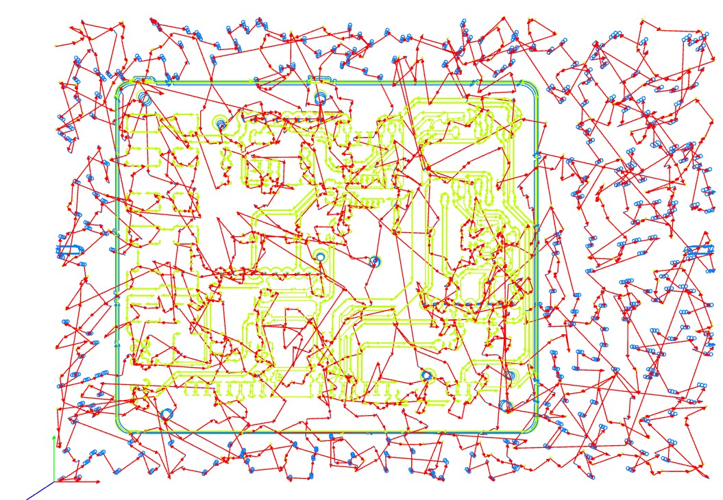
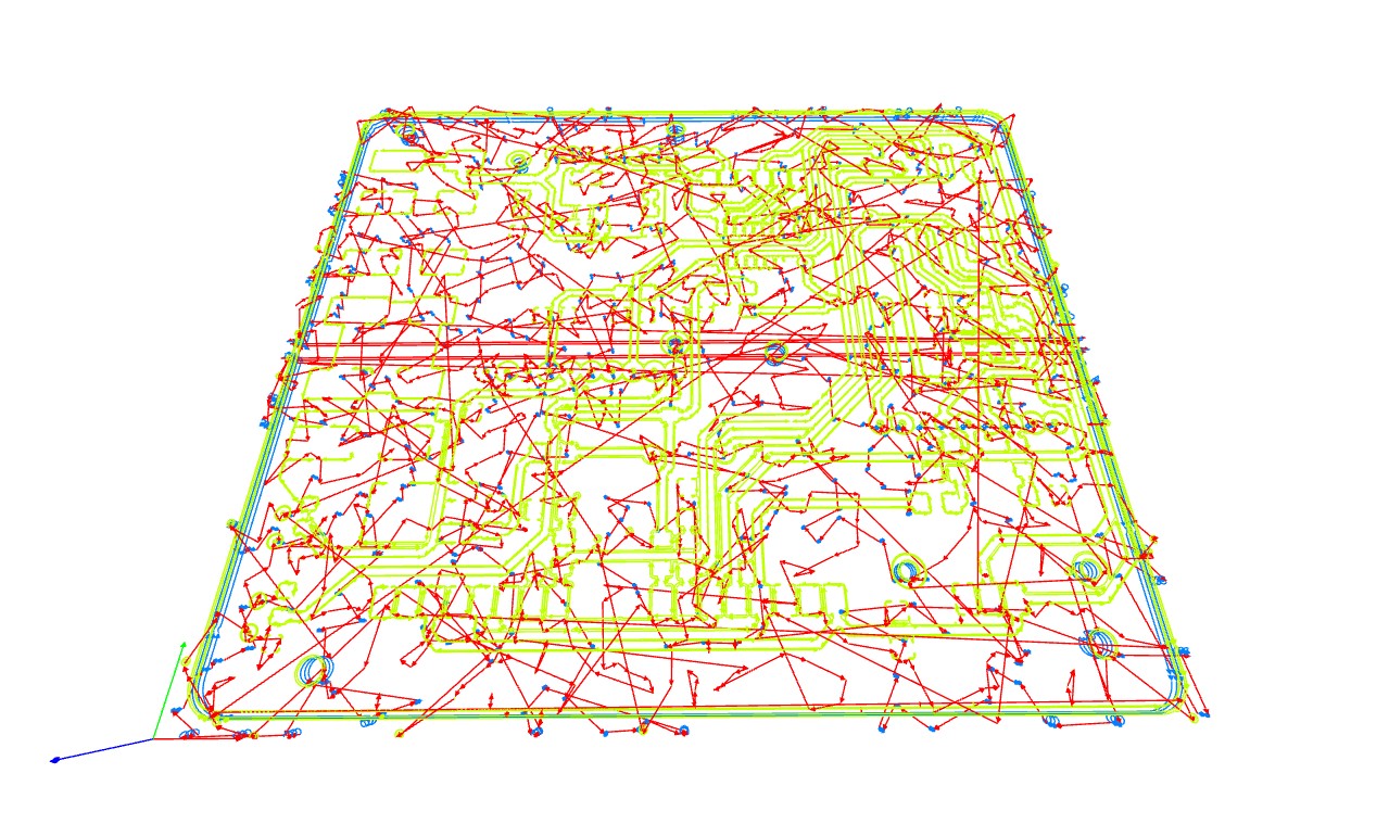
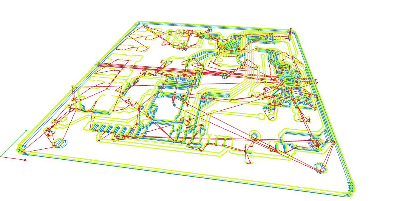
On week 4 and 5, I created a PCB which would run two motors as I need in my final project.
On week 7, I compared methods of measuring heat using thermocouples and RTDs.
On week 8, I made a new motor driver board using Pololu drivers I had.
The time to lock in is now. We need several physical things that will not be designed, and that is:
For CAD drawings, I neeed:
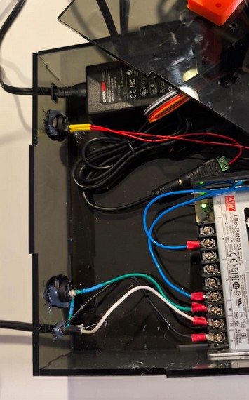
For electronics, I need
https://www.autodesk.com/support/technical/article/caas/sfdcarticles/sfdcarticles/How-to-create-a-spur-Gear-in-Fusion-360.html https://www.printables.com/model/681623-xiao-sense-case-seeed-studio-xiao-esp32s3-sense-ca
Hi if you are reading this im sorry I havent slept in a week and havent been able to finish documenting the project as I was fixing the pages before this one but i will do my best to get it done ASAP if you would allow me to
i documented by hand because documenting as ai go in the webpage has proven to be very very challenging to me
the friction of getting the images uploaded and the site running and stopping what im doing to document truly made it impossible for me to focus on work and get anything done