6.9020 HTMAA Week 08
[group work looks like this!]
Input Devices
This week's focus is to understand how devices receive signals from other devices and the world around them. Some of these involve picking up atmospheric conditions like sound waves or objects hovering nearby. Others capture direct interaction, like pressure or force applied to the sensor, and yet more describe the behavior of the sensor itself, for example its motion, acceleration, or global positioning.
The most important intuition about input devices that we reviewed is the difference between analog and digital signals. Analog signals are the more "natural" of the two; these are continuous signals that vary within their range as some kind of waveform. Digital signals, by contrast, are encoded in discrete numbers (usually a binary sequence).
 The metaphor we discussed to describe this is that an analog signal for volume might be represented as a person whispering and then shouting; in this case, the volume is represented literally by the sound of their voice. But if someon says the words "70 decibels," no matter how loudly or quietly they say it, the meaning of that volume declaration is the same.
This week, I wanted to advance my final project by approaching two different aspects of the sensing strategies I hope to implement. The first, which I address through the group assignment, was capacitive soil sensing. The second, which I explore in the individual assignment, is GPS coordinates.
Probing Input Signal
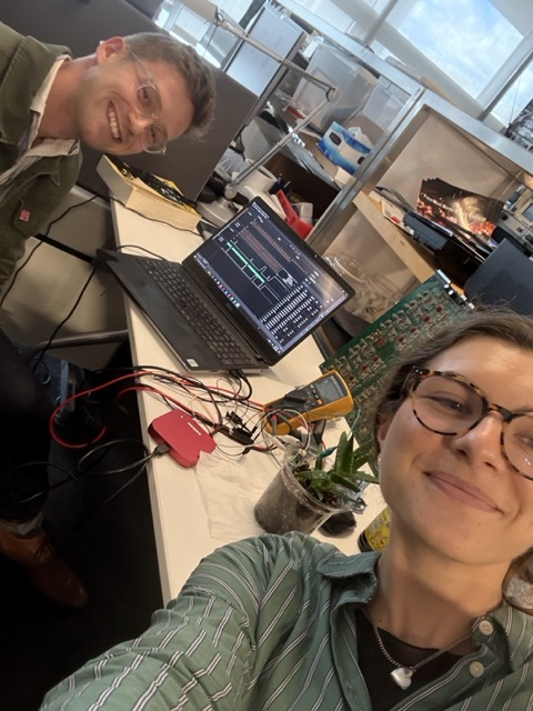
As both of us were unavailable at the group times of our respective course sections, fellow Yalie and soil-curious Ben Weiss and I teamed up to probe some input signals. We decided to explore capacitive soil sensing using the Adafruit STEMMA Soil Sensor. This device uses capacitive touch measurement to sense the conductivity of soil as a proxy for its water content.
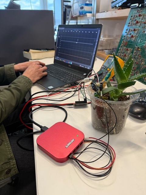 This sensor works by applying a small voltage to a conductive layer. When a conductor (like moist soil or a human finger) touches this surface, a capacitor is formed. This changes the frequency of the signal received by the sensor's microcontroller, which is then read as a measure of capacitance. While the change in signal frequency is theoretically analog, the sensor's microcontroller sends a digital signal to the main microcontroller on the board. We were able to see the analog capacitance signal (white) using Ben's oscilloscope:
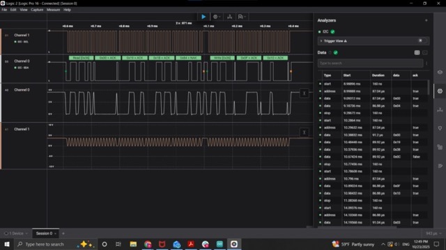 However, these measurements weren't making much sense because we couldn't see changes in the capacitance with different soil / air moisture conditions. Ben continued to explore this (and posts a more detailed account to his site) and found that the multimeter we had attached to the setup was disrupting these changes in signal. He was eventually able to sense changes in the I2C communication between the main microcontroller and the sensor microcontroller:
 In the improved visualization, the top two channels are I2C communication between the main microcontroller and the sensor, and the white channel below them is the analog capacitance signal. Thank you Ben!
The official EECS group submission for this week is available here.
Adding a Sensor to my PCB
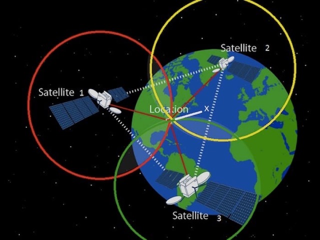
For my individual assignment, I chose to focus on GPS positioning, which is central to my final project. GPS stands for "Global Positioning System," and GPS modules use very small processors and antennae to receive signals from a constellation of 24 satellites in six Earth-centered orbital planes. GPS determines a position using "trilateration," which refers to the intersection of the spheres of signals sent out by the satellites at an equal rate in all directions. Three signals, and the (atomic) time at which they were sent, are needed to fix a position:
 The GPS module available to me in the EECS shop was the Goouuu Tech GT-U7 receiver with a 6M 51 Microcontroller. Its datasheet boasts instantaneous location of satellites and compact design relative to its power and memory. The first thing I came to appreciate about this device is that it has labels for each of its five pins (PPS, TXD, RXD, GND, VCC) on the back!
However, in spite of that helpful design feature I did manage to cause various unforced problems in soldering it to my PCB. I had created a pinhead especially for this module in my PCB from Week 6 and wanted to attach to this. I had a hard time figuring out how to solder the pins into place because I felt I couldn't reach them with the soldering iron, so I ended up soldering part of a pinhead in and then ripping it back out, which tore off some copper from the board surface.
In order to fix this, I (again) had to add wires that could connect my module to the correct pins on the microcontroller.
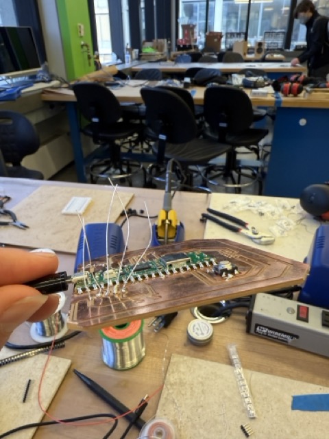 Once these extra wires were in place, I soldered the microcontroller onto them and attached its receiver to the clip-in pin.
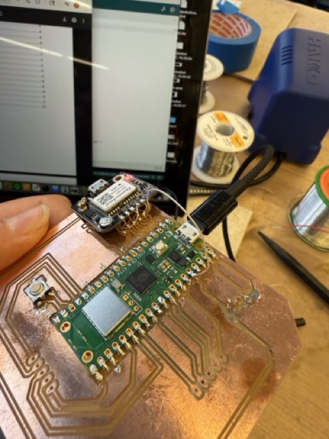 When plugged into my laptop, its red pilot light illuminated, confirming that my solder had worked!
Sensing Coordinates
In order to set my GPS working, I referred to this video by the "Wizard of West LA" explaining how to connect the module to the Arduino IDE. This turned out to be very straightforward, and I created a new sketch according to the same structure (but tracking fewer data points). With a few togglings of feedback, I managed to get my serial monitor working and received some feedback!
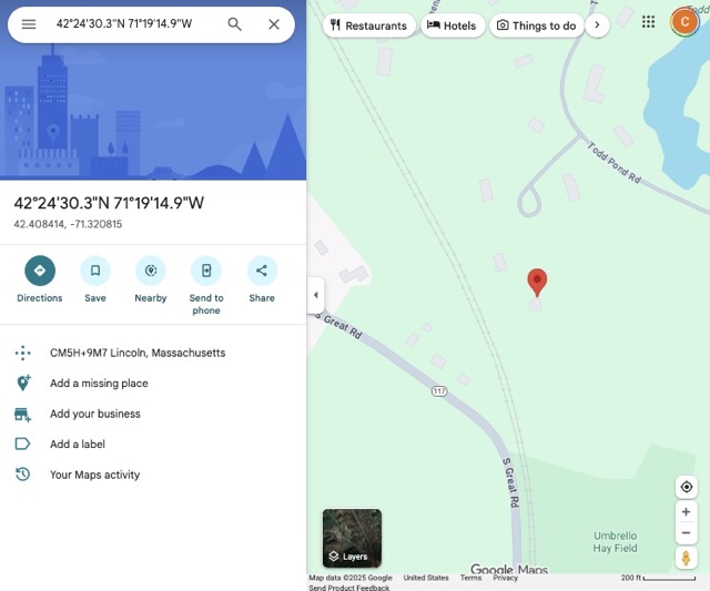
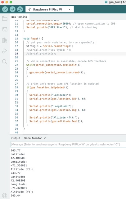 The output to the serial monitor changed constantly within an error of about 0.00001' in each direction, indicating that there are some limitations to its precision (since I was not moving). However, I checked the coordinates it gave in Google Maps and concluded that it indeed had found my house:
 The next step, for my final project, will be figuring out a way that I can record ongoing GPS locations using the module and then upload them to a map. My first instinct was to power the microcontroller from my iPhone, which has a USBC port, but this will require more research.
Trials and Tribulations
Following are some observations of the process this week, and some challenges or disappointments to record:
- It is becoming clear that soldering is not an innate talent of mine, but I am finding ways to overcome this.
- Every time I write a sketch I add a "Serial Start" message into my Serial Monitor, and it never shows up. I find this to be a really finnicky part of the process and am still unsure what I'm doing wrong, but usually I get it to respond after a few tries.
Learnings and Progress
Below is the delta between where I started on the skills for this week and where I arrived:
- The intuition of sensing signals is still quite new to me, so exploring analog/digital and capacitive sensing were very valuable. I will use these soil sensing insights in the future.
- Even though I am thoroughly addicted to Google Maps and the chart plotter on any sailboat, I hadn't known how a GPS module actually works! I recognize that smartphones use additional technologies to get highly accurate positioning, but still satisfying to know this now.
Resources and Acknowledgments
Thank you to Ben Weiss for sharing his soil sensing and oscilloscope kits for our group assignment, and for testing his electronics education skills on me (they are very good!).
 I also read this Wikipedia page of capacitive sensing, this Medium post on GPS sensing, and used the trilateration image from this article.
Design Files
Here is my GPS test .ino.