Week 2
Laser Cutter Characterization
I worked with Sara on characterizing the xTool P2 in the Mars lab.
We used a piece of the provided cardboard, which Sara measured to be 4mm thick. The P2 measured it to be 4.2mm thick where we were cutting (perhaps due to bowing).
Power and Speed
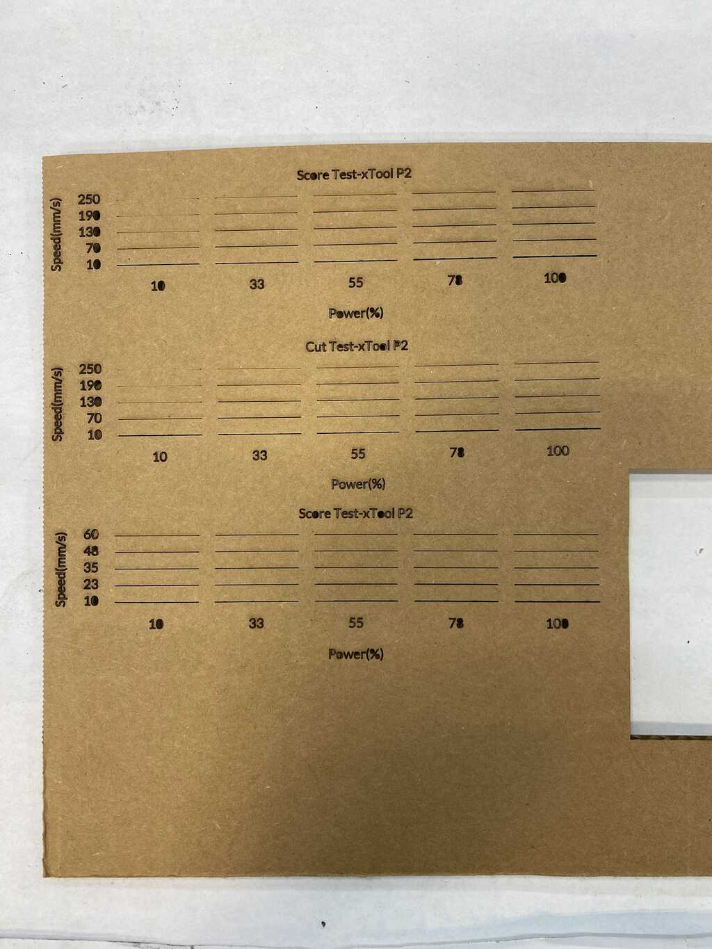
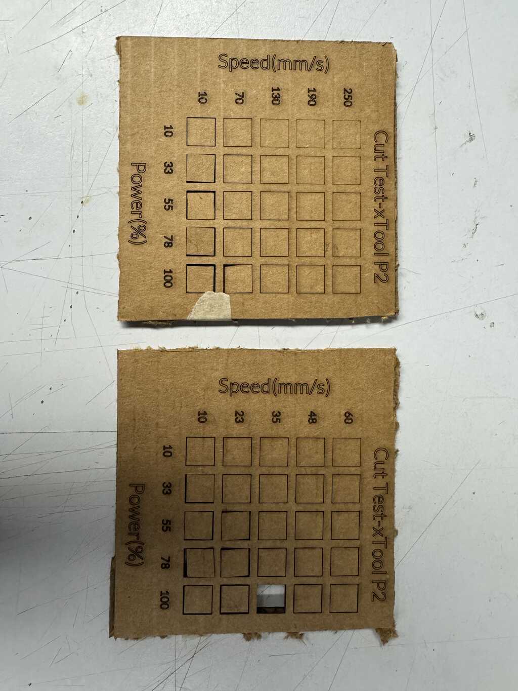
First, we started with a series of Material Tests. These tests are generated by the xTool software and sweep power and speed. We used horizontal lines of length 25mm.
The settings for the first Material Test were as follows:
Speeds (Y)
Minimum: 10 mm/s
Maximum: 250 mm/s
Count: 5
Spacing: 5mm

Powers (X)
Minimum: 10 mm/s
Maximum: 250 mm/s
Count: 5
Spacing: 5mm
We accidentally performed this test using the Score setting, so we repeated it with the Cut setting using a second Material Test.
We then performed a third Material Test with more granular speeds:
Type: Cut

Speeds (Y)
Minimum: 10 mm/s
Maximum: 60 mm/s
Count: 5
Spacing: 5mm

Powers (X)
Minimum: 10 mm/s
Maximum: 250 mm/s
Count: 5
Spacing: 5mm
The three runs, in order, are shown in Figure 1 below (photo courtesy of Sara):
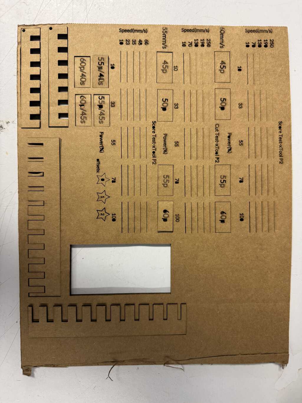
Having determined which settings cut through the material, we performed a series of manual tests using rectangles of length 25mm and height 12.5mm. The settings for the first Manual Test were as follows:
Speed: 60mm/s
Power: 45%, 50%, 55%, 60%
The lowest power for which the rectangle easily separated was 55%. The settings for the second Manual Test were as follows:
Speed: 55mm/s
Power: 45%, 50%, 55%, 60%
The lowest power for which the rectangle easily separated was again 55%. The settings for the third Manual Test were as follows:
Speed: 45mm/s, 40mm/s
Power: 55%, 60%
The lowest power for which the rectangle easily separated continued to be 55%. We settled, however, on 60% and 45mm/s to ensure clean separation.
Kerf
We also measured the dimensions of each rectangle for this test. The results are below:
| Setting | Outside Height | Inside Height | Outside Length | Inside Length |
|---|---|---|---|---|
| 55p/40s | 12.74mm | 12.26mm | 25.35mm | 24.76mm |
| 55p/45s | 12.63mm | 12.26mm | 25.09mm | 24.96mm |
| 60p/40s | 12.73mm | 12.25mm | 25.23mm | 24.77mm |
| 60p/45s | 12.39mm | 12.22mm | 25.26mm | 24.78mm |
Based on these measurements, we determined that the kerf using our chosen settings was about 0.2mm for horizontal cuts, and about 0.5mm for vertical cuts. We note however that the measurements of the inside dimensions were fairly inaccurate, and the kerf is likely smaller than this. From the original line tests, we estimate it is closer to 0.1mm.
Focus
The P2 provides an option for a “focus offset” of a positive integer number of millimeters up to 2. We tested this option and observed the kerf grow substantially (see Figure 2).
Joint test
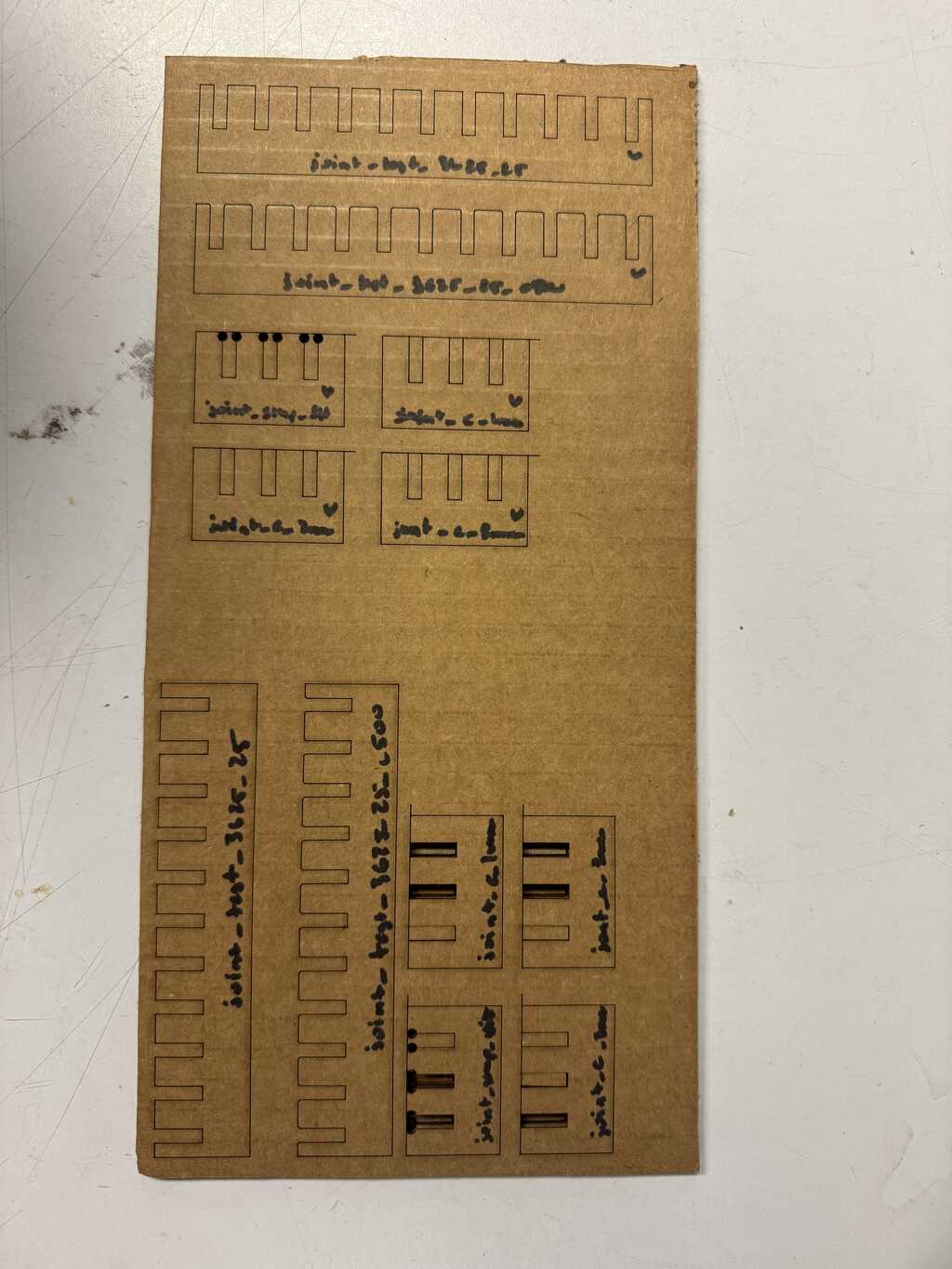
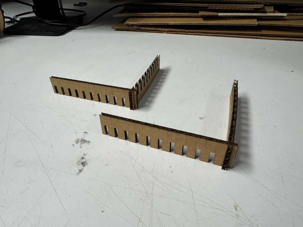
To test simple joints, we created a rake of 11 joints, ranging from 2.75mm to 5.25mm (in steps of 250μm).
We lasercut two copies orthogonally to each other. We did not account for kerf explicitly, opting instead to find the best fit empirically.
The final sheet with all test so far is shown below in Figure 2:
The 3.75mm joints fit well, but the 3.5mm joints did not fit at all. So, for the next test, we re-parameterized the pattern to range from 3.5mm to 3.75mm (in steps of 25μm, just under 1 thou). We also created a version with 500μm chamfers, on Neil’s suggestion.
New Cardboard
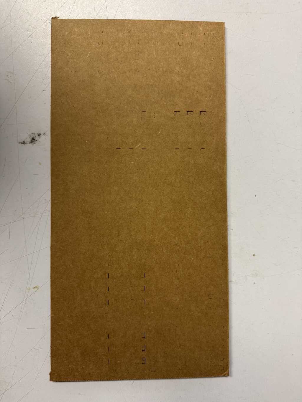
Having finished our first sheet of scrap cardboard, we cut the next set of takes on a new sheet. To our dismay, the laser did not cut all the way through.
We realized that there were two types of cardboard, with the majority of the stock being like the latter. This new cardboard measured 4.29m thick.
We did a new series of material tests to determine the power and speed.
In honor of Pareto principle, we picked a power of 80% and a speed of 20mm/s.
Using these new settings, we picked up where we left off.
We determined that the best fit was 3.75mm, and that the direction of cut did not matter. We also determined that the 500μm chamfers helped assembly. Note again that we did not account for kerf explicitly, but rather determined the optimal value to use empirically.
Construction Kit
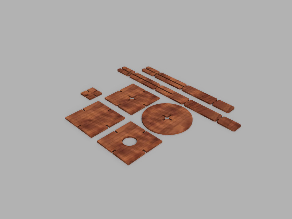
I designed a construction kit based on square tiles and cross-shaped rods, both using the joint parameters found. Since I explored FreeCAD in Week 1, I used Fusion for this week.
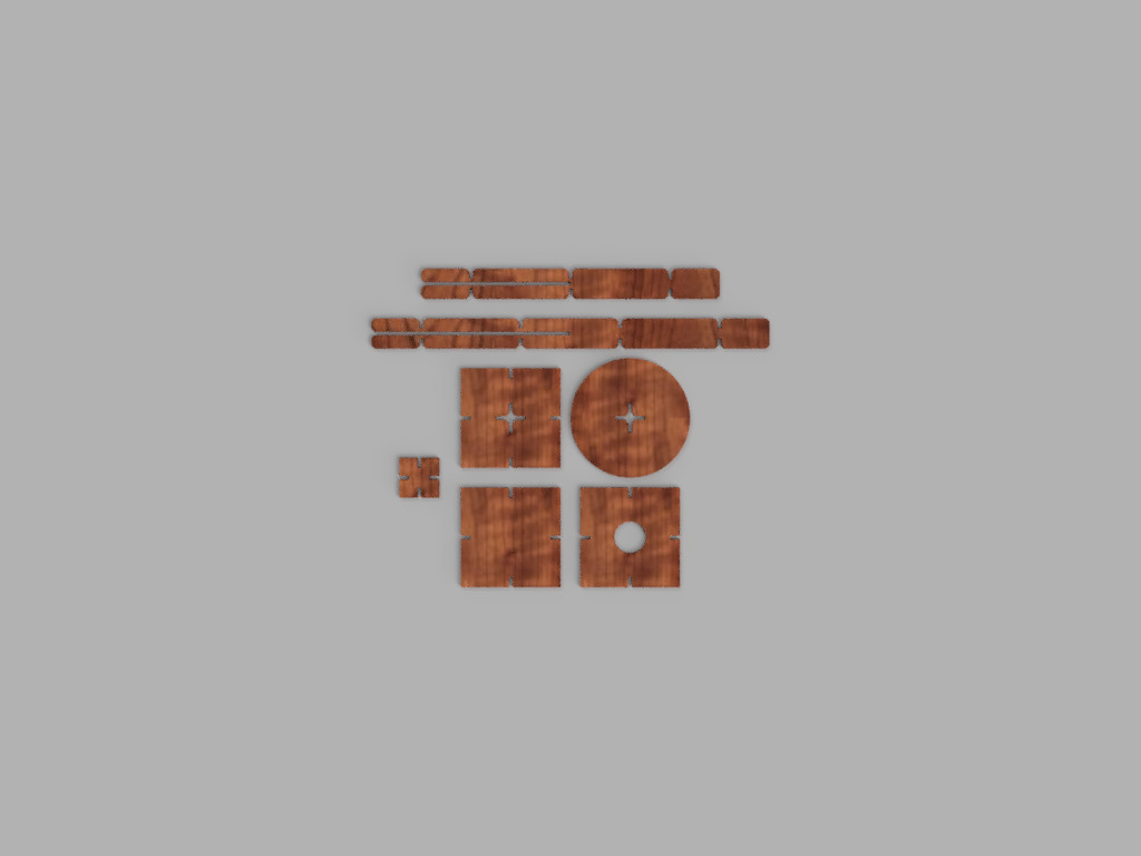
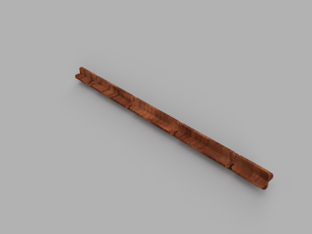
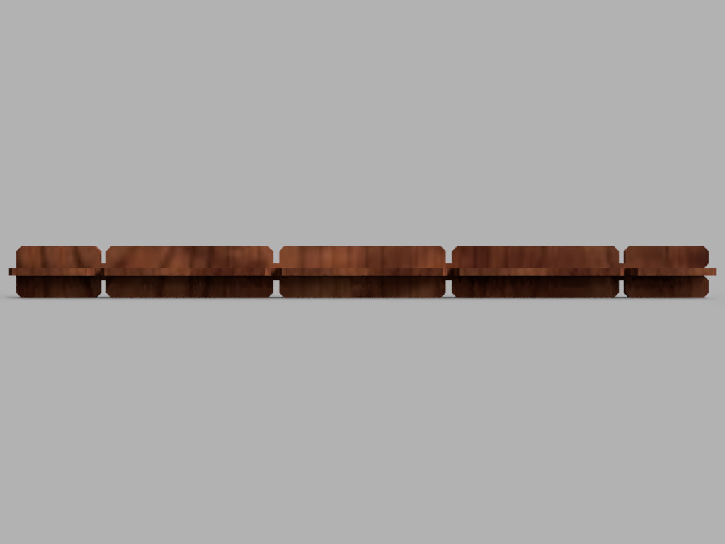
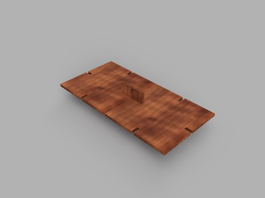
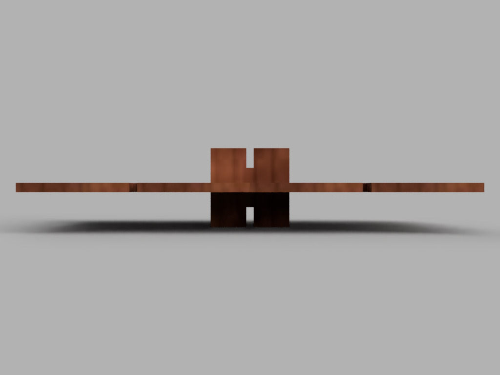
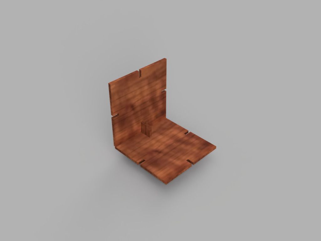
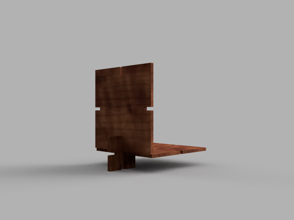
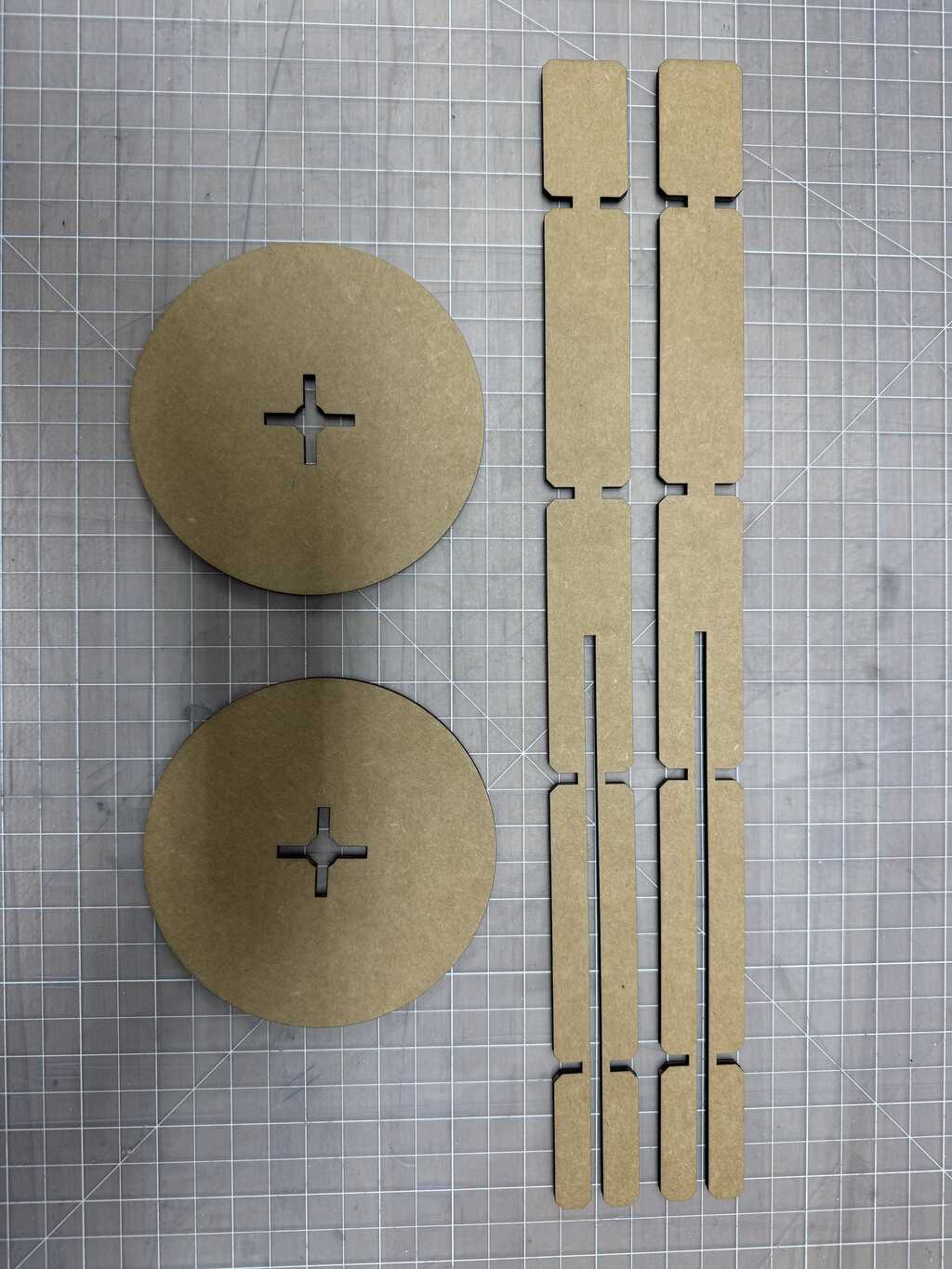
The initial parts are shown in Figures 1 and 2 below (rendered in Cherry for lack of Cardboard in Fusion):
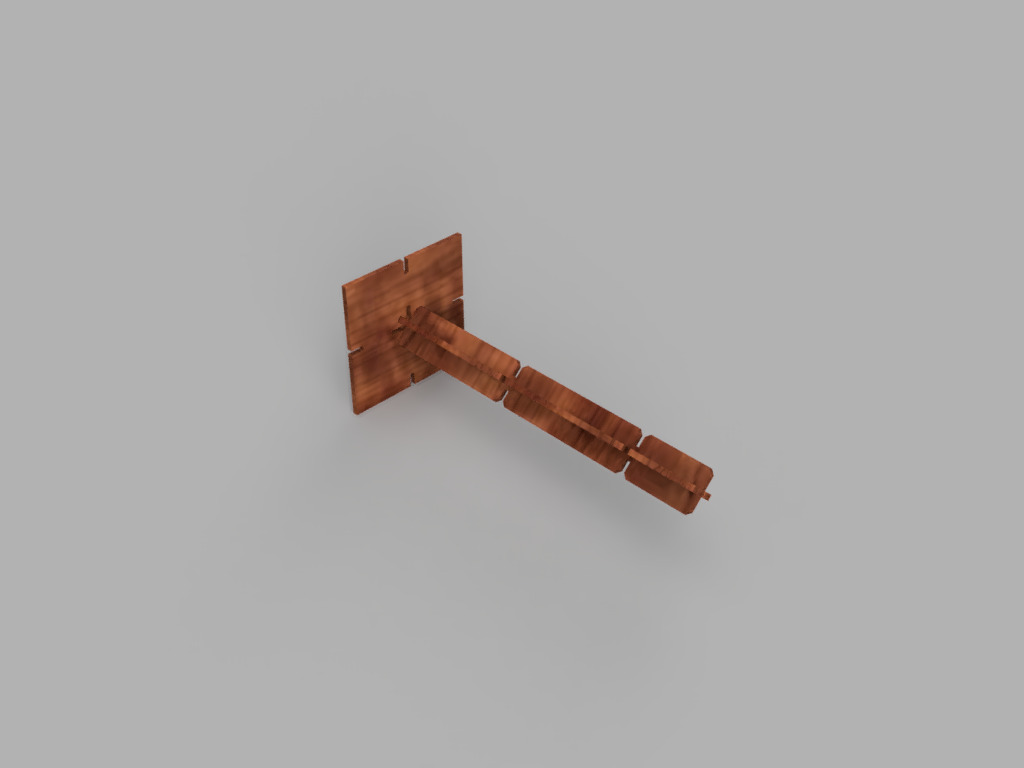
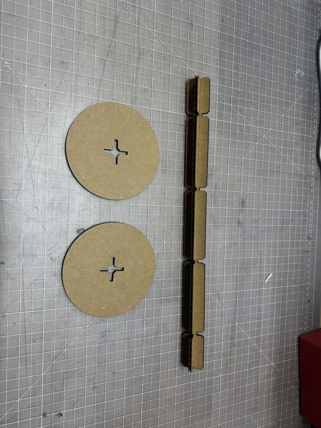
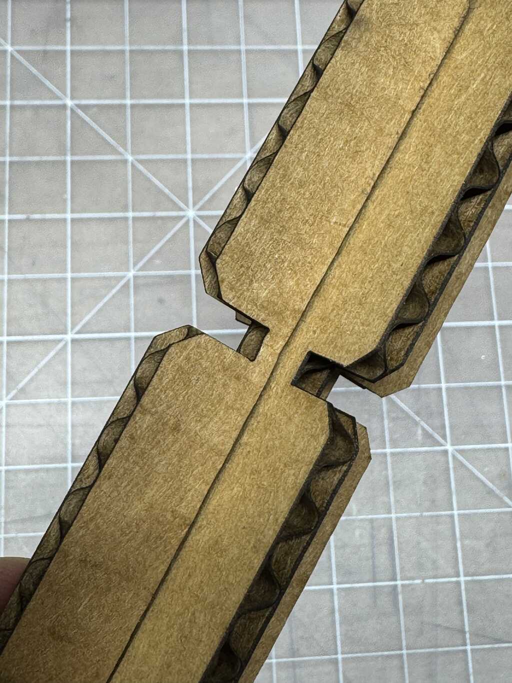
The two half-rods at top mate with parts like themselves to form full rods. Two sizes were created (3-long an 4-long), but more sizes can be made as well. A completed 4-rod is shown in Figures 3 and 4 below:
The tiles connect in the same plane using the small square part on the left in Figure 2, as show in Figures 5 and 6 below:
They also connect at a right angle, but one side leaves a small (2mm) gap. This can be improved in the future by making the small part slightly rectangular. This type of connection is shown in Figures 7 and 8 below:
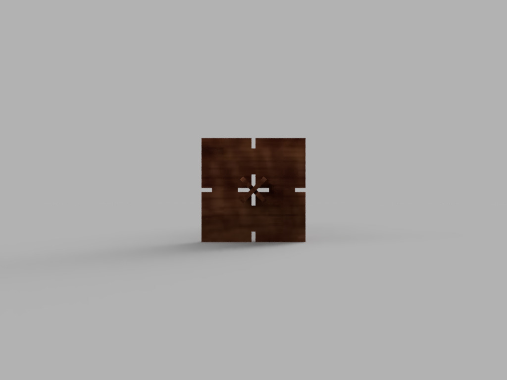
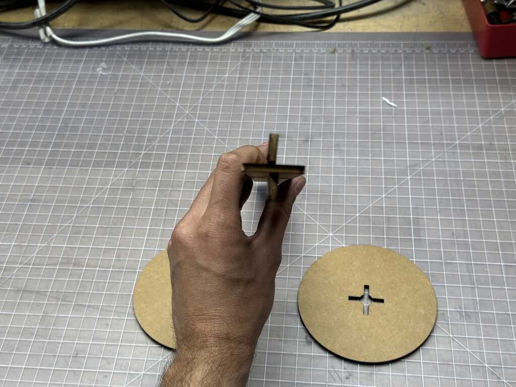
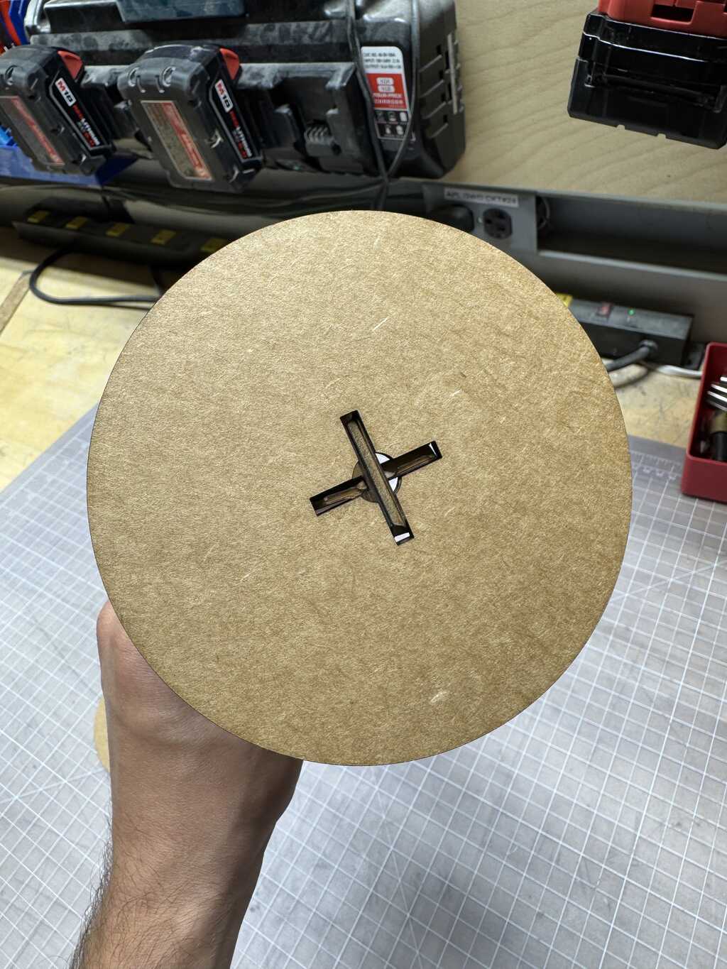
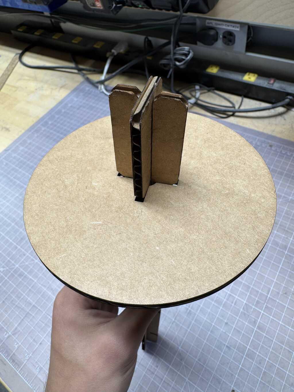
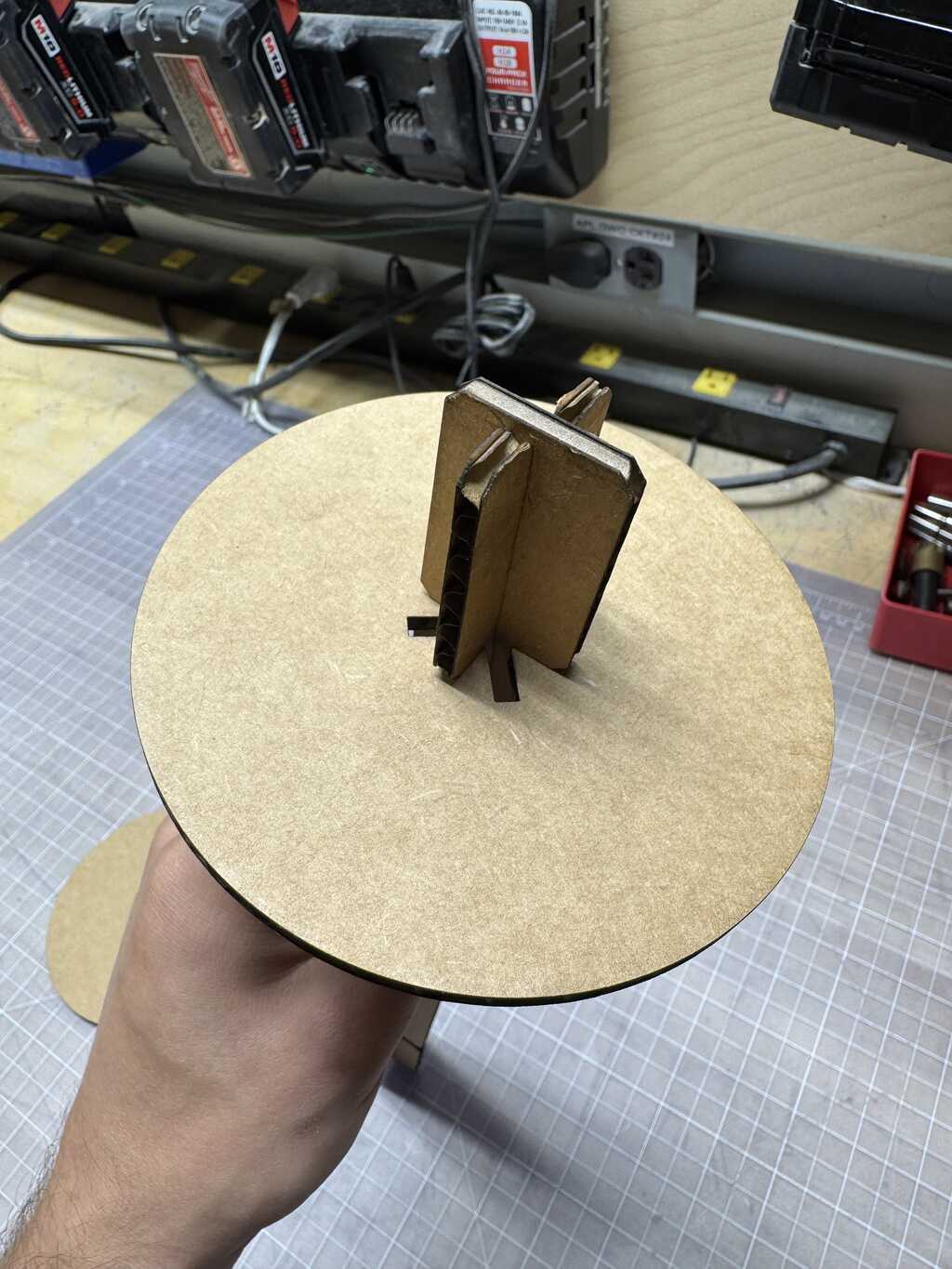
The tiles with the cross in the middle (as well as the circle) can also connect to the rods. The connection is achieved by sliding the tile onto the rod and turning it by 45 degrees at one of the notches. The notches are spaced at the same cadence as the tiles. This type of joint is shown in Figures 9 and 10 below:
The design is entirely parametric, with all dimensions defined in variables. A screenshot of the parameters is shown in Figure 11 below:
Assembly
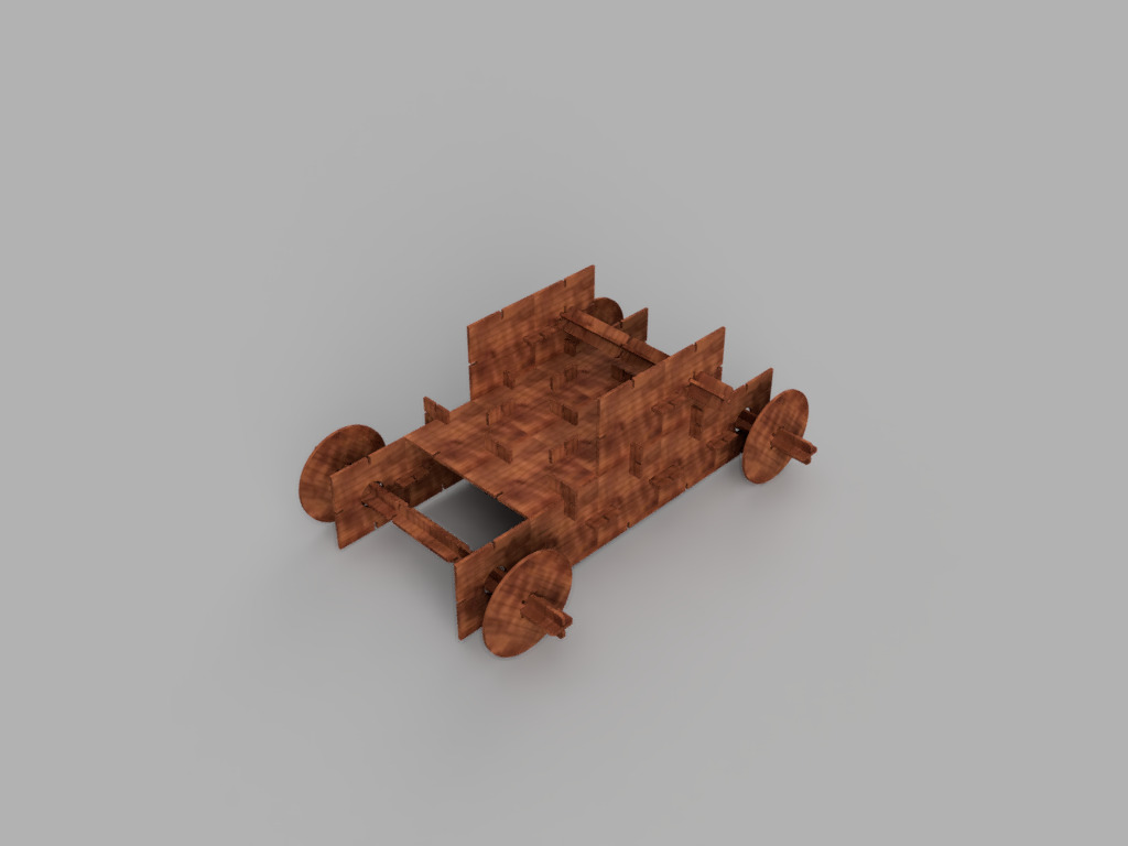
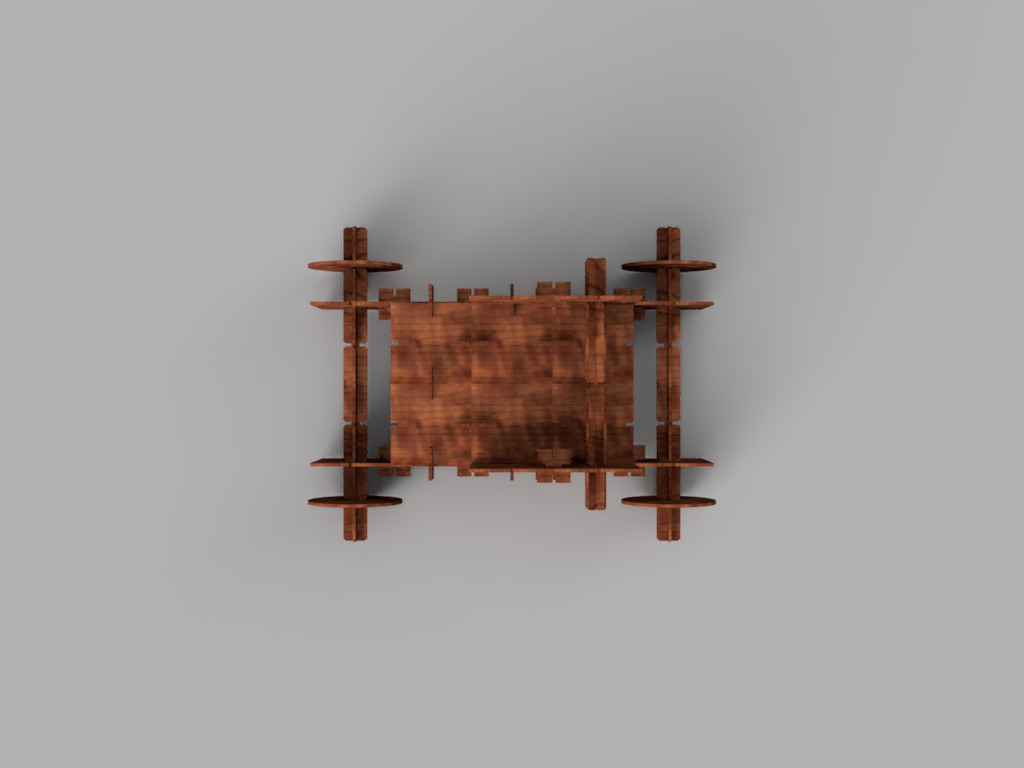
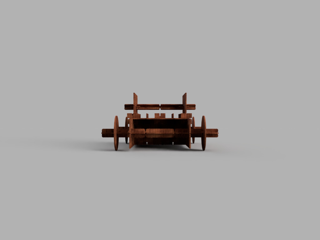
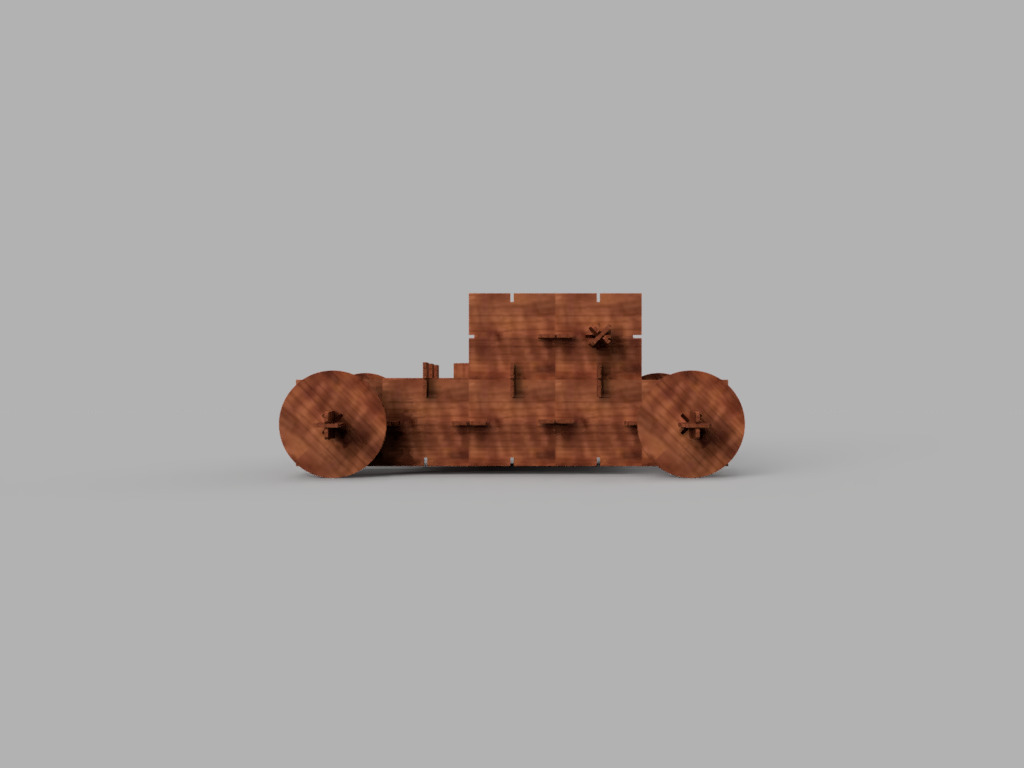
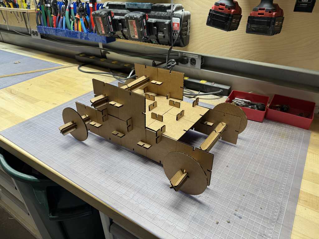
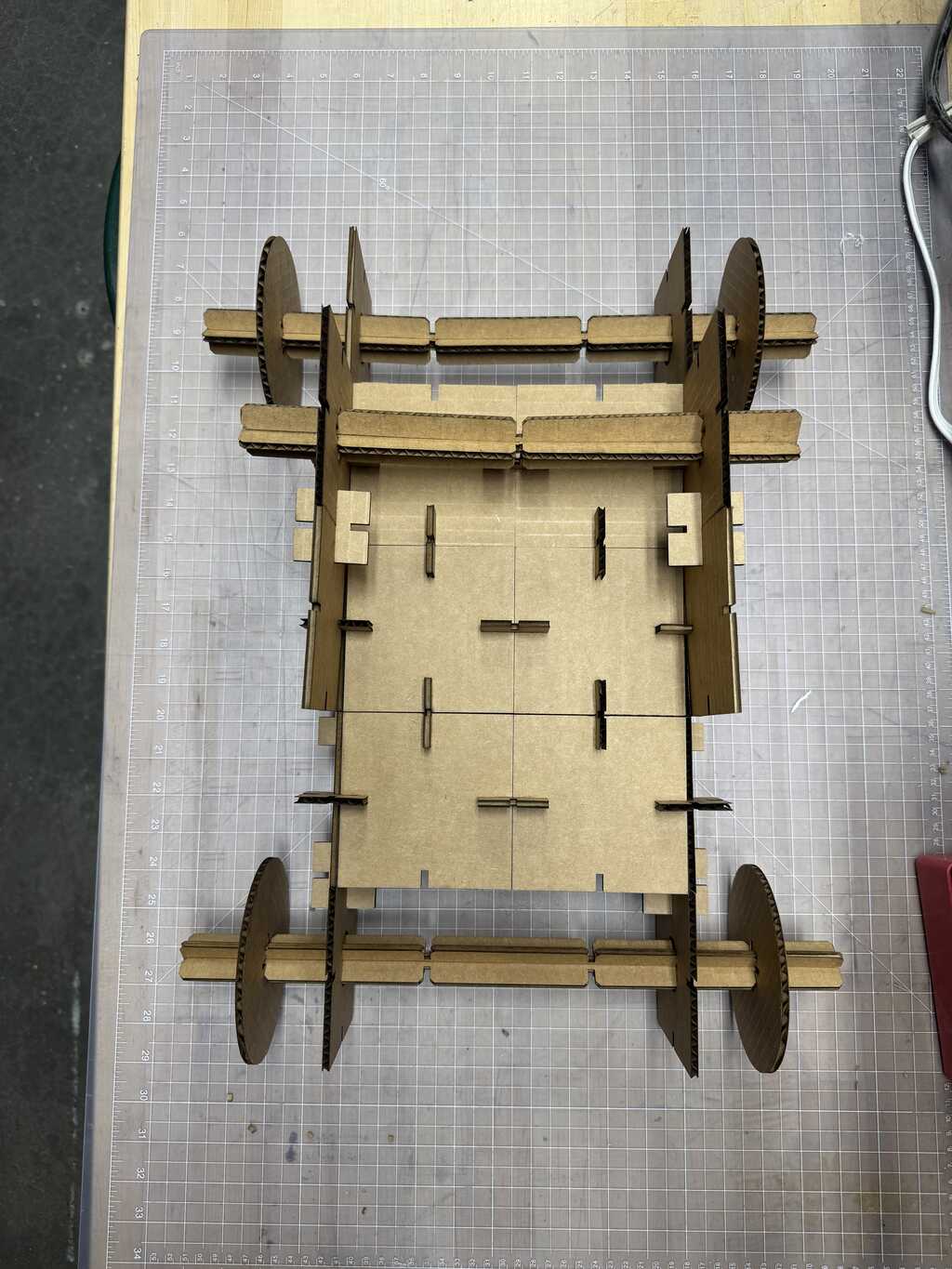
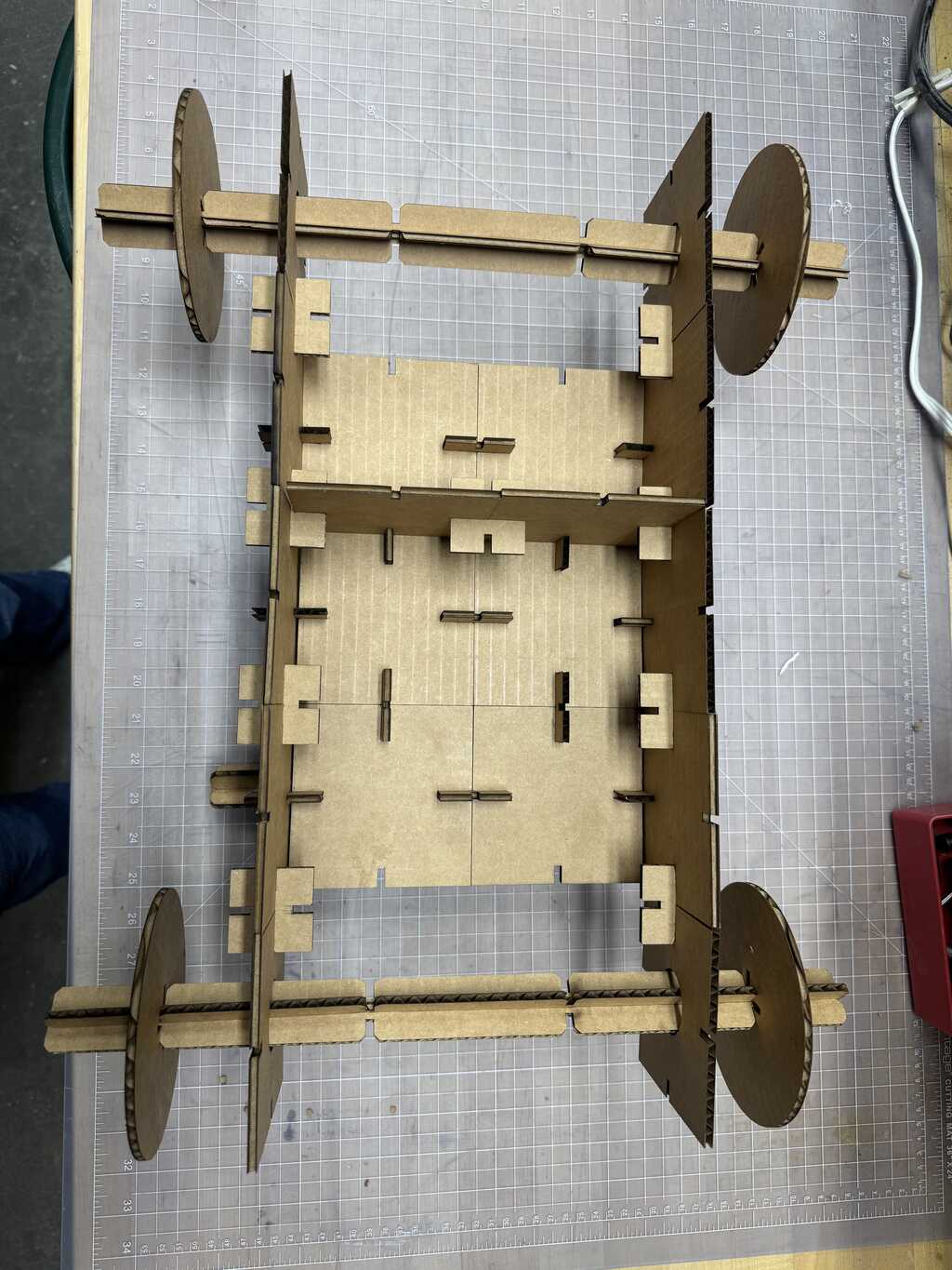
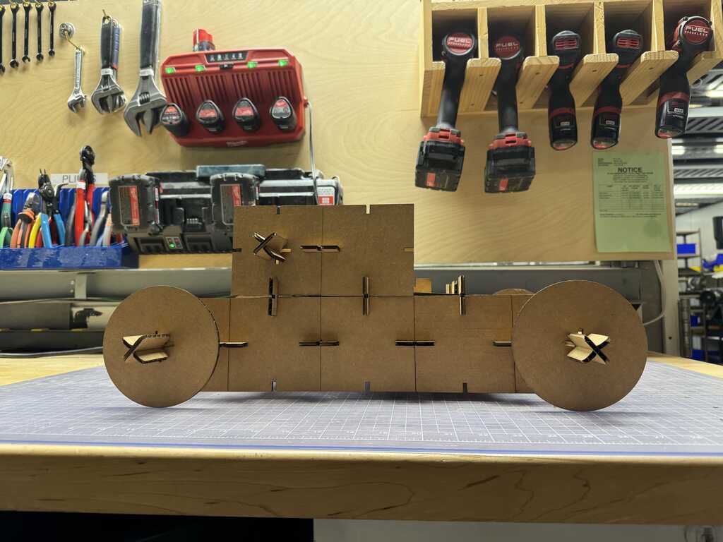
I used my construction kit to make a simple mode car. The assembly is shown below in Figures 12-15:
The total number of pieces used was:
- 3-long rod (half): 2
- 4-long rod (half): 4
- wheel: 2
- regular big piece: 16
- big piece with cross: 2
- big piece with hole: 4
- little piece: 24
I laser cut the pieces on the xTool P2 (using a Cut power of 80% and a speed of 20mm/s).
Some select photos of the final assembly are shown below in Figures 16-19:
Things that went well
Functionality
Below is a video of the car moving:
Joints
The center joints worked well. Figures 20-26 below show the construction process:
Things that didn’t go well
Cutting large things
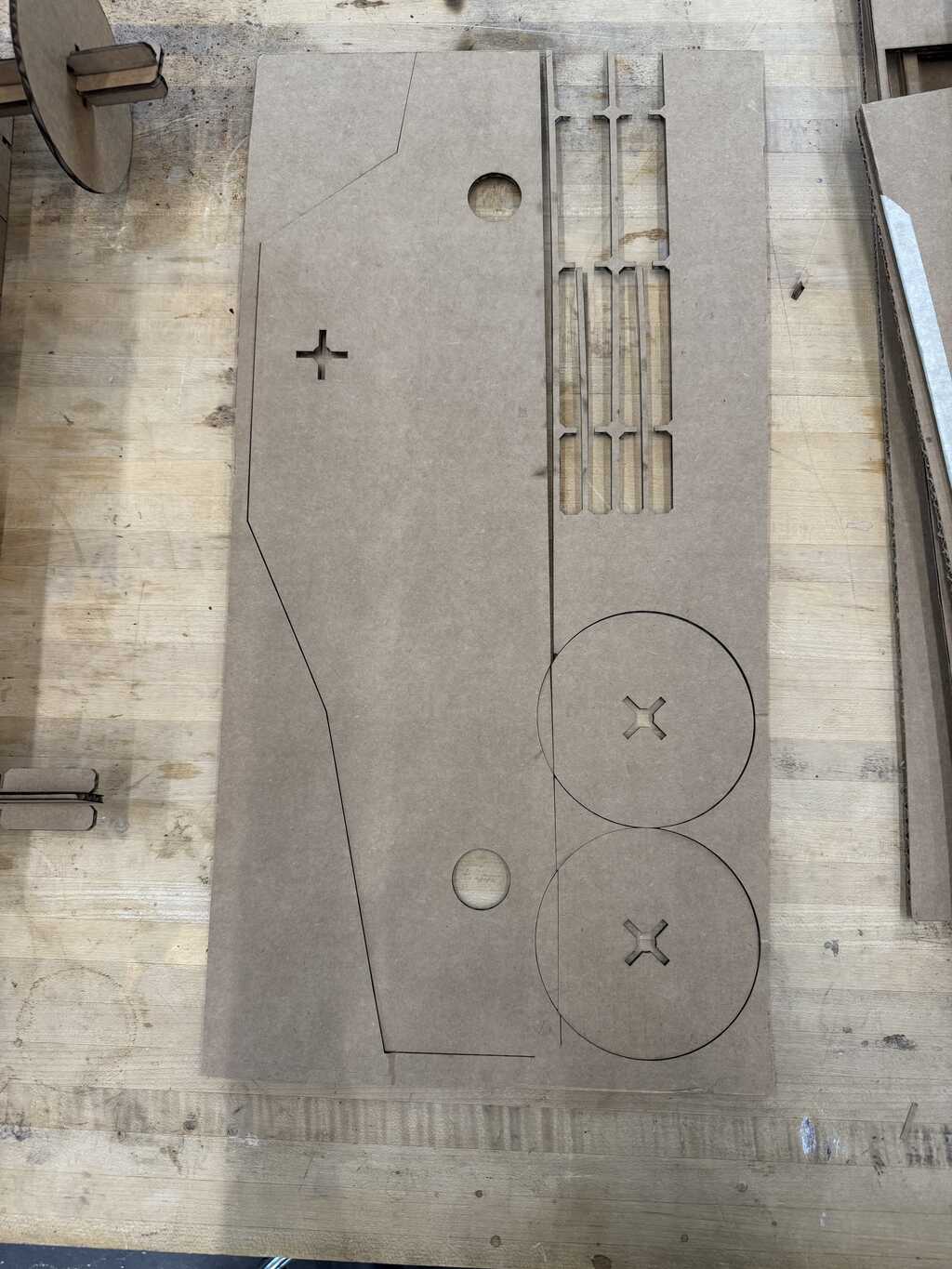
I was originally planning on cutting side pieces (roughly E36-shaped) just to test the joints and the rotation. Even though I was at the P2, I didn’t notice that the cardboard moved during cutting. The result is shown below in Figure 27:
I didn’t attempt to redo the cut, and instead progressed to the actual kit parts.
Rod Stiffness
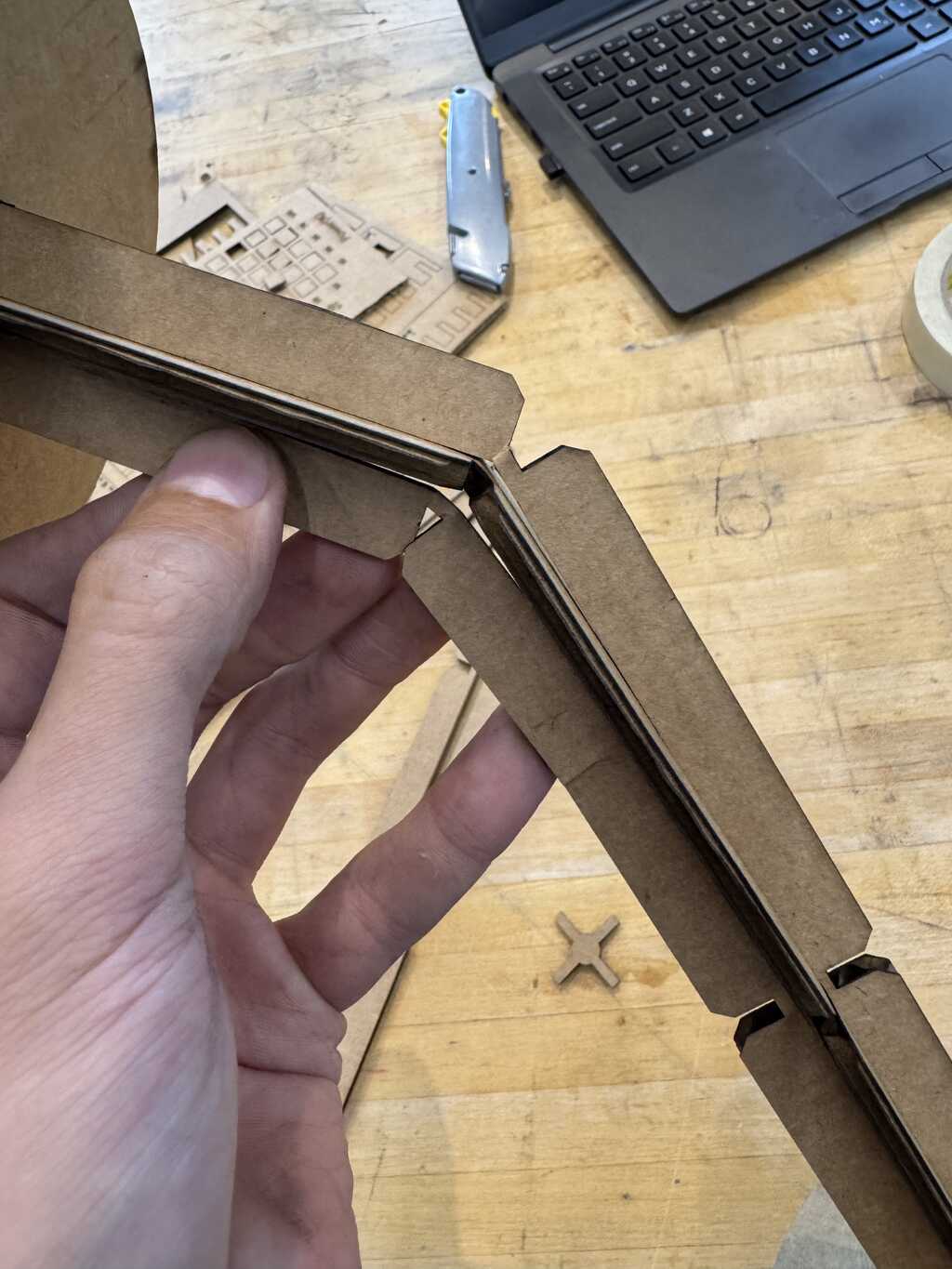
I realized during assembly that the rods were too thin. They held well when assembled, but it was easy to get them to buckle when assembling the joints, as shown in Figure 28 below:
This should be fixed by simply increasing the rod_diameter parameter by a bit,
but I did not have a chance to test that.
Assembly Stiffness
Because the stiffness of the assembly was dependent on the stiffness of the top rod, it was not as stiff as I had hoped. So, I added two vertical pieces on the bottom (see Figure 18). That fixed the problem.
Vinyl Cutting
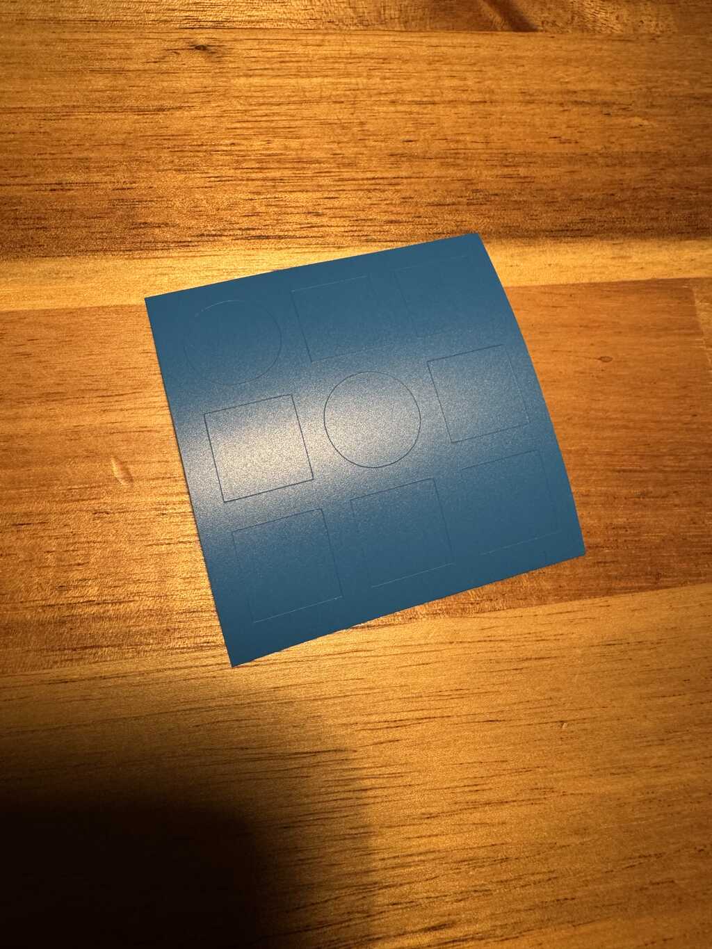
I used the Cricut Maker 3 to cut an SVG of the CBA logo. The result is showing in Figure 20:
I plan to use both the positive and the negative stickers somewhere, but I have not decided where yet.
