Result
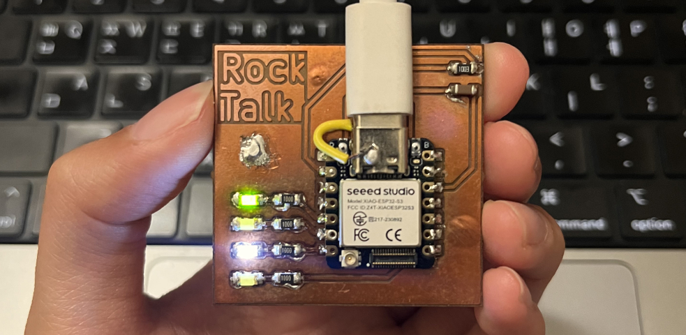
A voice‑journaling PCB that records audio input while an LED reacts to the sound.

Sadly, despite many attempts to connect the microphone, it still didn’t work, although the LED worked perfectly. This week’s documentation focuses on debugging the mic connection. Now I finally understand how to wire the I2S mic correctly. For I2S mic connections, keep these points in mind:
- i2s mic is bottom-connection component and hard to solder. We can use the solder paste and heat gun for it.
- For small components, we can edit the footprint in our pcb design to adjust the design in the milling machine setting(a.k.a endmill size).
- For the i2s mic, it needs a small hole in the bottom.
This week's HERO
Huge thanks to Kristof for helping me identify the PCB design issues, teaching me how to use the heating tools, and guiding me through the debugging process.
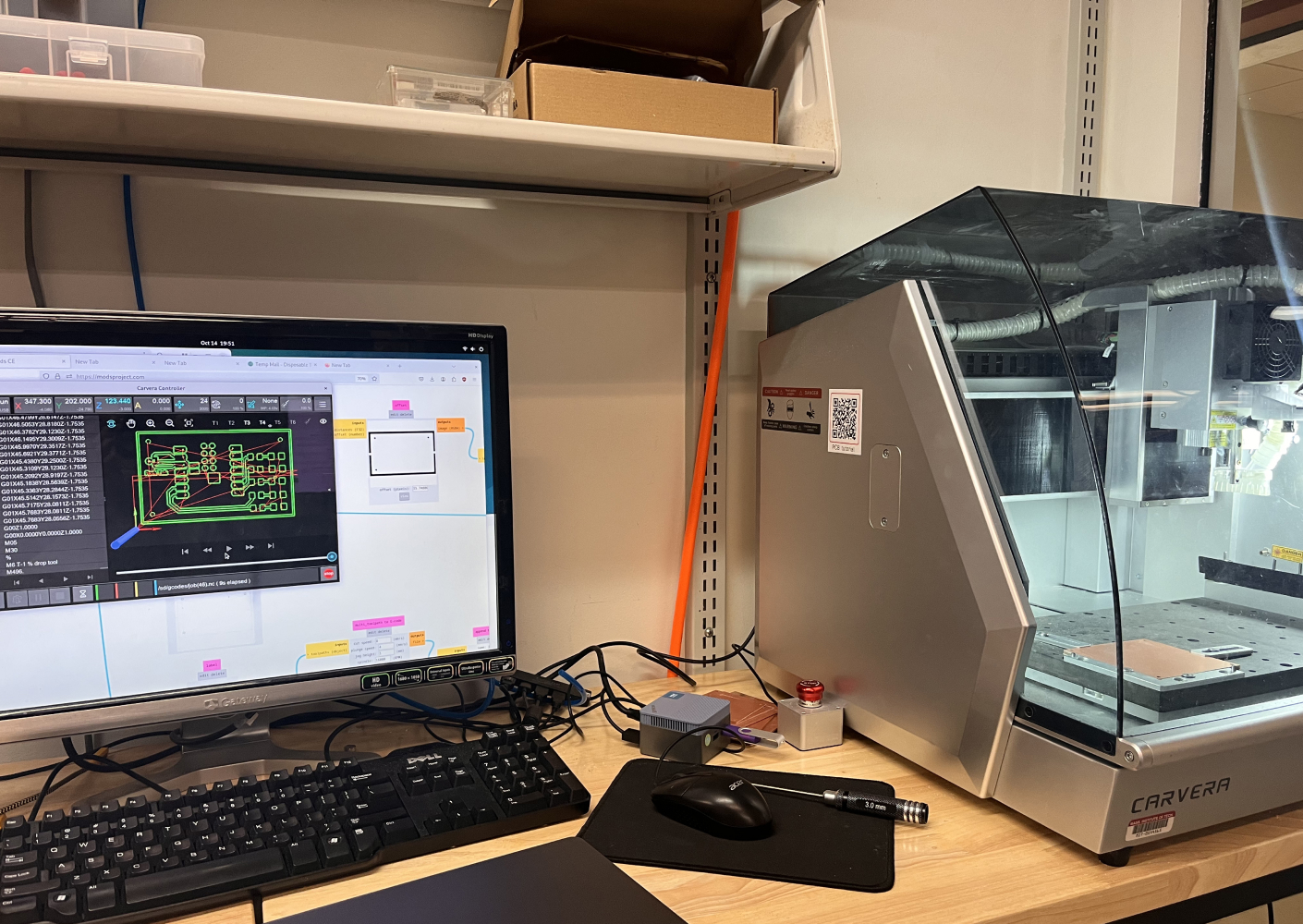
Basics of Milling Machine
Group Assignment
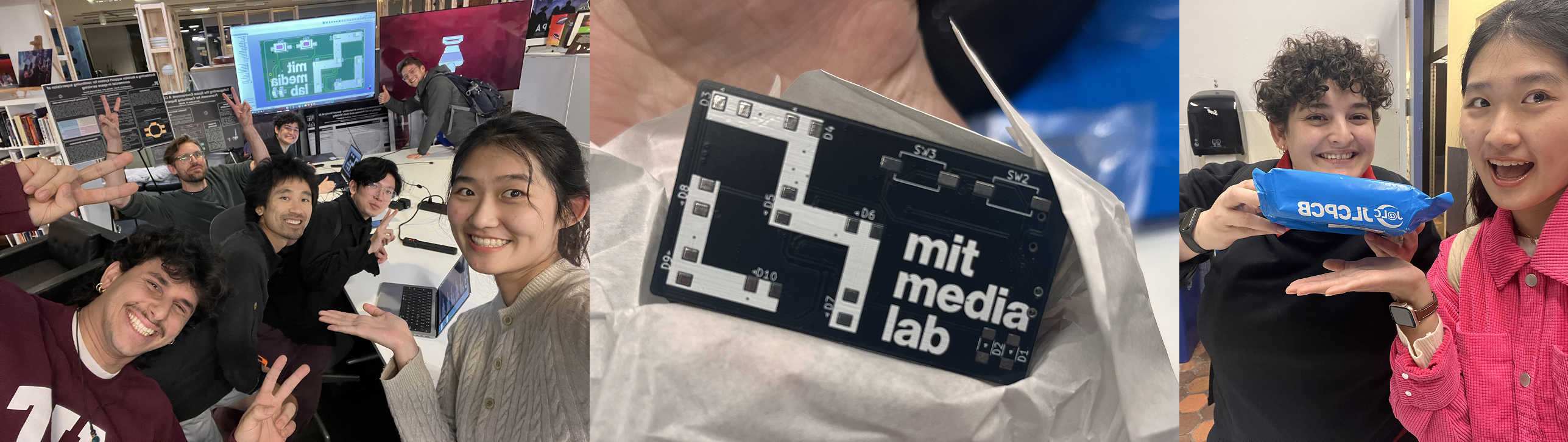
- For the group assignment, we characterized the design rules for our Carvera PCB milling machine. We started by reading the tutorial by our TA Quentin, then started producing a test PCB to understand the machine's capabilities. Our first run resulted in large amounts of burrs along the edges of the traces. We learned this was due to a damaged endmill and subsequently learned how to replace the bit. The machine is able to consistently handle traces down to 0.2mm.
- We also submitted our cuttiest Media Lab PCB Design to JLCPCB
Export the file
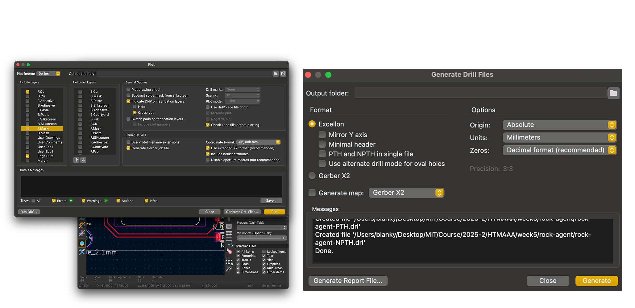
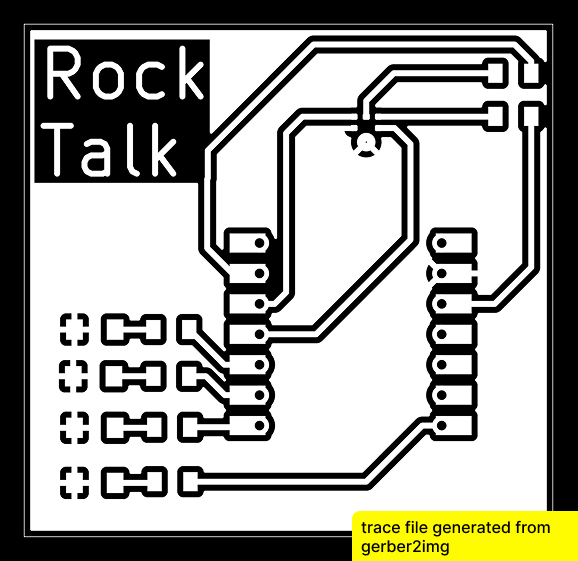
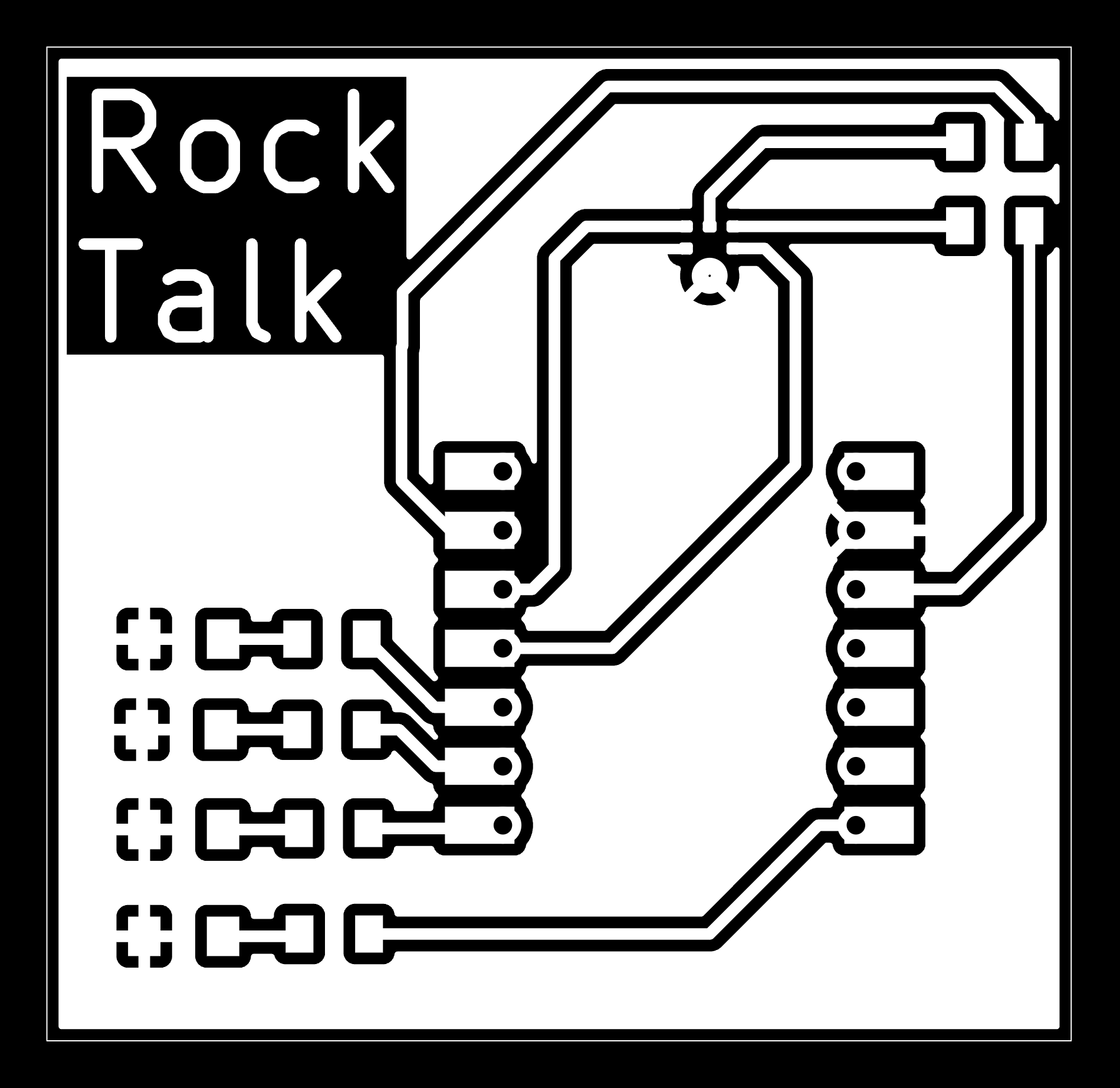
In KiCad, export your PCB design as both Gerber and drill files. Upload them together to Quentin’s gerber2img tool to convert the copper, edge‑cut, and drill layers into PNGs.
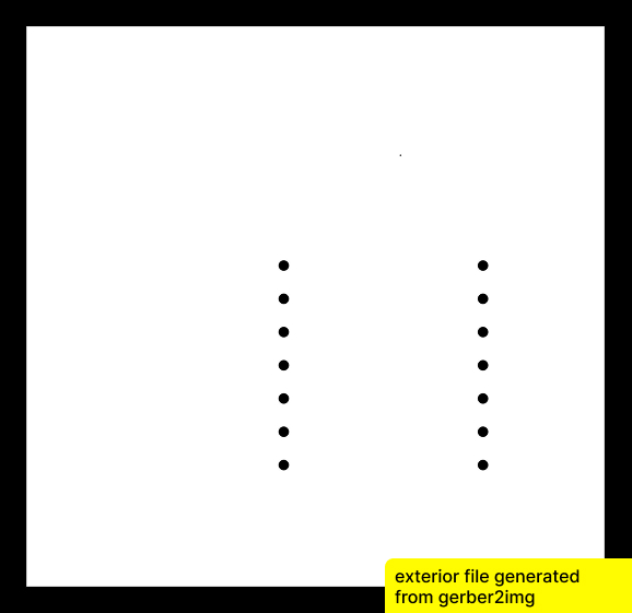
- For the exterior cut, I used the "Black and white" setting and checked "Fill edge cut" to create a solid outline including the drill holes.
- For the traces, I used the "Black and White" setting only.
Using Cavera
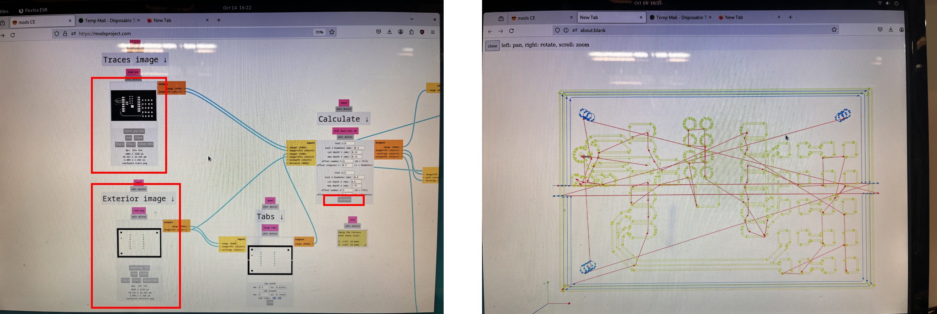
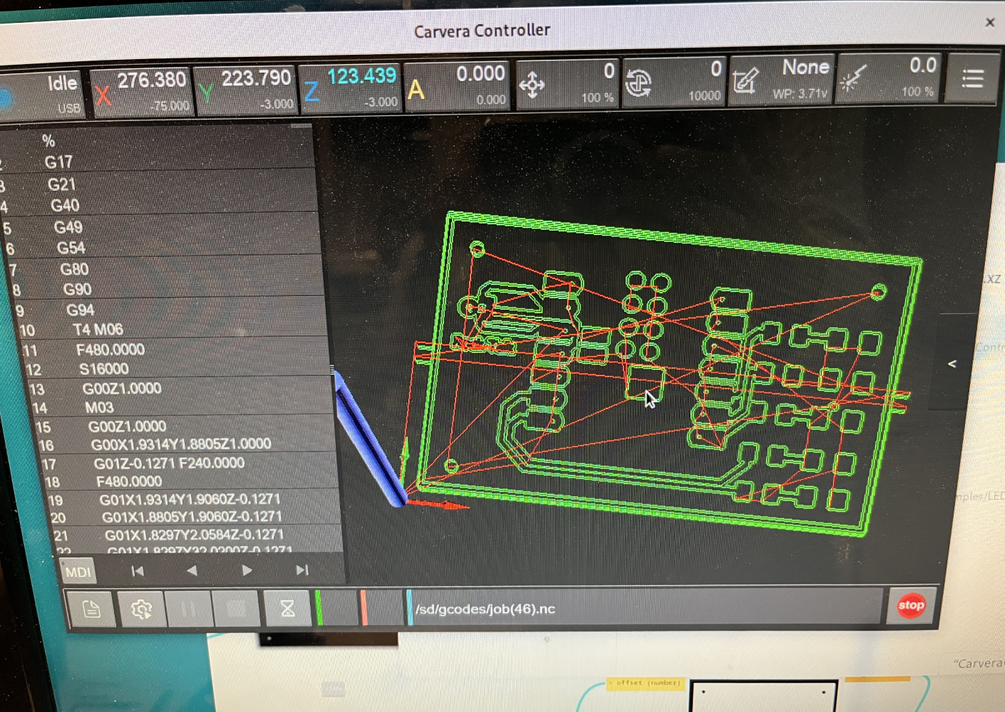
Use Neal’s modsproject with the Carvera 2D PCB module to generate the final G‑code for the milling machine. The interface is straightforward; simply follow the workflow.
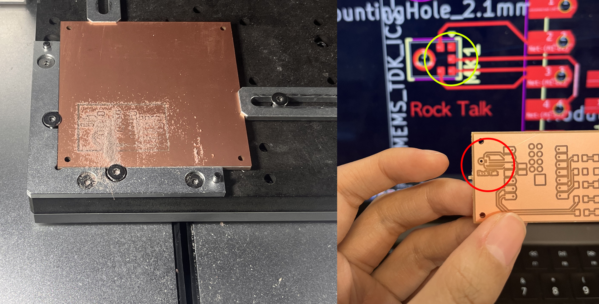
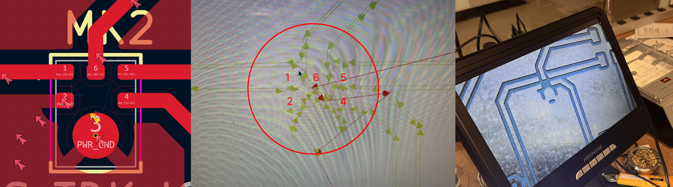
After sanding, the PCB looked clean, but the microphone’s five pins were not isolated from one another. I needed to revise the design.
Attempt 01: Redesign for Mic
Design
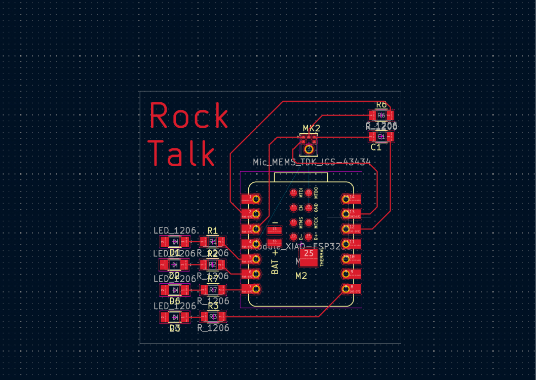
I updated the PCB layout so the mic and ESP32S3 could be connected properly.
Soldering the mic
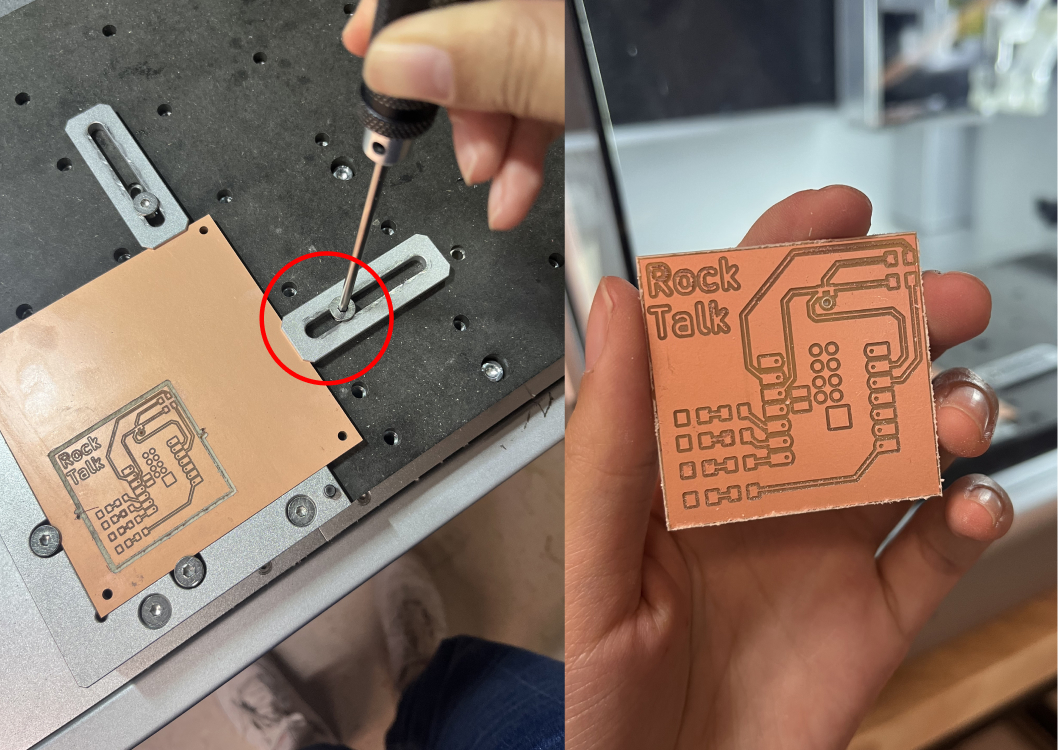
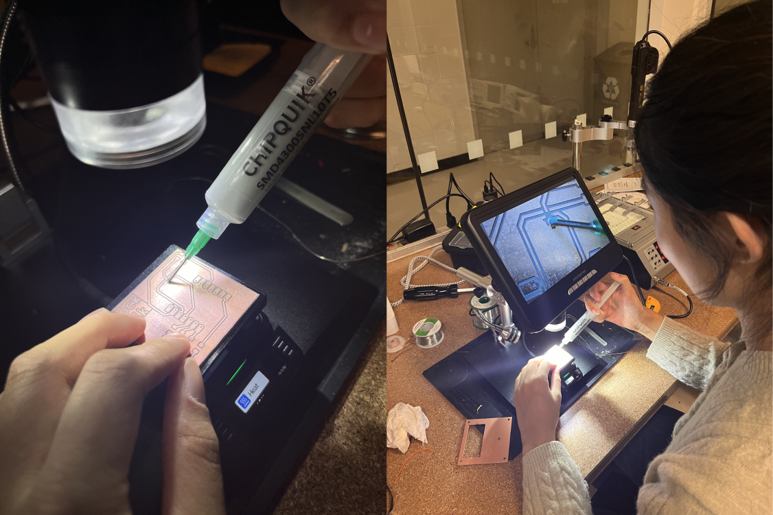
When using the milling machine, clamp the board firmly to ensure the surface is perfectly flat with no lifting.
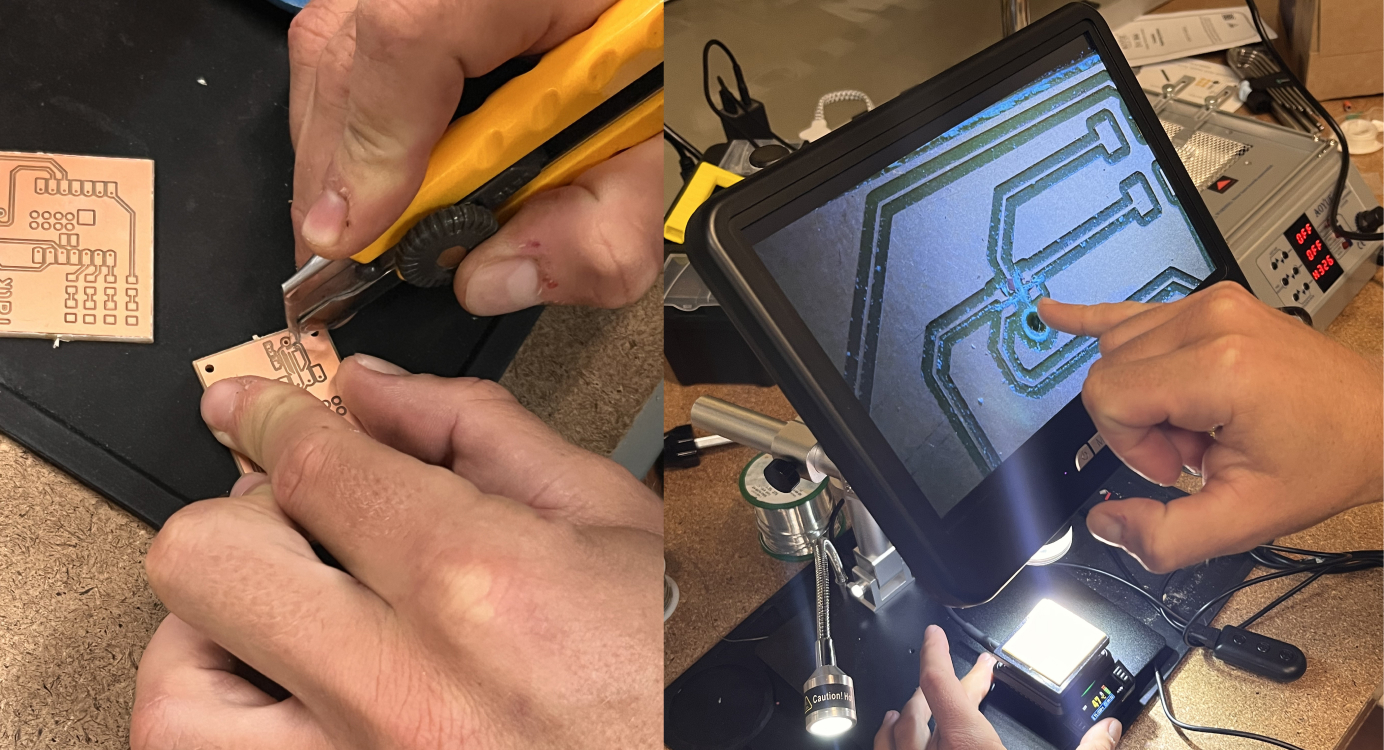
The milling machine struggled to isolate the five traces, so Kristof suggested manually separating them with a knife.
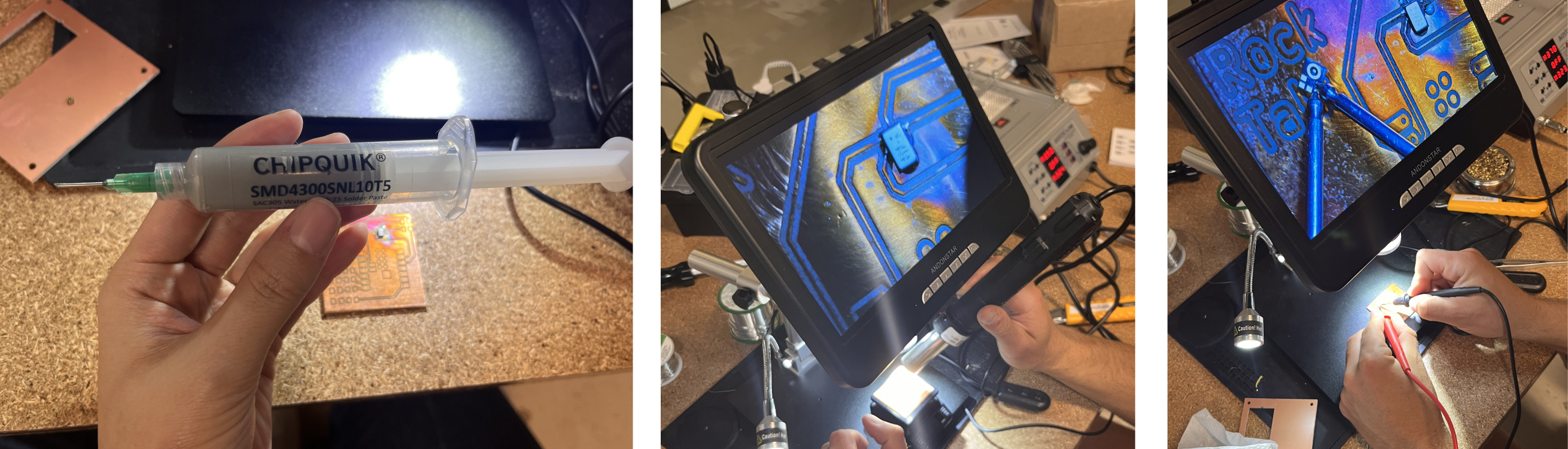
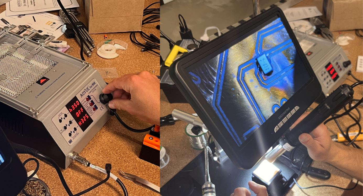
Because the microphone’s pins are on the underside, I used solder paste and a heat gun. I initially set the heat gun to 320℃, but it began discoloring the copper board, so I lowered the temperature to 300℃.
Unfortunately, the mic pins were too small, so the traces still couldn’t be isolated properly.
Attempt 02: Debugging Mic
Changing the Footprint
I updated the mic footprint to increase the spacing between pins. Now the traces are clean and fully separated!
Soldering with the heat
I used solder paste to attach all the components with a heat gun and, at first, a heating plate.
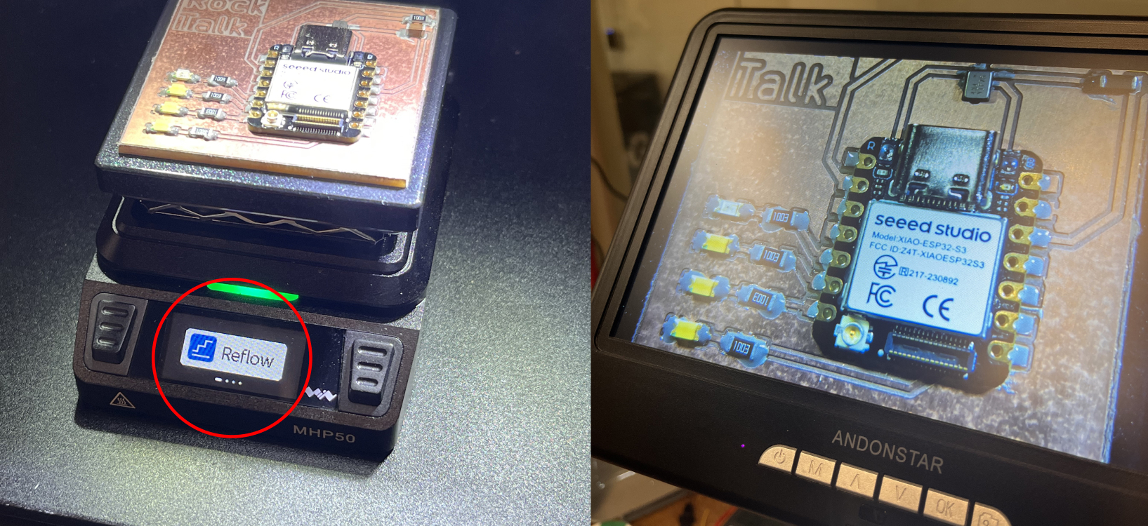
NEVER USE HEATING PLATE WITH COPPER-CLAD BOARDS. It can easily overheat and warp the PCB. Still, I documented the steps for anyone working with other materials.
- Place the solder paste
- Place the components.
- Put the board in the heating plate with the Flow mode. It will heat up and then start cooling automatically. I used Mini Brass Hot Plate Preheater.
- The solder paste will automatically change it's status and attach every components.
- Do extra soldering.
After using the heating plate, I realized it had burned the copper board. I switched back to using only the heat gun.
- I set the heat gun to its lowest airflow.
- High temperatures are risky, so I used 350℃ and waited patiently to allow the solder paste to reflow without overheating components.
Appendix
Learning from Failures
- Never go on a trip in the weekend.....
- Manage the timeline!! Never think you will succeed in first attempt.
- Keep in mind for the USB port connection while designing
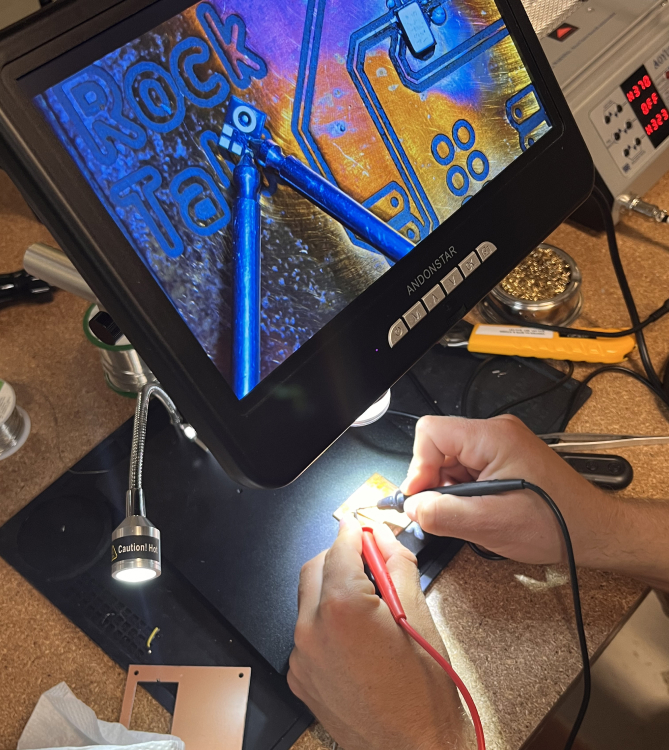
- Step-by-Step debugging is important. Using multimeter for design.
- After milling, test all voltage lines and trace continuity with a multimeter. Always check before soldering to ensure:
- (1) connection with the GND
- (2) Check the LED light with the ardunio blinking code first.