
Week 1
Principles & Cutting · HTMAA 2025
Week Highlights
Laser Cutter Characterization Results
Project Deliverables
Successfully fabricated and assembled parametric design modular construction kit based on laser cutting origami crease patterns on cardboard.
Applied vinyl stickers and completed takehome assignment
📁 Design Files Available
Download CAD files, view SVG patterns, and access all design assets from this week's assignments
📄 View Design FilesTable of Contents
Course Content
Training & Documentation
CAD/CAM, Laser, Vinyl
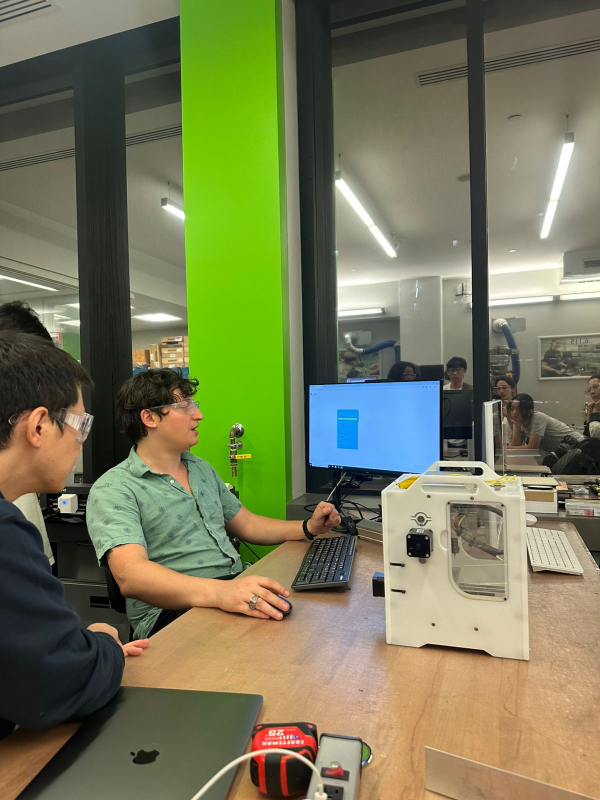
This week focuses on the fundamentals of digital fabrication: computer-aided design (CAD), computer-aided manufacturing (CAM), laser cutting, and vinyl cutting. We'll learn the complete workflow from design to finished parts.
This Week's Goals
- Master CAD fundamentals
Parametric design, constraints, and best practices - Laser cutting workflow
Design → CAM → cut → test → iterate - Vinyl cutting techniques
Vector graphics, weeding, application
Assignments
- Parametric construction kit
Design and fabricate a modular construction kit - Vinyl cutting project
Create a vinyl sticker or decal - Documentation
Document the complete design and fabrication process - Safety training
Complete laser cutter and vinyl cutter training
Tools & Materials
- CAD software — Fusion 360, Onshape, or similar
- Laser cutter — Epilog or similar CO2 laser
- Vinyl cutter — Roland or similar plotter
- Materials — Cardboard, acrylic, vinyl sheets
Training Documentation
Comprehensive training notes and media from laser cutter and vinyl cutter sessions.
Laser Cutter Training
Focusing Process
- Focus view follows the laser beam
- Use zoom in/zoom out to get better view
- Press Z, the number with checkmark shows how much to move
- Use focusing stick until it just hits the edge of the material
- Bed moves during focusing process
Cutting Process
- Control P to print, use max power with fast speed
- Go to universal program for cutting
- Turn on power for air compressor
- Press green button to start cutting
Vinyl Cutter Training
Software Setup
- Use Chrome browser
- Go to modsproject.org
- Select Program → Open Program
- Choose Roland vinyl cutter: cut program
- Load image (SVG or PNG format)
- Change dimensions with DPI settings
- For PNG: be careful with curves as it changes pixels
- Can invert to change where black areas are cut
- Set origin (defaults are usually fine)
- Blue lines = cut, red lines = rapids (knife lifts up)
Machine Setup
- Lever sets tension on drive wheels
- Clamp down at the end
- Wheel needs to be in white sections
- Press power (if just turned on)
- Select sheet and press enter
- Use arrow keys to move around
- Hold origin for new origin point
Connection & Starting
- Get device and connect properly
- Can change cut force but probably not necessary
- Send file to cutter
Weeding Process
- Weed early - pick out pieces you don't want
- Fold vinyl over itself, don't go straight up
- Use tweezers for precision
- Use transfer paper to lay front of vinyl on transfer paper
- Peel backing of vinyl off carefully
- Don't just plop things down to avoid air bubbles
- Use squeegee as you lay down to prevent air bubbles
- Consider sticker vs stencil applications
Useful Documentation
Additional resources and guides from Anthony Pennes for laser cutting, vinyl cutting, and image compression workflows.
Anthony's HTMA Guides
Comprehensive guides covering essential digital fabrication techniques, parameter optimization, and workflow best practices.
Image Compression Guide
Essential techniques for optimizing image file sizes, setting up batch processing tools, and maintaining repository efficiency.
📖 View GuideLaser Cutting Guide
Complete laser cutting workflow including safety, parameter optimization, joint design, and troubleshooting techniques.
📖 View GuideVinyl Cutting Guide
Detailed vinyl cutting techniques, software setup, machine operation, and weeding processes for professional results.
📖 View GuideNote: These guides were created by Anthony Pennes and are maintained as supplementary resources for the HTMAA course. View original Slack message for context.
Class Week Resources
Official course resources for project management, computer cutting, and Git recitation materials.
Lecture Information
-
Project Management - MIT Academy
Comprehensive guide to project management including file synchronization, version control (Git, GitHub, GitLab), web development, and documentation workflows. Covers essential tools for managing digital fabrication projects.
-
Computer Cutting - MIT Academy
Complete resource for computer-controlled cutting including laser cutting, vinyl cutting, and other cutting technologies. Covers safety, machine operation, material selection, and design considerations.
Recitation Information
-
Hands-on Git tutorial covering version control fundamentals, repository management, collaboration workflows, and best practices for digital fabrication projects.
Laser Cutter Characterization Group Assignment
Systematic testing and documentation of laser cutter parameters for optimal cutting performance. Assignment started: September 11, 2025 Assignment completed: September 16, 2025
Machine Specifications
Available Lasers
- CO₂ Laser: 75W (large machine)
- CO₂ Laser: 60W (small machine)
- Fiber Laser: Back of lab
Test Parameters
- Rate: 500 pulses per inch (PPI)
- Power: 100%
- Speed: 30% (increased by 2.5% each test)
Laser Cutter System Details
Universal Laser Systems CO2 Laser Specifications
Hardware & Software
- Laser System: Universal Laser Systems CO2 Laser
- Control Software: Universal Control Software
- Design Software: Inkscape for vector design and cutting
- File Transfer: Inkscape used to send cuts directly to laser
Print Settings & Color Coding
- Red Line (0.001"): Vector cut - full power cutting
- Blue Line (0.001"): Engraving - raster engraving
- Optimization: Used weak vector cut for engraving to save time
- Line Weight: 0.001" for both cutting and engraving operations
Workflow Note: The Universal Control Software provides precise control over laser parameters, while Inkscape serves as the design interface for creating and sending cutting jobs. The color-coded line system allows for efficient batch processing of both cutting and engraving operations in a single job.
Focus & Positioning
- Focus Point: Cut at the focal length (white part of the focusing stick)
- Kerf Measurement: Measure deltas between intended and actual cut dimensions
- Focus Accuracy: Critical for achieving clean, precise cuts
Joint Design & Clearance
Joint Type
Finger joint - interlocking design for structural connections
Clearance Definition
Size of the slot that provides tight enough fit for assembly
Material Considerations
Material choice significantly impacts joint quality and assembly precision
Key Learnings
- Speed increment of 2.5% provides systematic testing progression
- Focus accuracy is critical for dimensional precision
- Kerf measurement essential for compensating cut width in designs
- Material selection directly impacts joint quality and assembly success
- Systematic parameter testing reveals optimal settings for different materials
Results
Comprehensive analysis of kerf and clearance measurements from systematic laser cutter testing.
Interactive Data Analysis
View and interact with the complete dataset in Google Sheets:
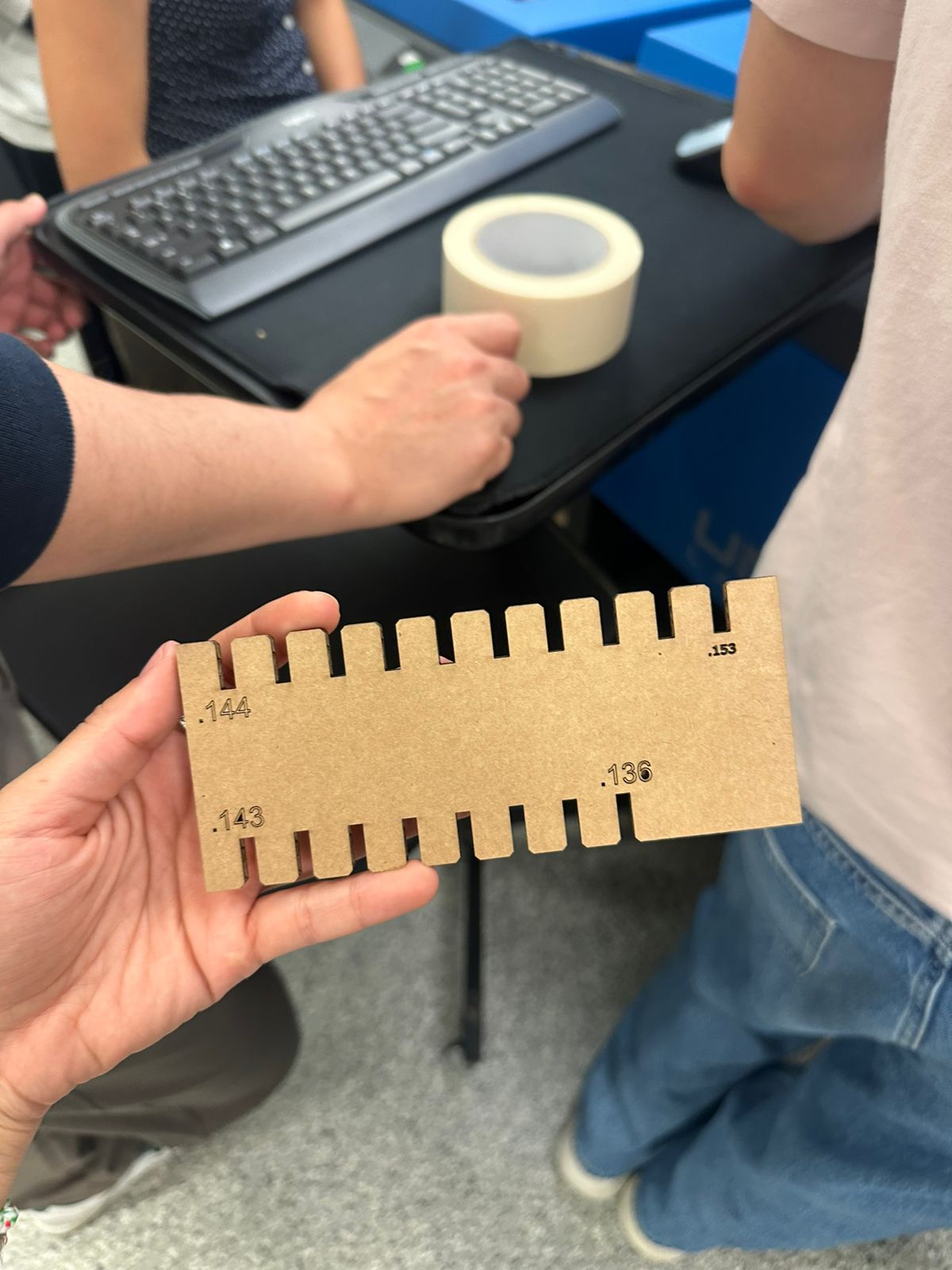
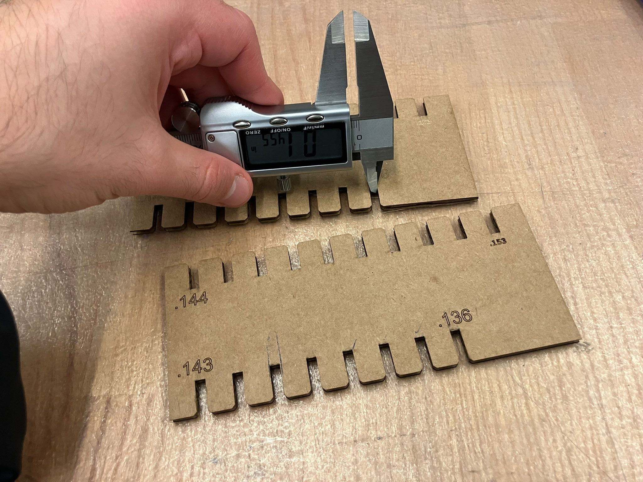
Measurement Methods
Systematic measurement approach for characterizing laser cutter kerf and joint clearance using precision calipers.
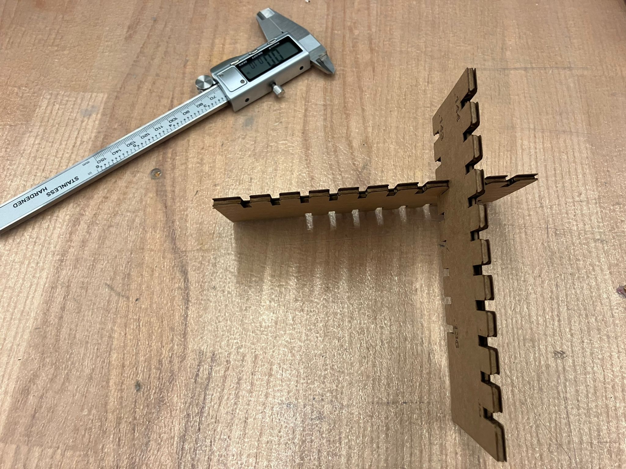
Peg and hole measurement setup
Top measurement view
Bottom measurement view
Measurement Protocol
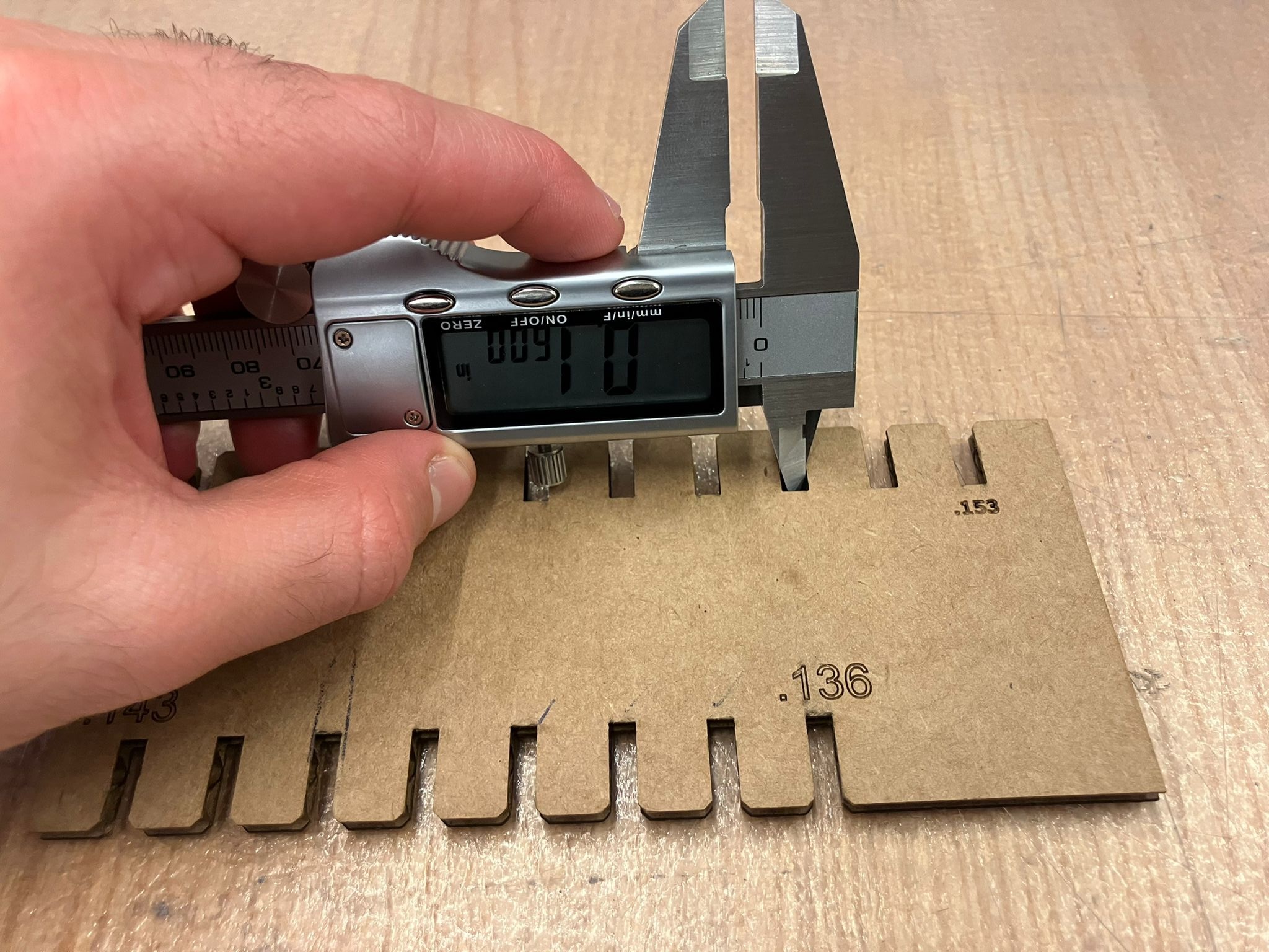
- Kerf Analysis: Three measurements were taken for each prescribed cut dimension on the joint gadget during laser cutter training
- Clearance Analysis: Three measurements were taken for both hole and peg dimensions
- Clearance Calculation: Clearance = Hole Size - Peg Size (negative values indicate interference fit)
- Statistical Analysis: Averages and standard deviations calculated for precision assessment
Kerf Concept Diagram
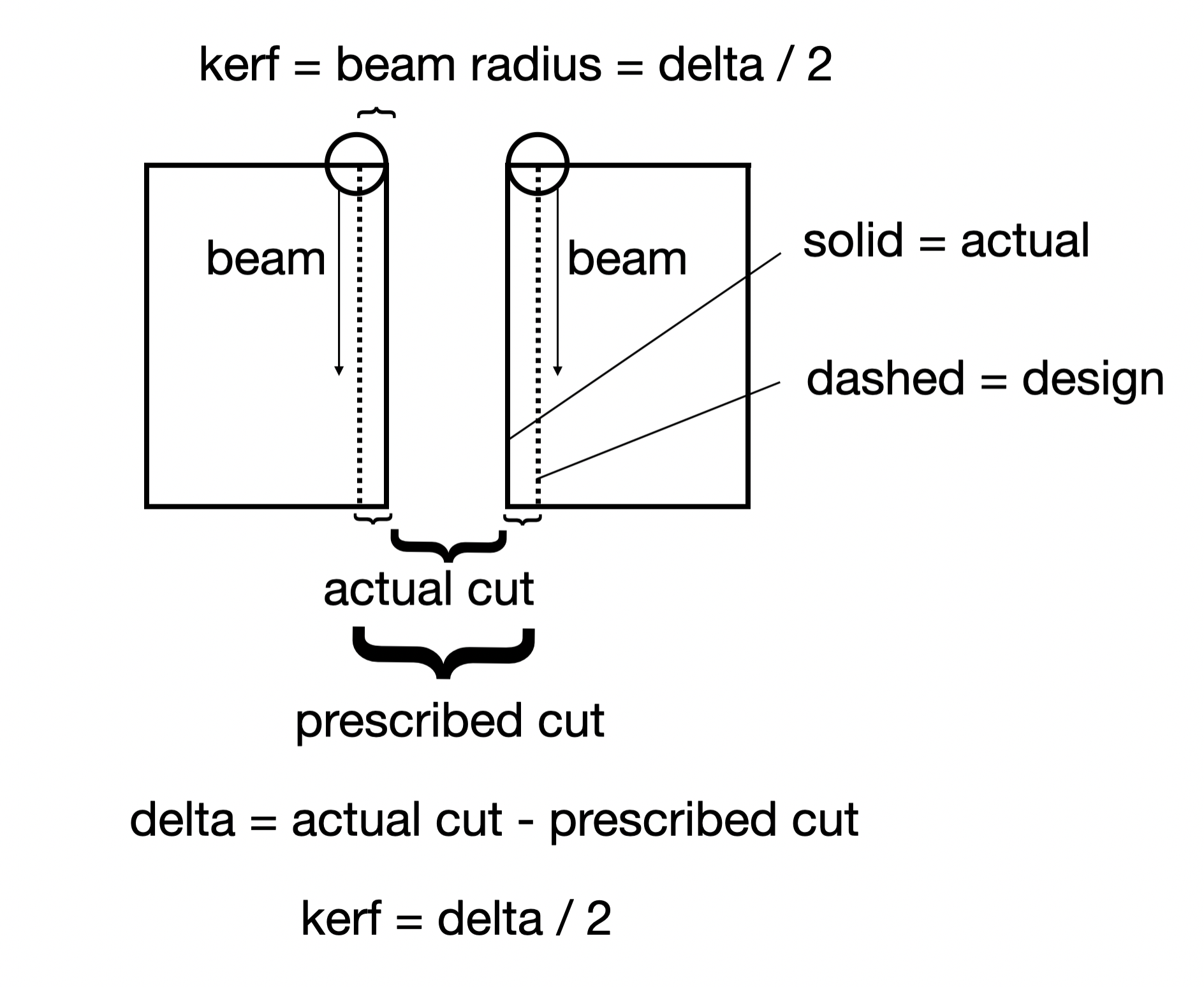
Kerf Definition: The width of material removed by the laser beam during cutting. Measured as the difference between prescribed cut dimensions and actual cut dimensions.
Kerf Analysis Results
| Prescribed Cut (in) | Actual Cut #1 (in) | Actual Cut #2 (in) | Actual Cut #3 (in) | Average (in) | Std Dev (in) | Avg Kerf (in) |
|---|---|---|---|---|---|---|
| 0.136 | 0.142 | 0.1405 | 0.1445 | 0.1423 | 0.0020 | 0.0032 |
| 0.137 | 0.142 | 0.1475 | 0.149 | 0.1462 | 0.0037 | 0.0046 |
| 0.138 | 0.148 | 0.1495 | 0.147 | 0.1482 | 0.0013 | 0.0051 |
| 0.139 | 0.146 | 0.146 | 0.1475 | 0.1465 | 0.0009 | 0.0038 |
| 0.143 | 0.155 | 0.1555 | 0.1545 | 0.1550 | 0.0005 | 0.0060 |
| 0.144 | 0.1535 | 0.153 | 0.15 | 0.1522 | 0.0019 | 0.0041 |
| 0.152 | 0.163 | 0.1655 | 0.165 | 0.1645 | 0.0013 | 0.0063 |
| 0.153 | 0.166 | 0.169 | 0.168 | 0.1677 | 0.0015 | 0.0073 |
Clearance Concept Diagram
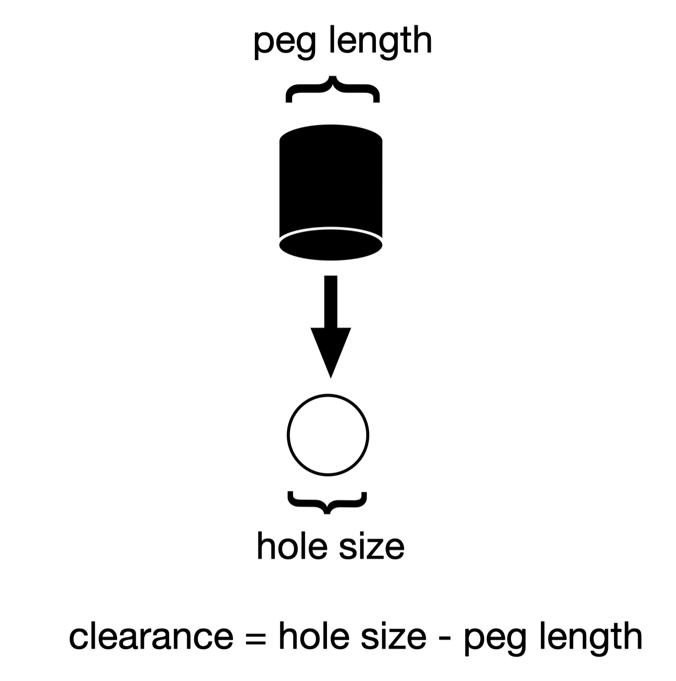
Clearance Definition: The dimensional difference between hole and peg sizes. Negative values indicate interference fit (hole smaller than peg), while positive values indicate clearance fit.
Clearance Analysis Results
| Measurement | Sample #1 (in) | Sample #2 (in) | Sample #3 (in) | Average (in) | Std Dev (in) |
|---|---|---|---|---|---|
| Peg Size | 0.1505 | 0.1535 | 0.1505 | 0.1515 | 0.0017 |
| Hole Size | 0.156 | 0.1575 | 0.1545 | 0.1560 | 0.0015 |
| Clearance | -0.0055 | -0.004 | -0.004 | -0.0045 | 0.0009 |
Key Findings
0.0049 inches (4.9 thousandths)
-0.0045 inches (interference fit)
±0.0017 inches (high precision)
±0.0009 inches (very consistent)
Parametric Construction Kit Individual Assignment: 3D Parametric Design
Design and fabricate a modular construction kit using laser cutting and vinyl cutting techniques. Assignment started: September 10, 2025. Assignment completed: September 15, 2025
Preparation & Planning
Initial research and clarification discussions with instructors and classmates to understand assignment requirements and technical constraints.
Key Clarifications
Technical Insights
Acknowledgments
Special thanks to Erik Demaine for guidance on vinyl cutting crease patterns and fold differentiation techniques, and Anthony Pennes for clarifying assignment requirements, file formats, and material options. Their expertise was invaluable in understanding the technical constraints and design possibilities for this project.
Design Process
- Research and ideation for construction kit design
- Create parametric CAD model with adjustable parameters in Fusion 360
- Generate CAM toolpaths for laser cutting
- Test cut on cardboard to verify fit and function
- Iterate design based on test results
- Final cut on appropriate material
- Design and cut vinyl project (separate from construction kit)
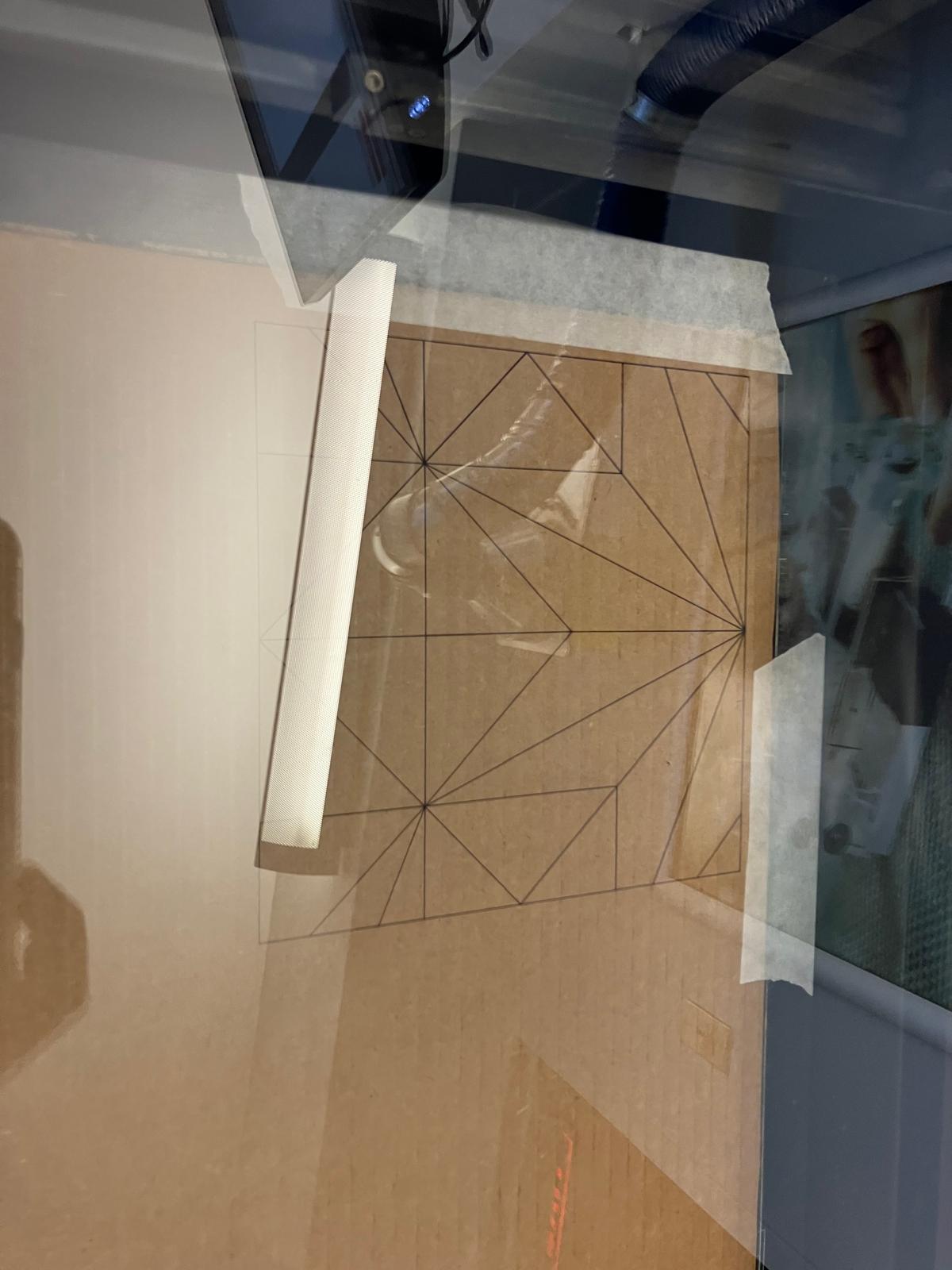
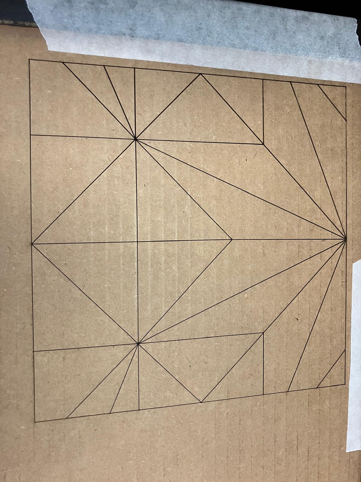
Hand‑folded Prototype Assembly
I hand‑folded the crease pattern to validate the assembly. The parts do come together when the folds are reasonably close to the intended lines. A second, refolded gadget produced a noticeably cleaner assembly.
Single Gadget
Double Gadget

Assembly Detail
Full Pattern Failure
We tried cutting the full crease pattern on one side. It failed when layers with opposite cuts overlapped and had to be push‑folded through during the final folding step — the piece broke.
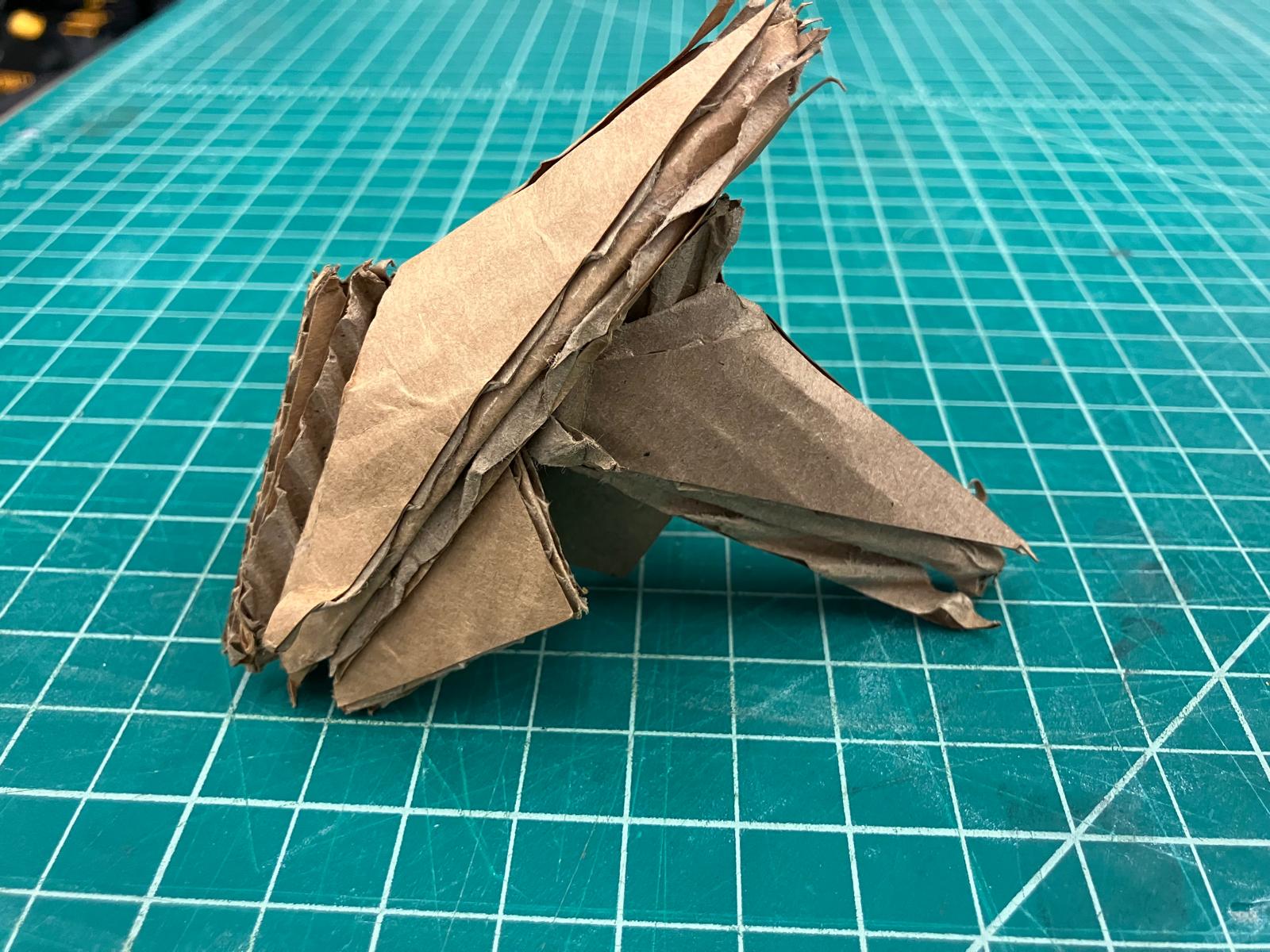
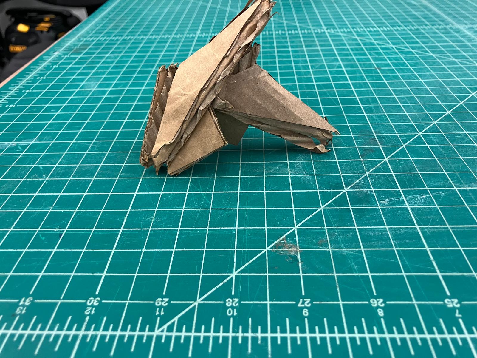
First Success Folded Single Gadget
First assembly of two gadgets. Folds were smooth after separating mountain and valley cuts onto opposite sides to avoid breaking during push‑folds over multiple layers. The shop cardboard was tight in the assembly pocket; thinner Amazon box cardboard folded by hand fit better. Next step: make the laser‑cut pattern more exact.
Cut Strategy Videos
Left to right: clear mountain cut, flip and cut the opposite side, clear valley cut.
Mountain vs Valley Sides
Measurements confirming mountain vs valley sides.
First Gadget Assembly
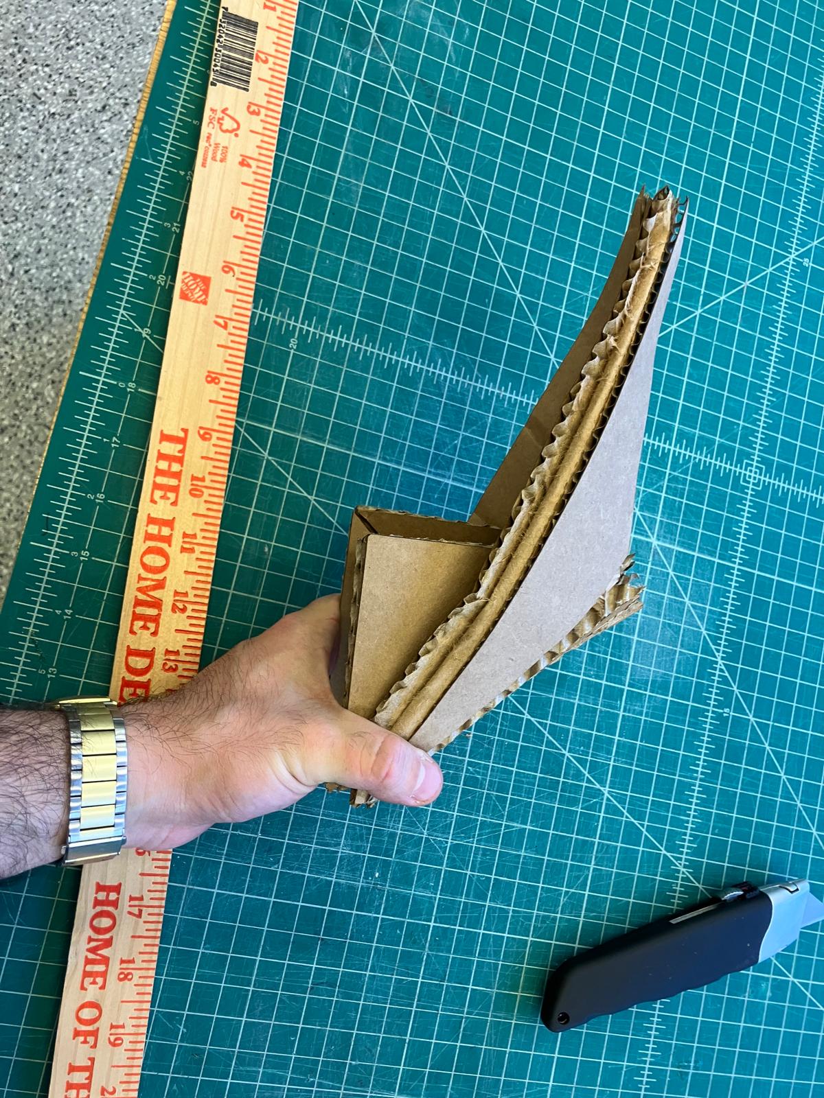
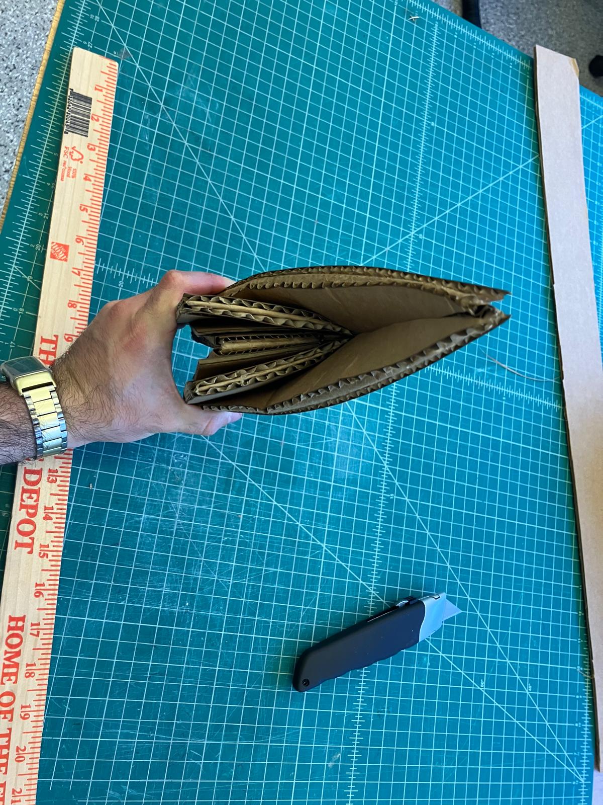
Side profile and insertion step demonstrating clean folds without tearing.
Double Gadget Cut Variations
Exploring double‑part strategies: sequential cuts, flips between sides, and opposite‑side cuts.
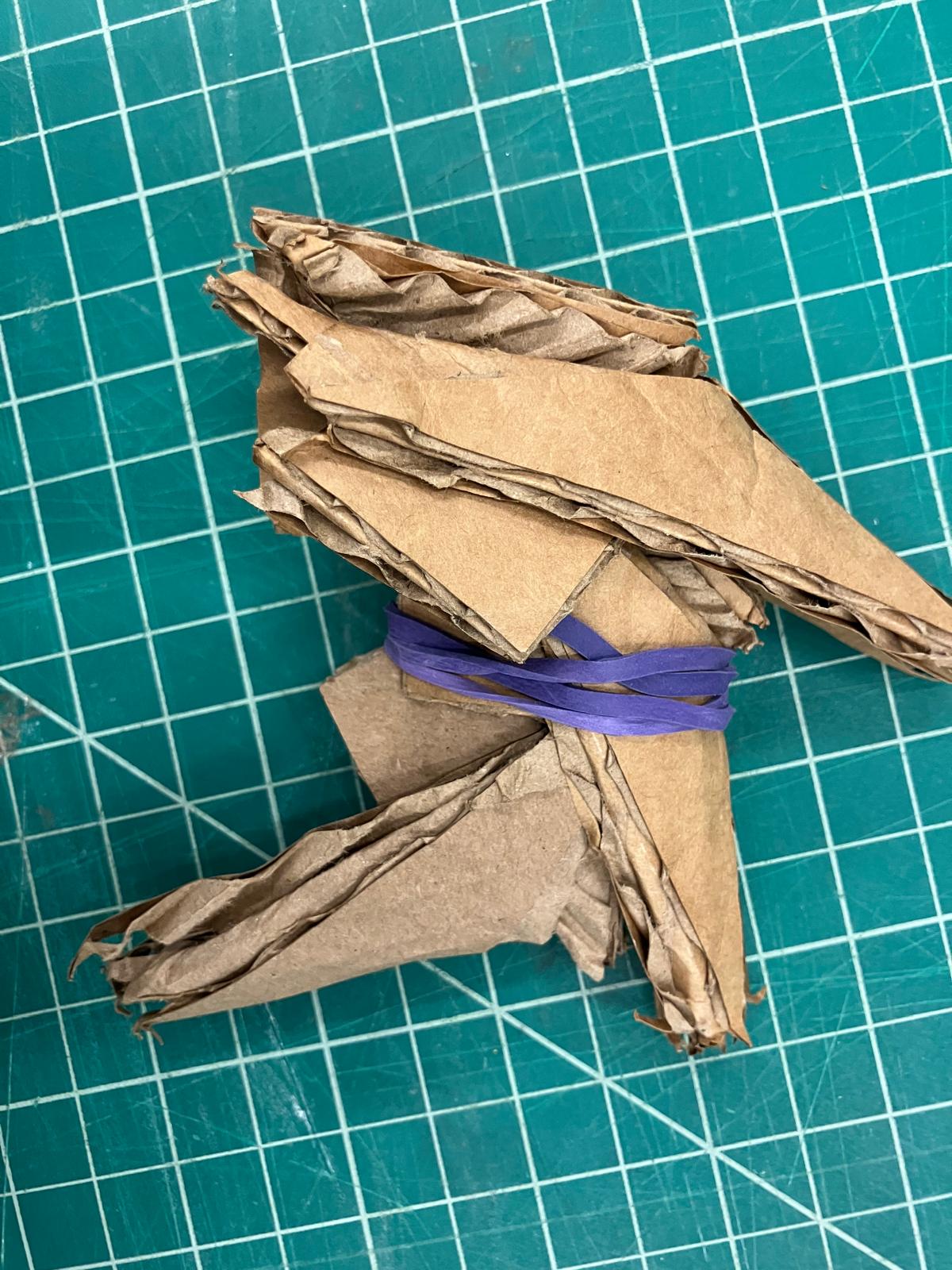
Double Gadget — Rubber Band Assist
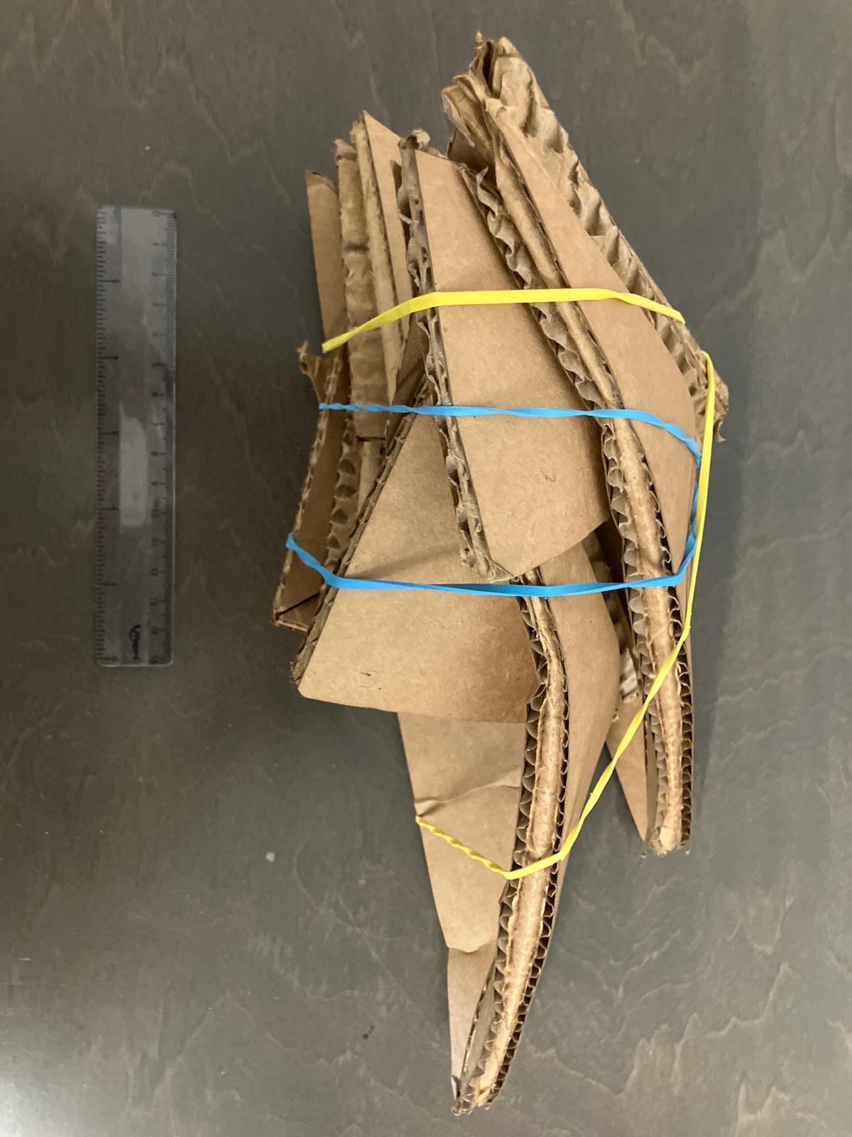
Temporary rubber band used to hold alignment while completing final folds.
First Success Assembly
Switched to thinner Amazon cardboard because the shop cardboard was too thick for the assembly pocket. The Amazon box folded by hand fit perfectly and assembled smoothly. Three gadgets worked with the thinner material. Rubber bands are just for compression — they assemble without them, though the bands make it easier to keep them as one unit during insertion into the next gadget.
Quadruple Cut Strategy
Scaling up to quadruple cuts: sequential cuts, flips between sides, and opposite-side cutting strategies.
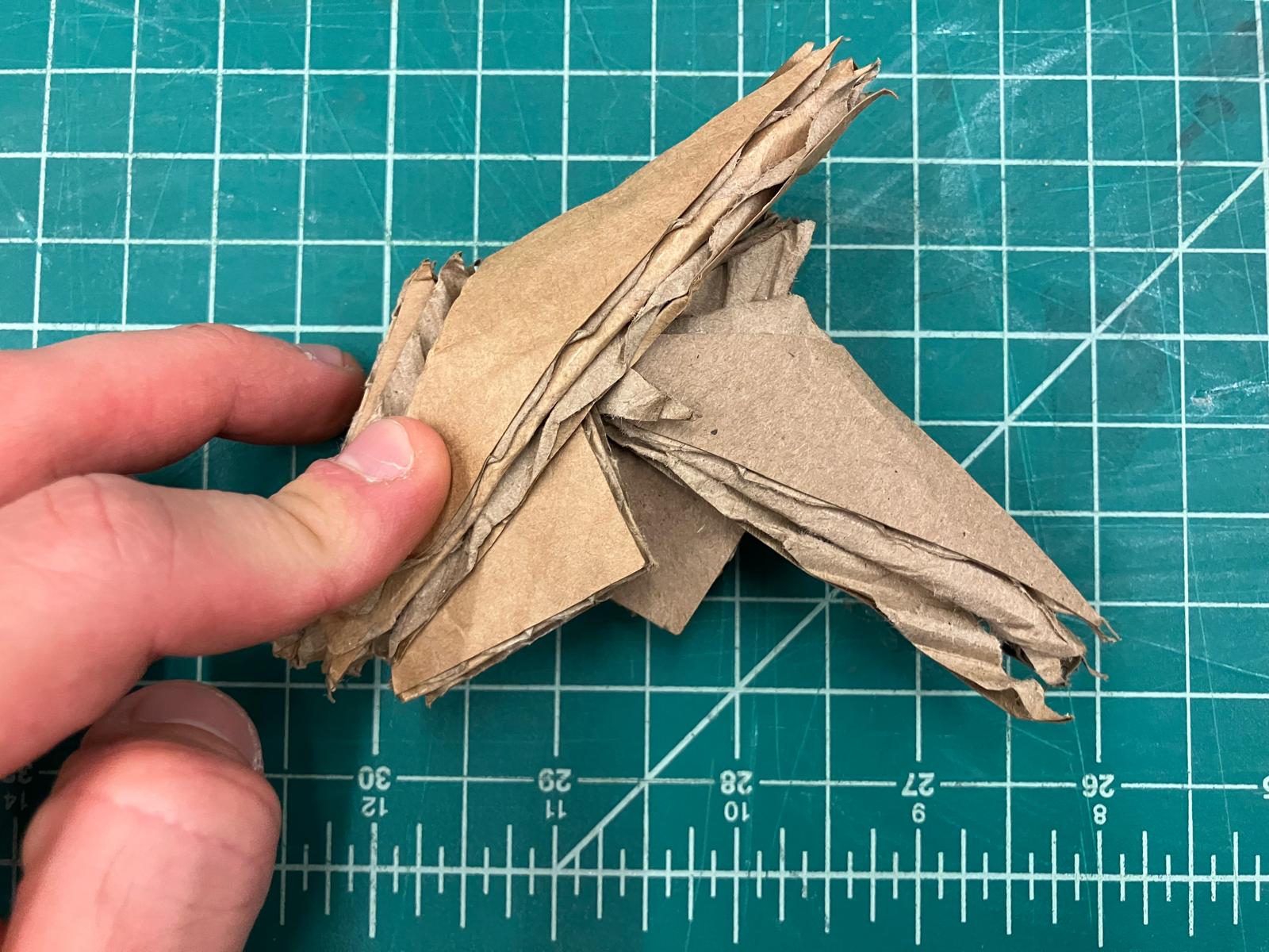
Double Gadget — Amazon Cardboard (No Support)
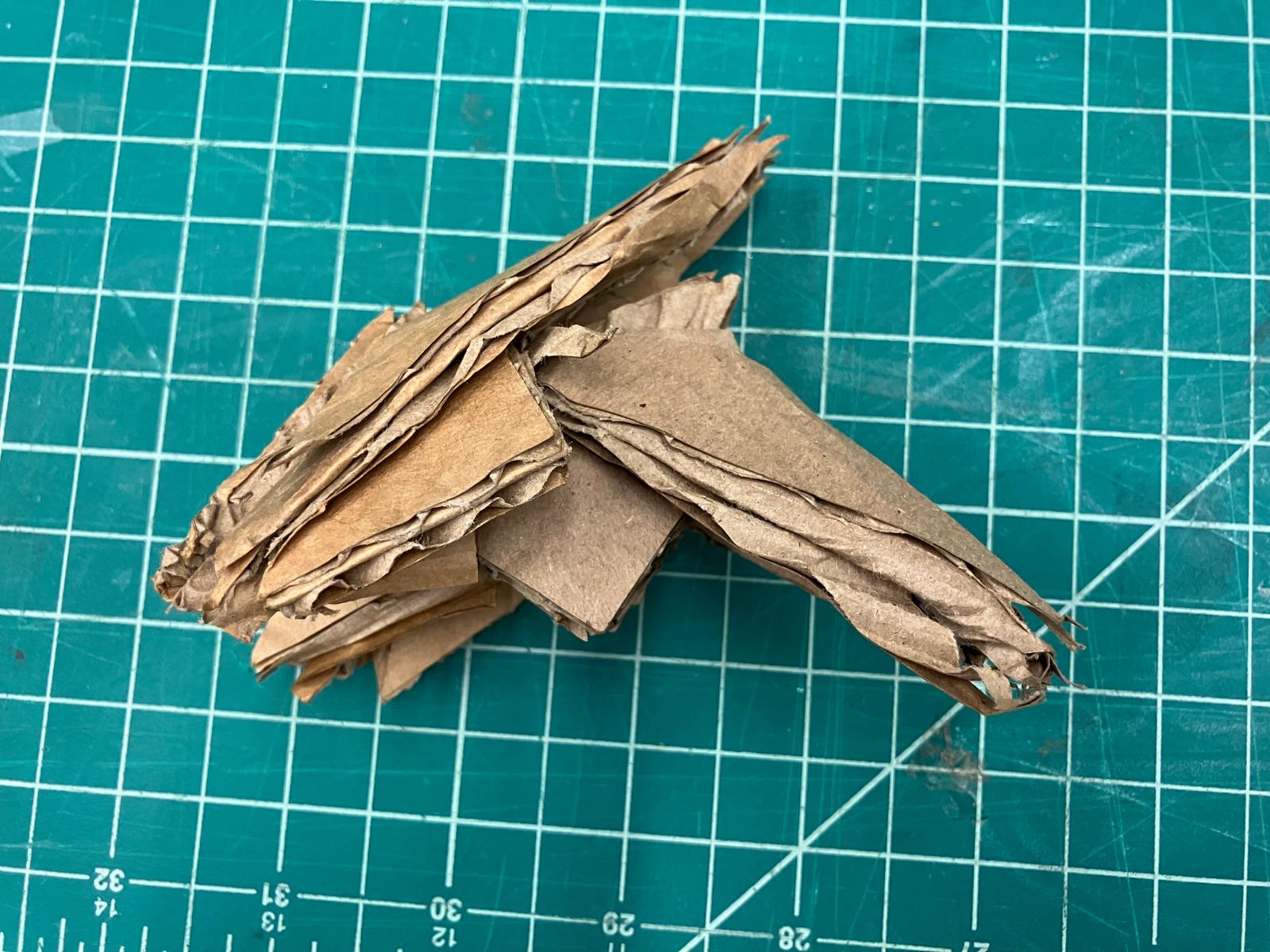
Three views of the double gadget assembled with Amazon cardboard, showing clean folds and proper fit.
Assembly Process with Support
Assembly sequence showing compression, support positioning, and insertion process for stable construction.
Triple Gadget — Final Assembly
The culmination: triple gadget assembly demonstrating successful scaling with Amazon cardboard and support techniques.
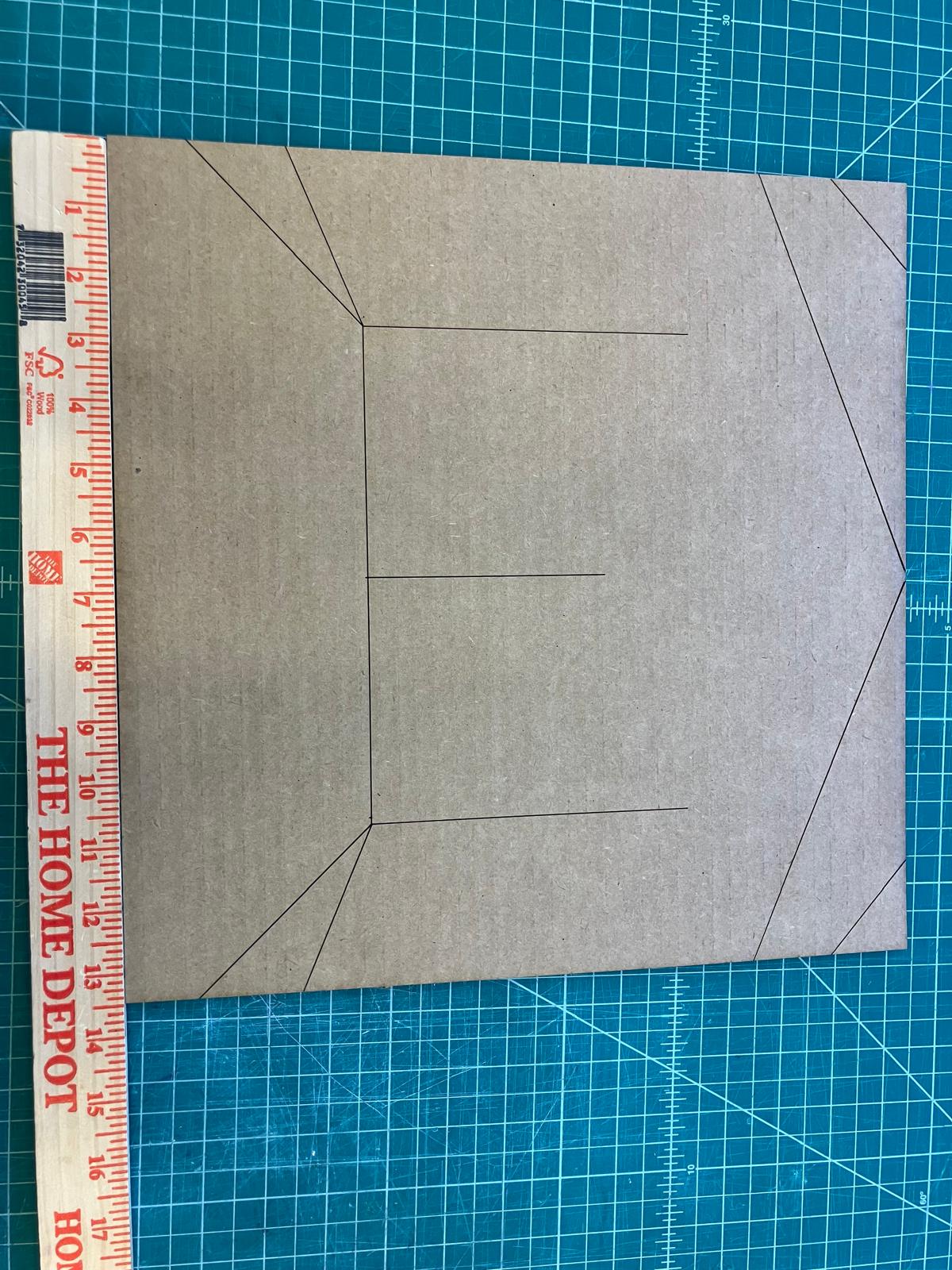
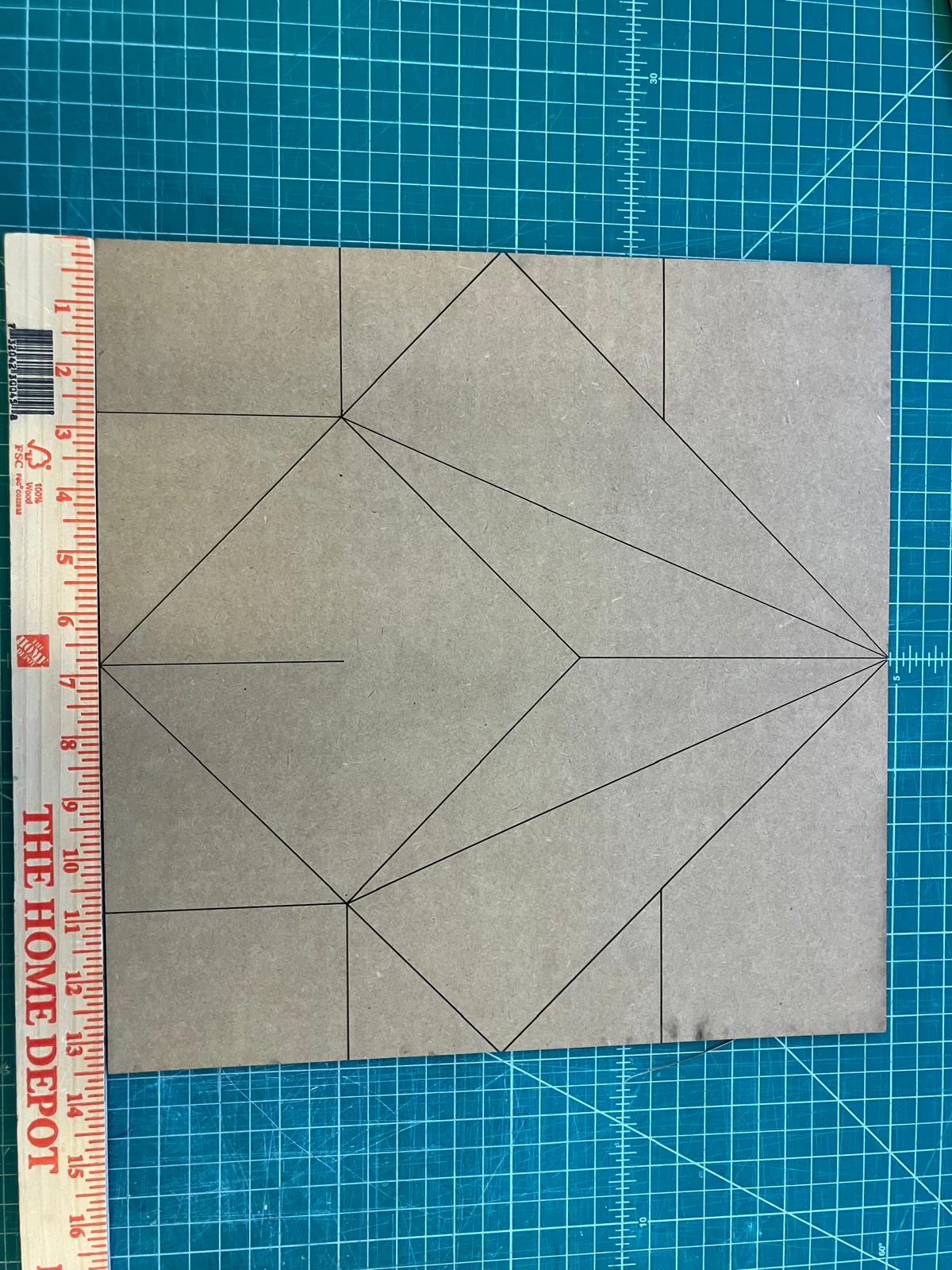
Further Refinements: Thick Origami
Applying thick‑origami concepts to avoid layer collisions and enable folding with real material thickness.
Guidance from Erik Demaine
From a discussion with Erik Demaine: double each crease into parallel offsets and open vertex regions as polygons to prevent collisions. A uniform spacing works for a first pass, but for correctness the spacing between the doubled creases should depend on how many layers lie between faces in the final folded state. I plan to estimate per‑crease layer counts from an unfolded model and adjust offsets accordingly.
Citation: Jason S. Ku and Erik D. Demaine, “Folding Flat Crease Patterns With Thick Materials”, Journal of Mechanisms and Robotics, 8(3), June 2016, pp. 031003‑1–6. View paper
Thickened Crease Patterns
- Estimate: double each crease with a uniform offset and add regular polygons at intersections.
- Exact: compute sector‑aware offset polygons at vertices using incident crease angles.
How the Estimate Works
    Input: crease segments with mountain/valley labels; sheet size S; target thickness t
    offset = t / S  (or a chosen fraction)
    for each crease c:
      draw two lines parallel to c at ±offset
    for each vertex (intersection of original creases):
      place a small regular polygon (e.g., octagon) centered at the vertex
    Output: doubled creases + vertex holes
How the Exact Method Works
    Input: crease lines; sheet size S; target thickness t
    offset = t / S
    for each crease c:
      compute unit direction v and normals n1,n2
      define two infinite offset lines at ±offset along n1/n2
    for each vertex:
      collect incident creases; sort by angle into cyclic order
      for each adjacent pair (i, j):
    pick the offset side that lies inside the angular sector
    intersect those two offset lines → one polygon vertex
      connect all vertices in order → convex vertex polygon
    trim faces/creases by polygons as needed
    Output: doubled creases + exact vertex polygons
Next Step — Layer‑Aware Offsets
Following Erik's advice, offsets should scale with the number of layers between faces in the folded state. Plan: estimate per‑crease layer counts and set per‑crease offset = k × thickness × layers(c), while keeping vertex polygons valid to avoid collisions.
Vinyl Cutter Individual Assignment: 2D Parametric Design
Design and cut vinyl stickers and stencils using the vinyl cutter. Assignment started: September 15, 2025 Assignment completed: September 15, 2025
Project Overview
Planned to vinyl cut lab logo stickers at first. Collected .png or .svg for each logo for the vinyl cutter software, and executing the complete workflow from cutting to final application. I hope to come back to the lab logos when there is less traffic on the vinyl cutter, I was more excited to see the fine detail of the vinyl cutter with the 2D parametric design at first!
Lab Logo Designs

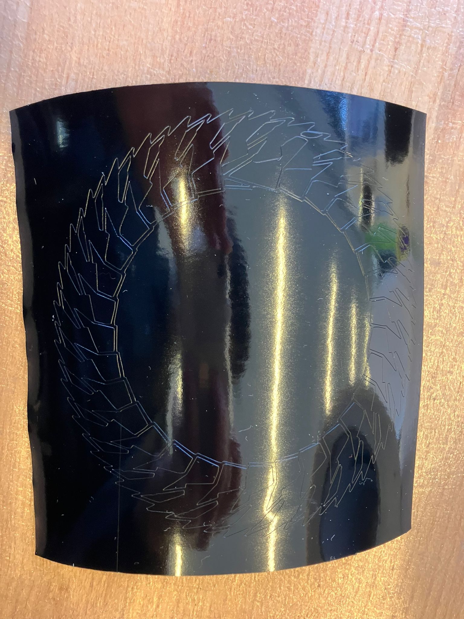
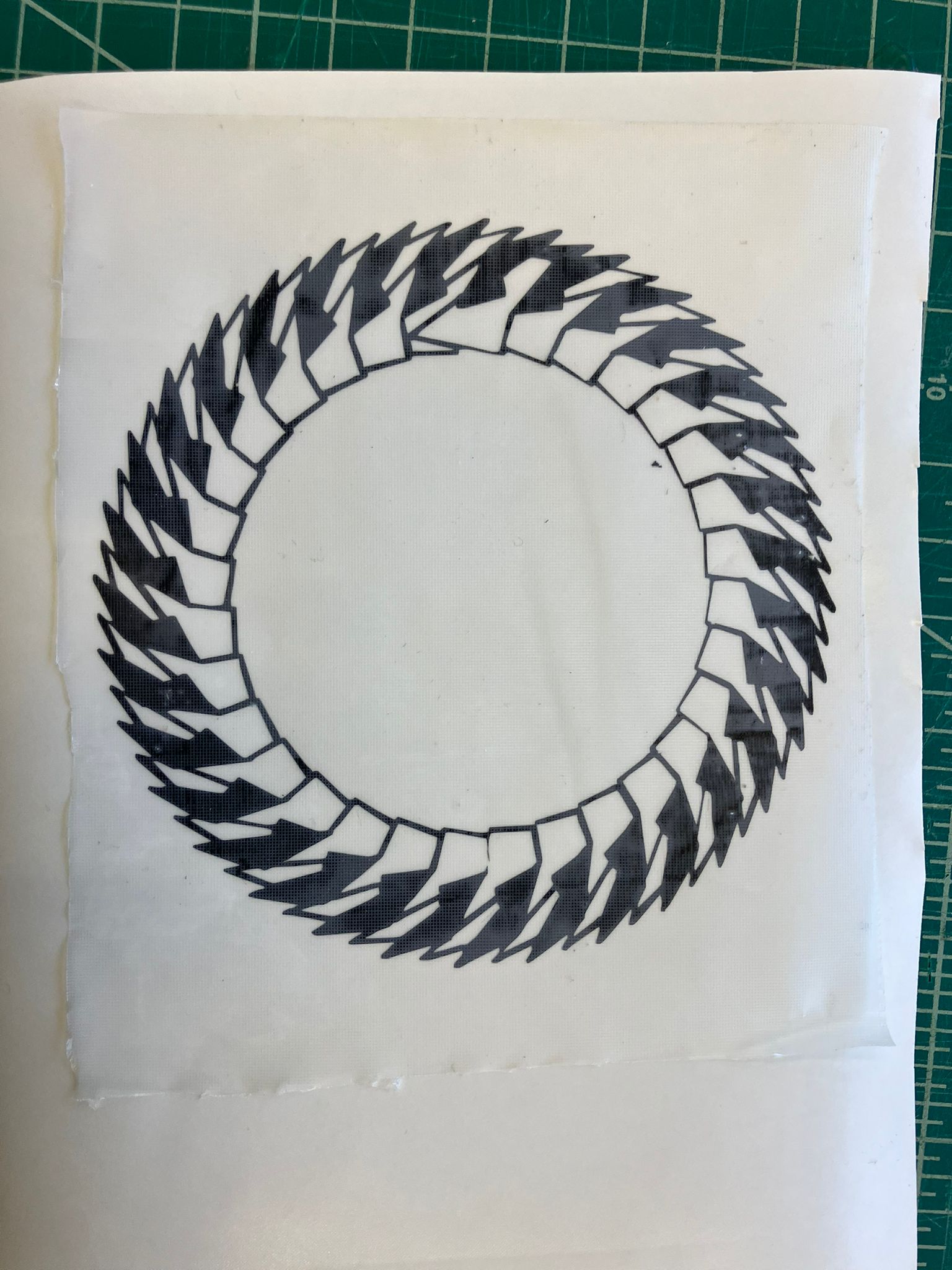
2D Parametric Sticker Design
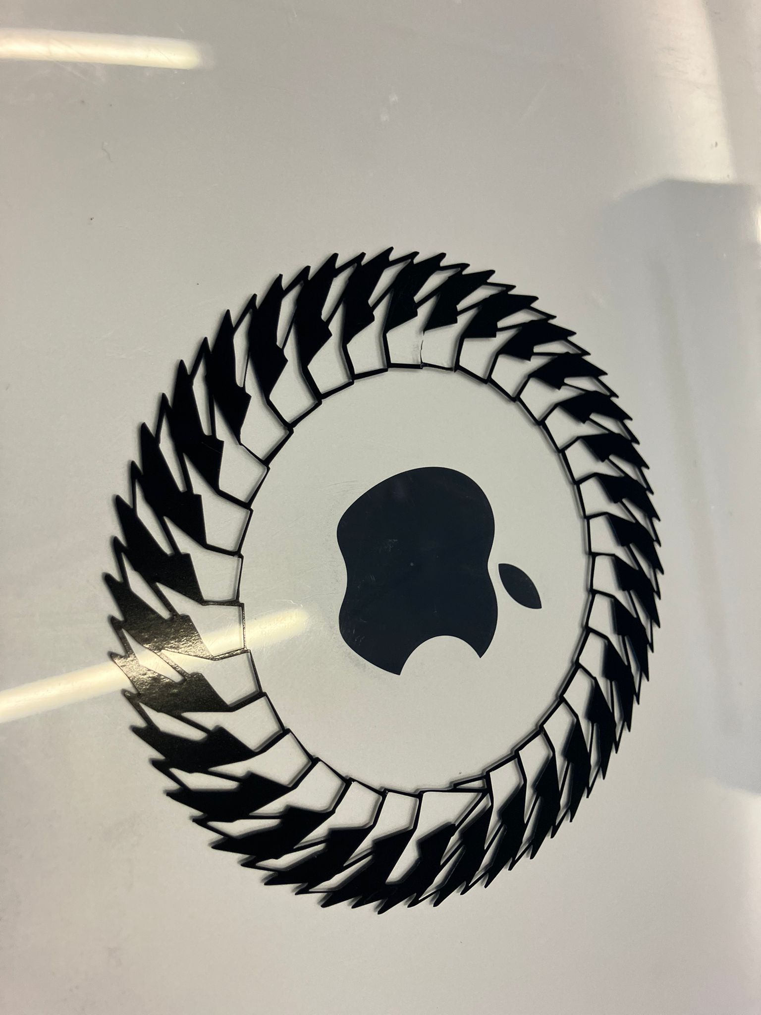
Used a parametric sticker design that can be infinitely customized through an interactive web application. The design demonstrates the power of parametric modeling in creating personalized vinyl stickers with adjustable parameters for size, complexity, and visual elements. The assignment demonstrated both successful execution and troubleshooting when equipment issues arose.

Interactive Design Generator
This web-based generator was created as a final project in 6.5310 last semester and was used to download a PNG of the default design shown above. Generate unlimited variations of this parametric design by adjusting parameters in real-time to create custom stickers for any application.
🎨 Generate Custom DesignsSuccessful Cut and Transfer
Complete workflow from vinyl cutting through final sticker application, demonstrating the full process from design to finished product.
Vinyl Cutting Process
Vinyl cutter in action, cutting the Gladyshev Lab logo design with precise blade control and proper tension settings.
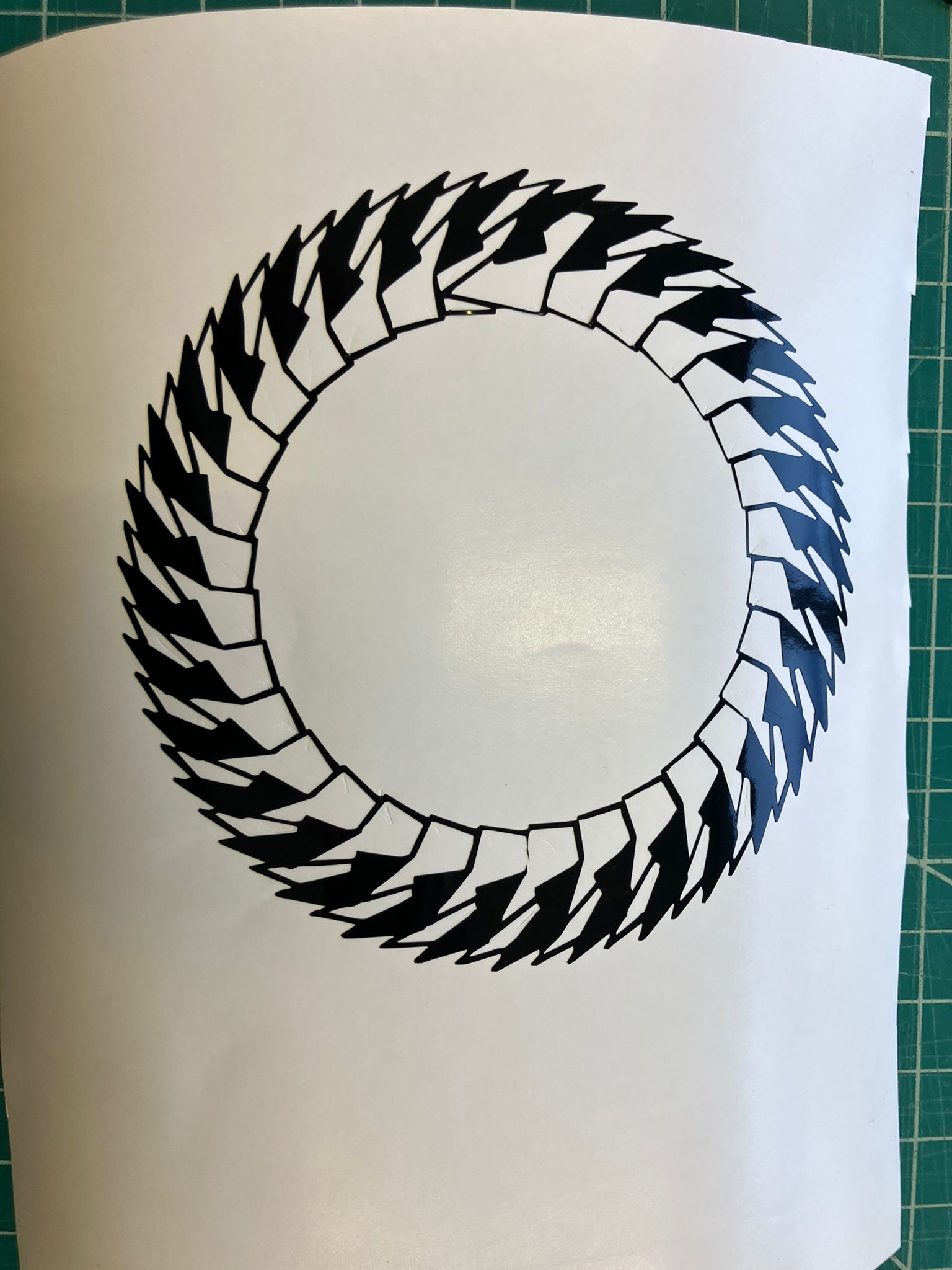
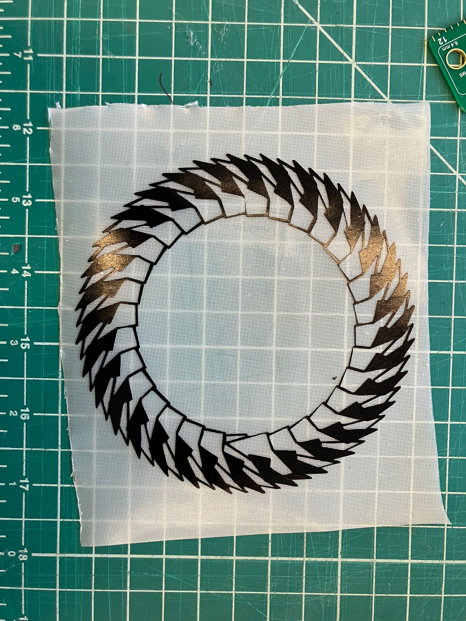
Completed Vinyl Cut
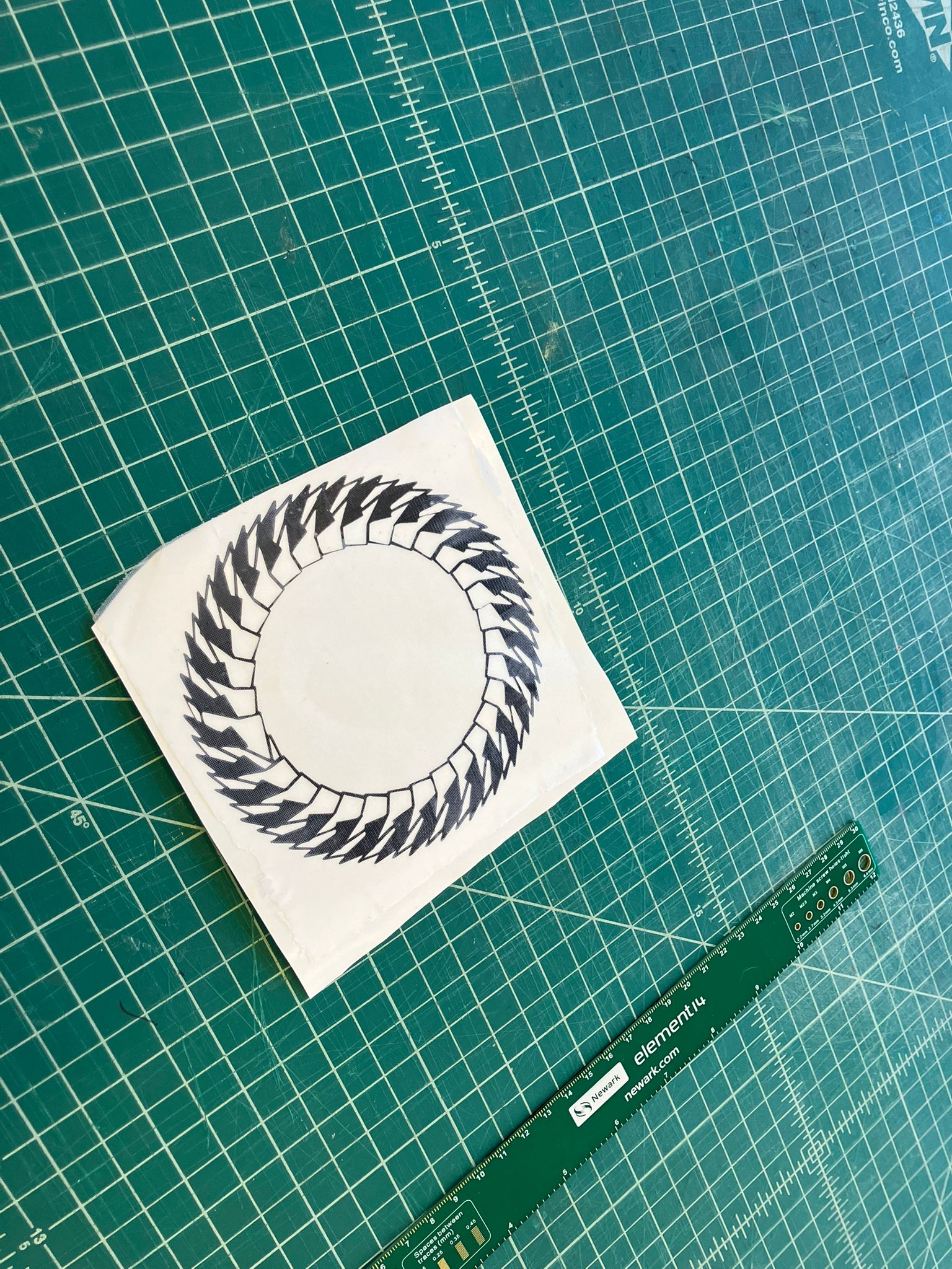
Clean vinyl cut showing precise cuts with proper registration and no tearing or incomplete cuts.
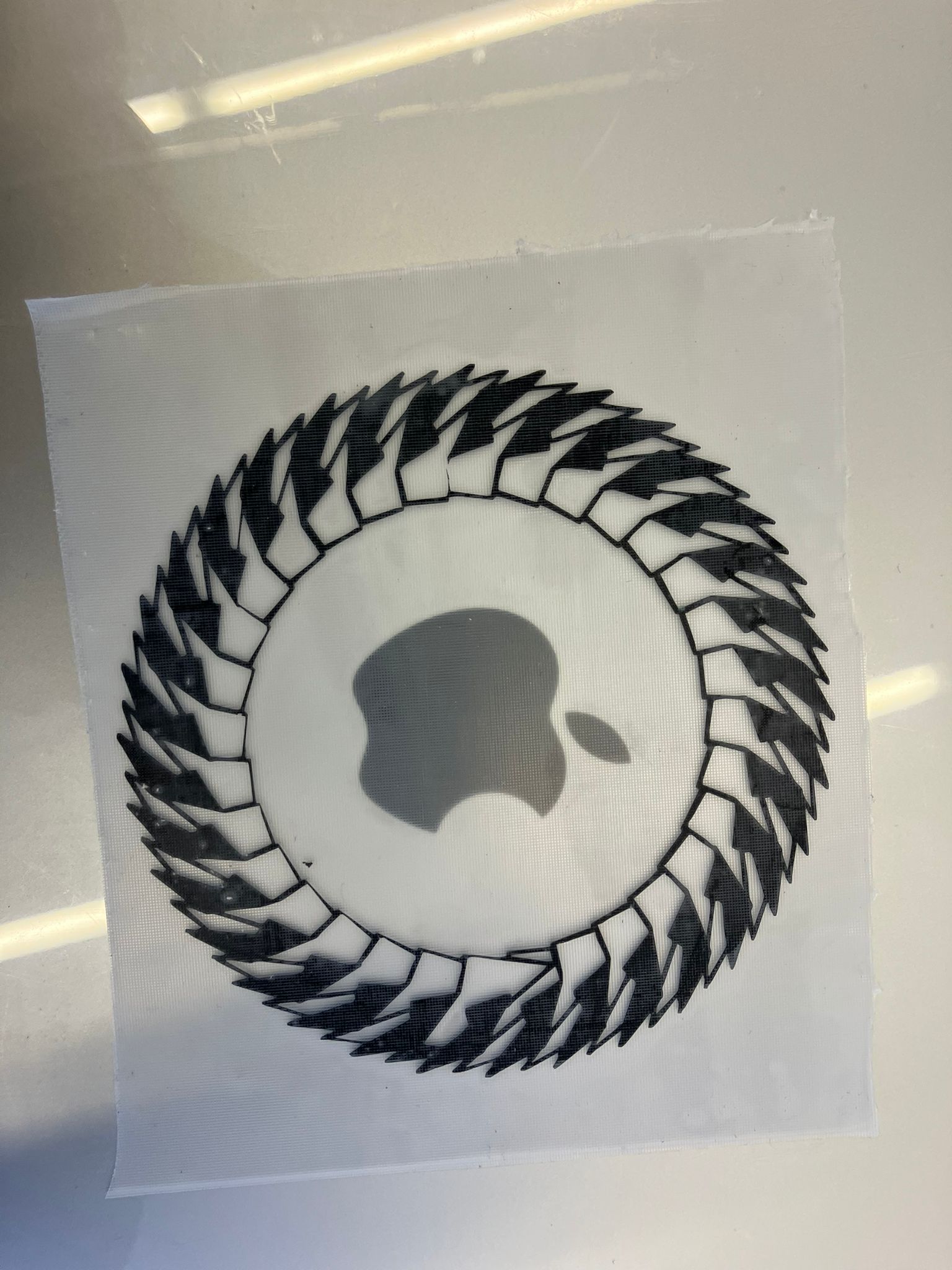
Weeding Process
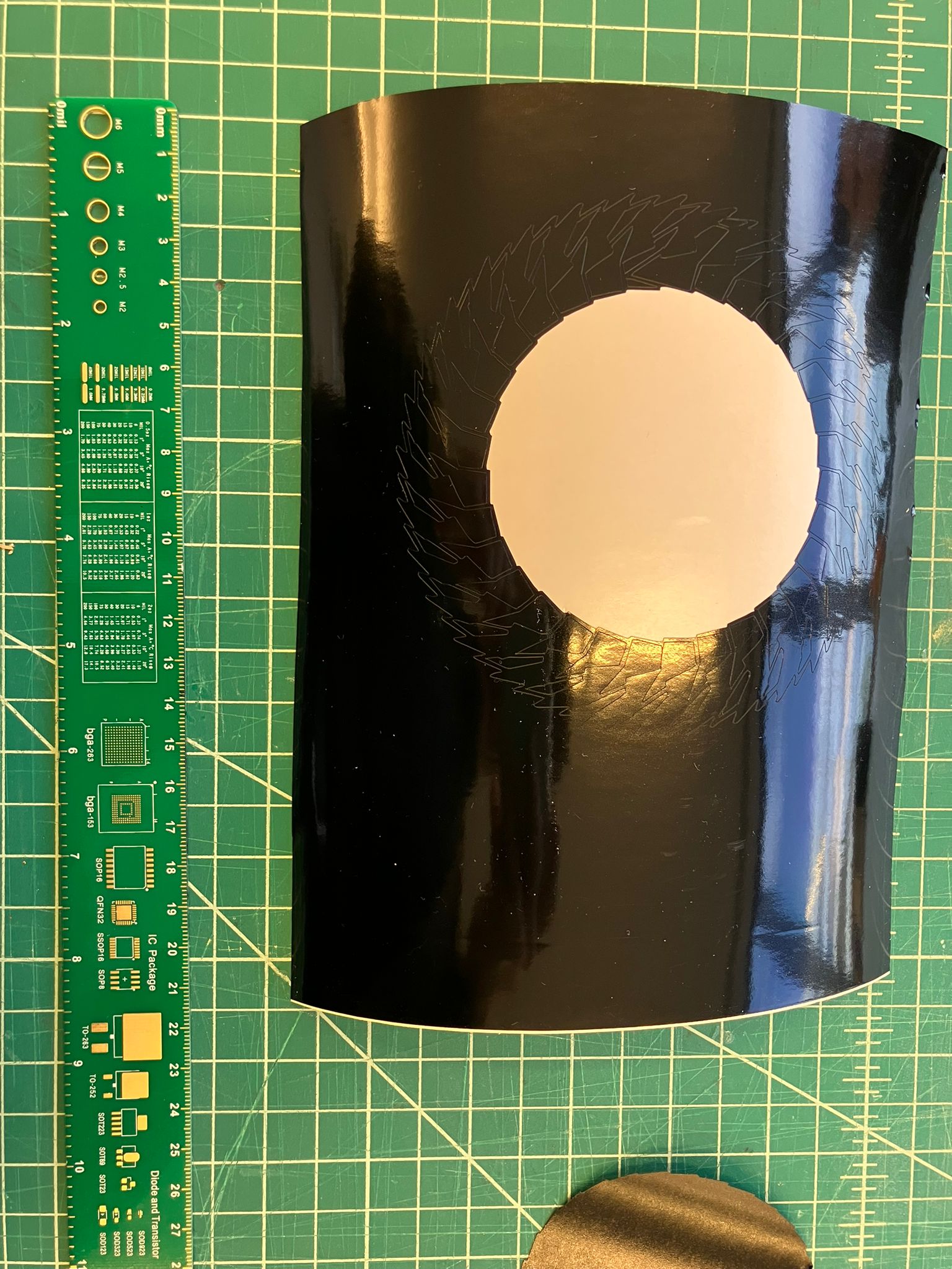
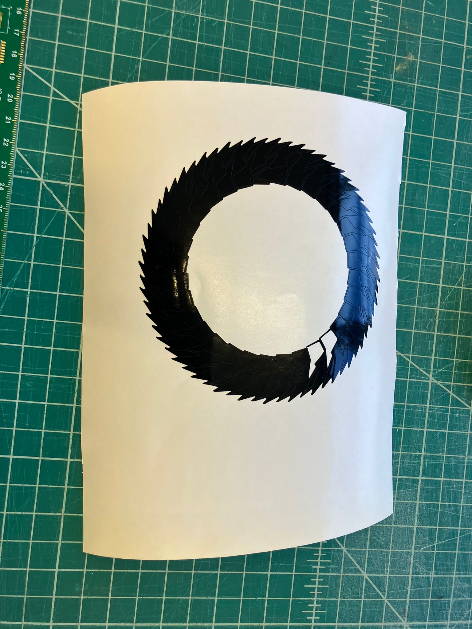
Systematic weeding process: starting from center, progressing through unwanted sections, and finishing with clean weeded vinyl ready for transfer.
Transfer Paper Application
Transfer paper application process: carefully applying transfer paper to hold vinyl design, then removing it to prepare for final application.
Vinyl Application Process
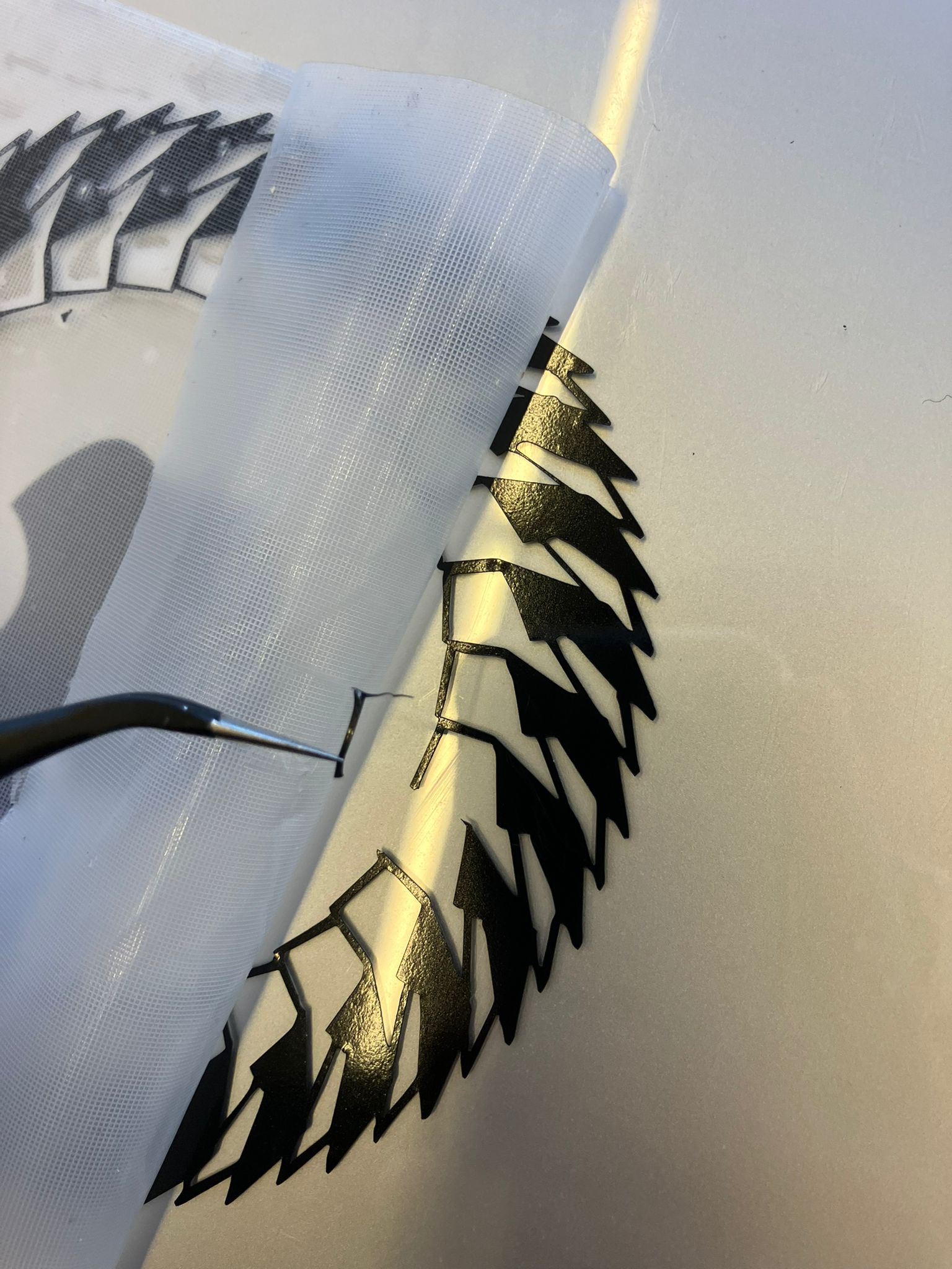
Final application steps: positioning vinyl on target surface, using tweezers for precise removal of the broken thin vinyl strip, and achieving clean final application.
Completed Takehome Sticker
Final result: applied laptop vinyl sticker and takehome vinyl sticker ready for use, demonstrating successful completion of the vinyl cutting workflow.
Motor Failure
Encountered and resolved a motor failure during the vinyl cutting process, demonstrating troubleshooting skills and equipment maintenance knowledge.
Motor Error Display
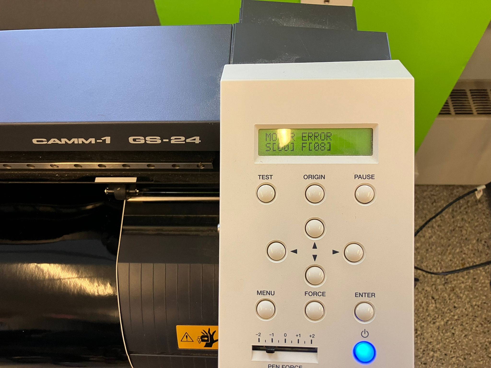
Vinyl cutter displaying motor error, indicating a mechanical issue that prevented normal operation.
Roll Failure Analysis
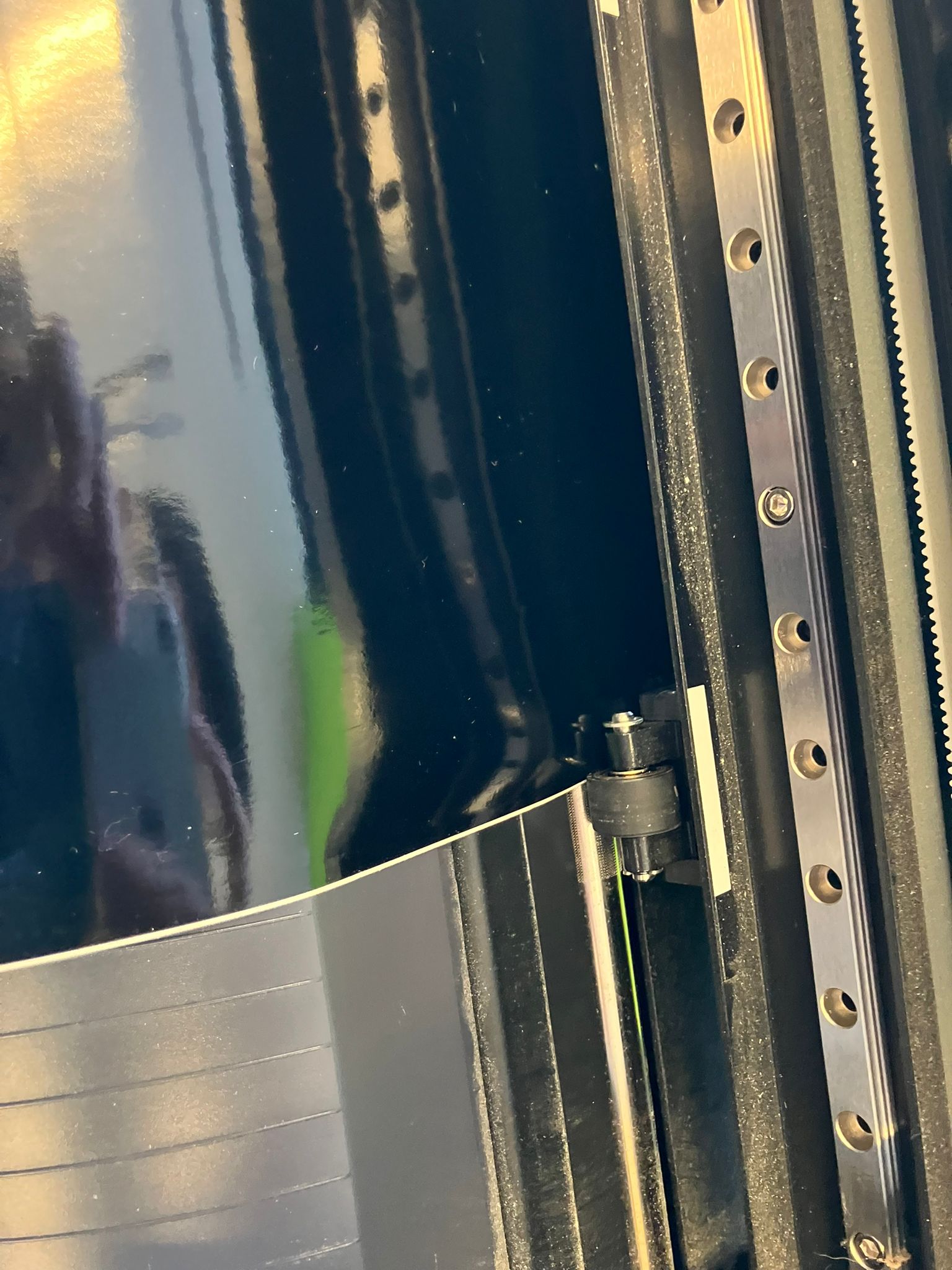
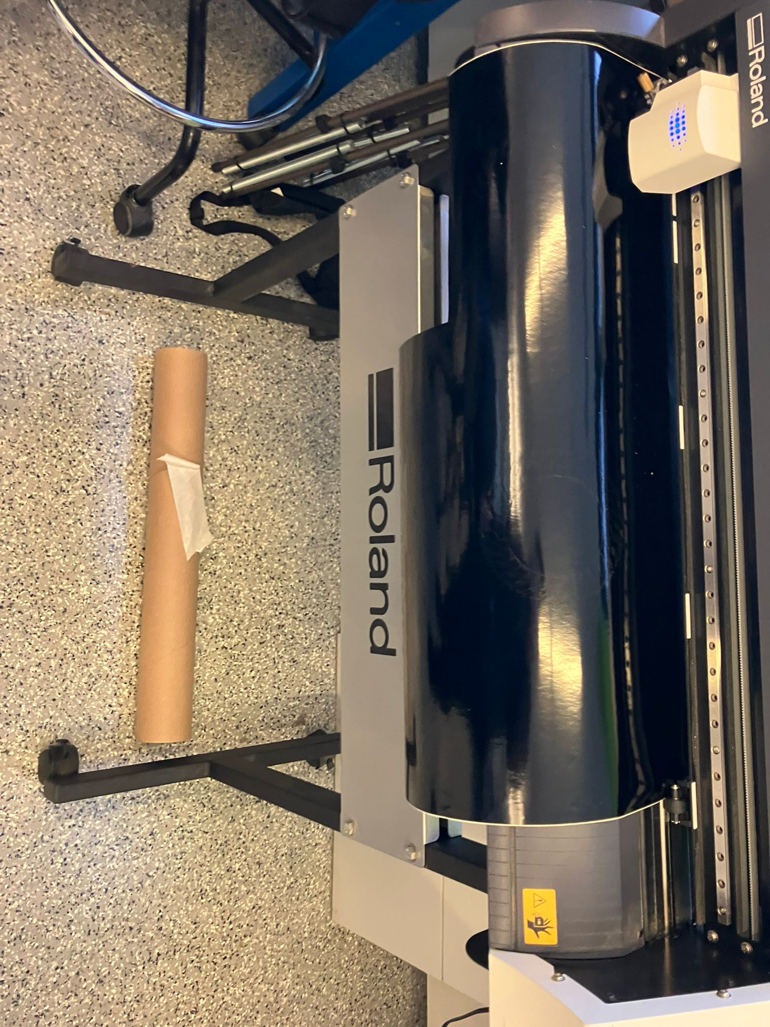
Side-by-side comparison showing the vinyl roll before and after the failure. The roll ran out of material and then fell, causing the vinyl to kink under the cutting wheel.
Troubleshooting Solution
Simple fix process:
- Turn off the vinyl cutter
- Remove tape from the fallen roll to get the weight off
- Readjust vinyl in between the wheels to ensure proper tension
- Start again (or load a new roll if needed)
This common issue occurs when the vinyl roll runs out or becomes misaligned, causing the cutting mechanism to fail. The solution involves proper material handling and machine setup.
Design Files
Download or view design files from this week's assignments.
Laser Cutter Design Files
CAD Files
SVG Files
Cut Files
Kerf and Clearance Design Files
Joint Test Files
Vinyl Cutter Design Files
Reflections & Learnings
Key insights and challenges encountered during this week.
Key Points
- Kerf compensation is critical for precise press-fit assemblies—systematic measurement revealed 0.0049" average with ±0.0017" variation
- Material selection matters: cardboard limitations (warping, structural weakness) require careful design considerations
- Iterative prototyping is essential—initial failures led to successful assembly through design refinement
- Parametric CAD design enables modular, scalable construction kits
- Vinyl cutting workflow requires attention to detail at each step for professional results
Laser Cutting Process Insights
- Understanding kerf and clearance measurements is critical for precise fits—the average kerf of 0.0049 inches with ±0.0017 inches standard deviation demonstrates the importance of systematic characterization.
- Material limitations became clear when working with cardboard: it's not ideal for complex patterns due to warping and structural weakness, requiring careful design considerations.
- The iterative design process from initial failure to successful assembly taught the value of prototyping and testing before committing to final designs.
- Parametric design using Fusion360 proved essential for creating modular construction kits that can be easily scaled and modified.
Vinyl Cutting Learnings
- Weeding techniques require patience and the right tools—proper preparation of the cutting surface and careful material handling significantly improve results.
- Understanding the relationship between cut depth, material thickness, and backing paper is crucial for successful vinyl cutting applications.
- The vinyl cutter workflow from design to application involves multiple steps that each require attention to detail for professional results.
Contributions
Acknowledgements for the help I received this week from my classmates and instructors.
Katrina Li - Training Documentation
This week's training was well-documented by Katrina Li, thank you!
Camron Blackburn - Website Review & Table of Contents Suggestion
Camron reviewed the website and provided valuable feedback on navigation and user experience. She suggested implementing a table of contents to make it easier for visitors to navigate through the different sections of the weekly documentation. This suggestion led to the creation of the sleek, organized table of contents that now appears on both Week 0 and Week 1 pages, significantly improving the overall user experience and accessibility of the documentation.
Mariam Fitaihi - Photos and Videos
Photos and videos of this week's training were taken by Mariam Fitaihi, thank you!
Anthony Pennes - Kerf and Clearance Design Files
Anthony Pennes provided the kerf and clearance design files (HTMAJointTest v0.f3d and HTMAJointTest.dxf) as part of the laser cutter training. These files were essential for understanding joint tolerances and clearance requirements when working with laser-cut materials.
Erik Demaine - Thick Origami Guidance
Erik reviewed my approach to folding thick materials and suggested using the Ku & Demaine thick‑origami method. He pointed me to the paper and emphasized that doubled creases should be spaced according to the number of layers between faces in the final fold. This feedback led me to implement two variants (estimate and exact) of thickened crease patterns and to plan a next step for layer‑aware offsets.
Jesse de Alva - Laser Cutting Assistance
Jesse helped me with laser cutting while figuring out how to do it, providing valuable guidance and support during the learning process. His assistance was crucial for understanding the laser cutting workflow and techniques.
Personal Notes - Laser Cutter Characterization
I took notes on the individual group assignment for characterizaing the laser cutter. :-)
Ethical AI Use
Transparent documentation of AI assistance used in this week's work, following course guidelines for ethical AI usage.
📋 General Guidelines: See General Commands for Cursor on the homepage for standard guidelines and commands used consistently throughout documentation development.
AI-Assisted Web Development in Cursor IDE
This week's webpage development, training documentation, and assignment preparation were assisted by Cursor AI. The AI helped with HTML/CSS implementation, content organization, and structuring technical documentation.
AI-Assisted Section Organization and Content Updates
Cursor AI assisted with organizing webpage sections, cleaning up HTML structure, and updating content for both week 0 and week 1 pages. The AI helped with code refactoring, section reorganization, and maintaining consistent styling across pages.
AI-Assisted Documentation and Link Integration
Cursor AI assisted with adding Anthony's HTMA guides to the Week 1 page, creating a new "Useful Documentation" section, and integrating external resource links with proper styling and organization.
AI-Assisted Week 1 Results Section Development
Cursor AI assisted with creating a comprehensive Results section for the Laser Cutter Characterization Group Assignment, including kerf and clearance analysis tables, measurement methodology documentation, concept diagrams, and downloadable resources. The AI helped integrate Google Sheets data, create professional data tables, and include the complete measurement analysis workflow.
AI-Assisted Week 1 Highlights Section Development
Cursor AI assisted with creating an interactive highlights section for Week 1, including visual improvements to the results display, clickable navigation links to detailed sections, table of contents integration, and enhanced user experience features. The AI helped implement hover effects, proper section linking, and visual hierarchy improvements for better navigation.
AI-Assisted Thick Origami Conversion
A separate chat was used to convert a flat crease pattern into a thick‑origami version following Ku & Demaine.
The AI doubled each crease into parallel offsets and generated vertex polygons (estimate = regular polygons; exact = sector‑aware polygons) and explained how to map desired thickness by setting OFFSET_FRAC = thickness / sheet_size.
AI-Assisted Repository Management and Content Organization
Cursor AI assisted with repository size management by breaking down large commits into smaller, manageable chunks under 10MB each. The AI helped organize media files into logical commits, added the Vinyl Cutter Individual Assignment section with proper styling and image sizing, and provided guidance on git workflow optimization to work within platform size limits.
AI-Assisted Vinyl Cutter Assignment Documentation
Cursor AI assisted with updating the vinyl cutter individual assignment section with comprehensive documentation including successful cut and transfer workflow, motor failure troubleshooting, and 2D parametric design integration. The AI helped structure the content with proper media organization, descriptive captions, and consistent styling throughout the section.
AI-Assisted Design Files Integration
Cursor AI assisted with adding a comprehensive Design Files section to the Week 1 page, including table of contents integration, organized file listings with download and view links, and contextual hyperlinks throughout the page for easy access to design assets. The AI helped structure the files by category (laser cutter CAD files, SVG patterns, vinyl cutter images) with appropriate styling.
AI-Assisted Design Files Integration for Laser Cutter Training
Cursor AI assisted with adding kerf and clearance design files from Anthony Pennes to the Week 1 Design Files section, creating a new subsubsection for joint test files, and properly attributing the contribution in the contributions section with links to both the Slack message and design files section.
AI-Assisted Layout Fixes and Section Structure
Cursor AI assisted with fixing layout and margin issues in week1.html, including resolving width inconsistencies and ensuring proper section structure. The AI helped identify and fix extra closing div tags that were causing content to appear outside their intended sections. The issue was resolved by manually removing the duplicate closing tags.
 This work is licensed under a
Creative Commons Attribution-NonCommercial-ShareAlike 4.0 International License
This work is licensed under a
Creative Commons Attribution-NonCommercial-ShareAlike 4.0 International License