
Week 3
3D Scanning and Printing
Week Highlights
Exploring the capabilities and limitations of additive manufacturing through hands-on design and printing experiments.
Table of Contents
Course Content
3D Printing & Scanning
Assignments & Projects
3D Scanning and Printing
This week focuses on additive manufacturing processes and 3D scanning technologies. We'll explore the differences between subtractive and additive processes, learn about various 3D printing materials and techniques, and understand the design constraints and capabilities of 3D printing systems.
This Week's Goals
- Test 3D printer design rules
Group assignment: Test design rules for available 3D printer(s) - Design additive-only object
Individual: Design and print object that cannot be made subtractively - 3D scan an object
Individual: Scan an object and optionally print it
Assignments
- Group Assignment
Test design rules for 3D printer(s) - Individual Assignment
Design, document, and 3D print object that could not be made subtractively - 3D Scanning
3D scan an object (and optionally print it)
Tools & Materials
- 3D Printers
FDM, SLA, SLS systems - Materials
PLA, PETG, ABS, specialty materials - Scanning Equipment
Photogrammetry, structured light, laser scanning - Software
Slicers, mesh editing, scanning software
3D Printing Processes
Understanding different additive manufacturing technologies and their applications.
Fused Deposition Modeling (FDM/FFF)
Most common desktop 3D printing method using thermoplastic filament
Stereolithography (SLA)
UV-cured resin printing for high detail and smooth surfaces
Selective Laser Sintering (SLS)
Powder-based printing for complex geometries without supports
Digital Light Processing (DLP)
Similar to SLA but uses digital light projection for faster printing
Binder Jetting
Powder and binder system for full-color printing
Material Jetting
Inkjet-style printing with multiple materials and colors
Materials
Common 3D printing materials and their properties.
PLA (Polylactic Acid)
Plant-based, biodegradable, easy to print, glass transition ~60°C, more brittle
PETG (Polyethylene Terephthalate Glycol)
Oil-based recyclable, glass transition ~80°C, tougher, better UV resistance
ABS (Acrylonitrile Butadiene Styrene)
Strong, impact-resistant, requires heated bed, more difficult to print
TPU (Thermoplastic Polyurethane)
Flexible material for rubber-like properties
PVA (Polyvinyl Alcohol)
Water-soluble support material
Specialty Materials
Wood-filled, metal-filled, carbon fiber, conductive materials
Design Rules for 3D Printing
Key constraints and guidelines for designing printable objects.
Overhangs & Supports
- Overhang angle
Typically 45° maximum without supports - Bridging
Short spans can be printed without supports - Support types
Tree, linear, and custom support structures
Geometry Constraints
- Wall thickness
Minimum thickness depends on nozzle size - Clearance
Gaps between moving parts need proper spacing - Infill patterns
Affects strength, weight, and print time
3D Scanning Methods
Various technologies for capturing 3D geometry of physical objects.
Photogrammetry
Multiple photos from different angles, processed with software like Meshroom, Polycam
Structured Light
Projects patterns onto object, captures deformation for 3D reconstruction
Laser Scanning
Time-of-flight or triangulation-based distance measurement
Stereo Vision
Two cameras for depth perception, similar to human vision
CT Scanning
X-ray tomography for internal structures and complex geometries
LIDAR
Light detection and ranging for large-scale scanning
3D Scanning Training
Comprehensive guide to 3D scanning techniques and best practices using structured light scanning systems.
Scanning Equipment
CrealityScan 4.1.2.8
Structured light 3D scanner with advanced scanning capabilities and user-friendly interface
Creality Ferret Pro
Professional-grade 3D scanner with high-resolution capture and precision scanning features
Step-by-Step Scanning Process
Initial Setup
- Create new project
Start with a fresh project in CrealityScan software - Select face scanner mode
Choose appropriate scanning mode for object type - Optimize lighting conditions
Ensure green indicator for optimal scanning conditions - Activate turntable
Enable automatic rotation for 360° scanning
Scanning Configuration
- Test optimal settings
Experiment with different configurations to find best results - Adjust fuse/resolution
Use default settings as starting point, then optimize - Position object correctly
Face away from windows and close shades for better results - Add reference objects
Include random items like booklets and USB dongles for better recognition
Post-Processing Workflow
Mesh Processing Steps
- Import to Meshmixer
Use Meshmixer for advanced mesh editing and cleanup - Delete unwanted geometry
Remove scanning artifacts, background elements, and noise - Fill holes and gaps
Repair incomplete areas using Meshmixer's hole-filling tools - Export final model
Save in appropriate format (STL, OBJ, PLY) for further use
Best Practices & Tips
Lighting Optimization
Ensure consistent, diffused lighting. Avoid direct sunlight and harsh shadows that can interfere with structured light scanning.
Object Preparation
Clean the object thoroughly. For dark or reflective surfaces, consider applying scanning spray or powder for better light reflection.
Reference Objects
Place small, recognizable objects around the main subject to help the scanner track movement and improve alignment accuracy.
Multiple Angles
Capture the object from multiple angles and positions to ensure complete coverage and minimize blind spots in the final mesh.
3D Printing Training
Comprehensive guide to 3D printing techniques, software configuration, and best practices for optimal print quality and efficiency.
Software & Hardware Configuration
PrusaSlicer 2.9.3
Advanced slicing software with comprehensive print settings and optimization tools
Prusament PLA
High-quality PLA filament with consistent properties and reliable printing characteristics
Purse CORE One HF0.4
0.4mm nozzle diameter for balanced detail and print speed
Build Volume
Maximum height: 10 inches - consider this constraint for tall prints
Plater Settings & Layer Configuration
Layer Height Optimization
- 0.2mm Default
Great balance between quality and speed - Lower Heights
Prettier surface finish, longer print times - Higher Heights
Faster printing, rougher surface finish - Speed vs Quality
Balance based on application requirements
Structural Considerations
- Wall Count
More walls = stronger parts, longer print time - Infill Density
Adjust based on strength requirements - Print Speed
Can often increase speed without quality loss - Vertical Shells
Critical for part strength and appearance
Advanced Print Settings
Surface Quality & Aesthetics
- Seams
Control where layer changes occur for better appearance - Fuzzy Skin
Adds texture to surfaces for improved grip or aesthetics - Surface Finish
Optimize for intended application and post-processing
Best Practices & Tips
Layer Height Strategy
Start with 0.2mm for most prints, reduce to 0.15mm for detailed parts, increase to 0.3mm for prototypes.
Speed Optimization
Test higher speeds gradually - many printers can handle faster speeds than default settings suggest.
Wall Configuration
Use 2-3 walls for most applications, increase for structural parts, decrease for decorative items.
Build Volume Awareness
Remember the 10-inch height limit when designing tall objects - consider splitting large prints.
File Formats
Common file formats used in 3D printing and scanning workflows.
3D Model Formats
- STL
Most common for 3D printing, triangular mesh - OBJ
Includes texture and color information - 3MF
Modern format with metadata and multiple objects - STEP
CAD exchange format with precise geometry
Printing Formats
- G-code
Machine instructions for 3D printer - PLY
Point cloud format for scanning - AMF
Additive Manufacturing Format with materials - VRML/X3D
Web-based 3D formats
Group Assignment: Test Design Rules
Test the design rules for your 3D printer(s) by creating a comprehensive test print that evaluates various design constraints and capabilities.
Download Detailed Slides: PDF Version | Keynote Version
Comprehensive presentation covering all design rule tests, results, and analysis methodology.
Supported Design Rule Tests
These tests evaluate features that should print reliably without additional support structures:
Overhang Testing (Supported)
- Test Result: Supported right angle overhang was successful with snug support (default)
We didn't need to try organic support for this test - Support Removal: Successfully removed support with pliers
Clean removal without damaging the part - Printer Used: Prusa Core One with white generic PLA
Standard settings provided good results
Clearance Testing
- Minimum Clearance: 0.2mm is the minimum clearance for an object to be separable
Tight fit, hard to rotate at this clearance - Optimal Clearance: Above or equal to 0.3mm is looser and more functional
Better for moving parts and assemblies - Non-functional: Below 0.2mm is not separable
Parts fuse together at this clearance
Helical Support Thickness Testing
- Too Fused: 0.48 revolutions/mm — too fused (28 revolutions over 60mm with 6mm diameter, 2mm thickness)
Parts become inseparable at this density - Optimal Range: 0.35 revolutions/mm — works (21 revolutions over 60mm with 6mm diameter, 2mm thickness)
Good balance between support and separability - Sweet Spot: Optimal exists between 0.35-0.48 revolutions/mm
Fine-tuning within this range for specific applications
Unsupported Design Rule Tests
These tests push the boundaries of what the printer can achieve without additional support structures:
Angle Testing (Unsupported)
- Minimum Angle: 20 degrees is minimum overhang angle (defined as degrees above right angle)
Below this angle, the print quality degrades significantly - Good Quality: 30 degrees and above are nicely formed
Reliable print quality at these angles - Poor Quality: 10 degrees and below result in spaghetti
Printer cannot maintain structural integrity at these angles
Overhang Testing (Unsupported)
- Maximum Distance: 2-3mm is maximum unsupported overhang distance before spaghetti
Beyond this distance, the print quality fails - Acceptable Range: Below 2-3mm is fine
Good print quality within this range - Failure Point: After 2-3mm becomes awkward
Structural integrity is compromised beyond this point
Bridging Testing
- Maximum Bridge: 18mm is maximum bridge size
Reliable bridging performance up to this length - Acceptable Performance: 20mm is actually not too bad
Slight degradation but still functional - Test Method: Horizontal unsupported spans
Evaluates printer's bridging capabilities without support
Wall Thickness Testing
- Minimum Thickness: 0.6mm is the minimum wall thickness that is sturdy
Below this thickness, walls are too fragile - Fragile Range: Thinner walls just break off if you touch them
Not suitable for functional parts - Design Implication: Use 0.6mm+ for structural elements
Critical for load-bearing applications
Dimensional Accuracy Testing
- Outer Distance: 20.05mm measured (one offset from 20mm design)
0.05mm offset in outer dimensions - Inner Distance: 9.90mm measured (twice offset from 10mm design)
0.10mm total offset in inner dimensions - Height Variation: Dimensions actually slightly differ as a function of height
Z-axis accuracy varies with print height
Anisotropy/Orientation Testing
- Quantification Method: Use filament width (w, XY) and layer height (h, Z) for geometric approximation
A ≈ w/h where A > 1 indicates anisotropy - Unsupported Results: w=730, h=545, A=730/545=1.339
Significant anisotropy in unsupported prints - Supported Results: w=20.11, h=20.16, A=20.11/20.16=0.998
Much more isotropic with proper support
Surface Finish Testing
- Layer Visibility: With default surface finish settings, layers are clearly visible
Further optimization necessary for smoothing - Nozzle Tracking: Can see the track of the nozzle during step height process
Step height can be adjusted and tuned for curvature needed - Roundedness Limitation: Limited roundedness, flat at the top
Can be adjusted from the step height settings
Infill Testing
- Optimal Density: 15% infill is optimal
Good balance between strength and material usage - Interior Quality: There is spaghetti in the interior, but very minimal
Acceptable level of internal defects - Application Guidelines: Higher infill for stiffer structures, lower infill for flexible structures
Further characterization of other infills can be done
Additional Tests (To Be Determined)
Additional design rule tests planned for future evaluation:
- Tapers/Corners
Testing sharp corner capabilities and taper angles - Z Offset, Leveling, Measurement
Evaluating bed leveling and Z-axis calibration effects - Adhesion, Warping, Rafts, Brims
Testing bed adhesion strategies and warping prevention - Post-processing, Plating
Exploring surface finishing and post-processing techniques
Design Test Files
Comprehensive STL files for testing various 3D printing design rules and constraints:
Design Rule Prints
To optimize print time and material usage, we strategically grouped all supported and unsupported tests into two separate prints, allowing for comprehensive evaluation of printer capabilities.
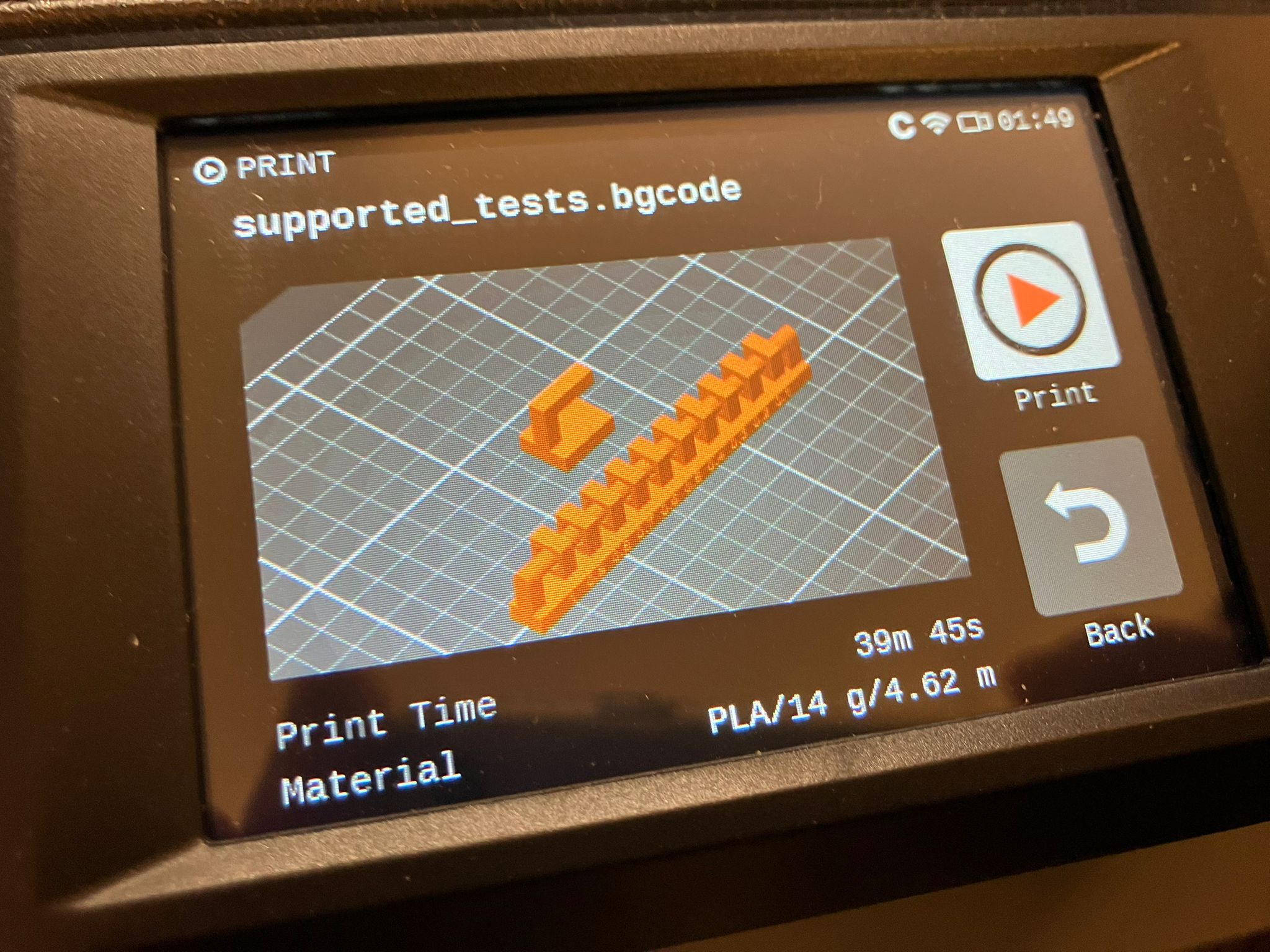
Supported tests print - grouped for efficient testing
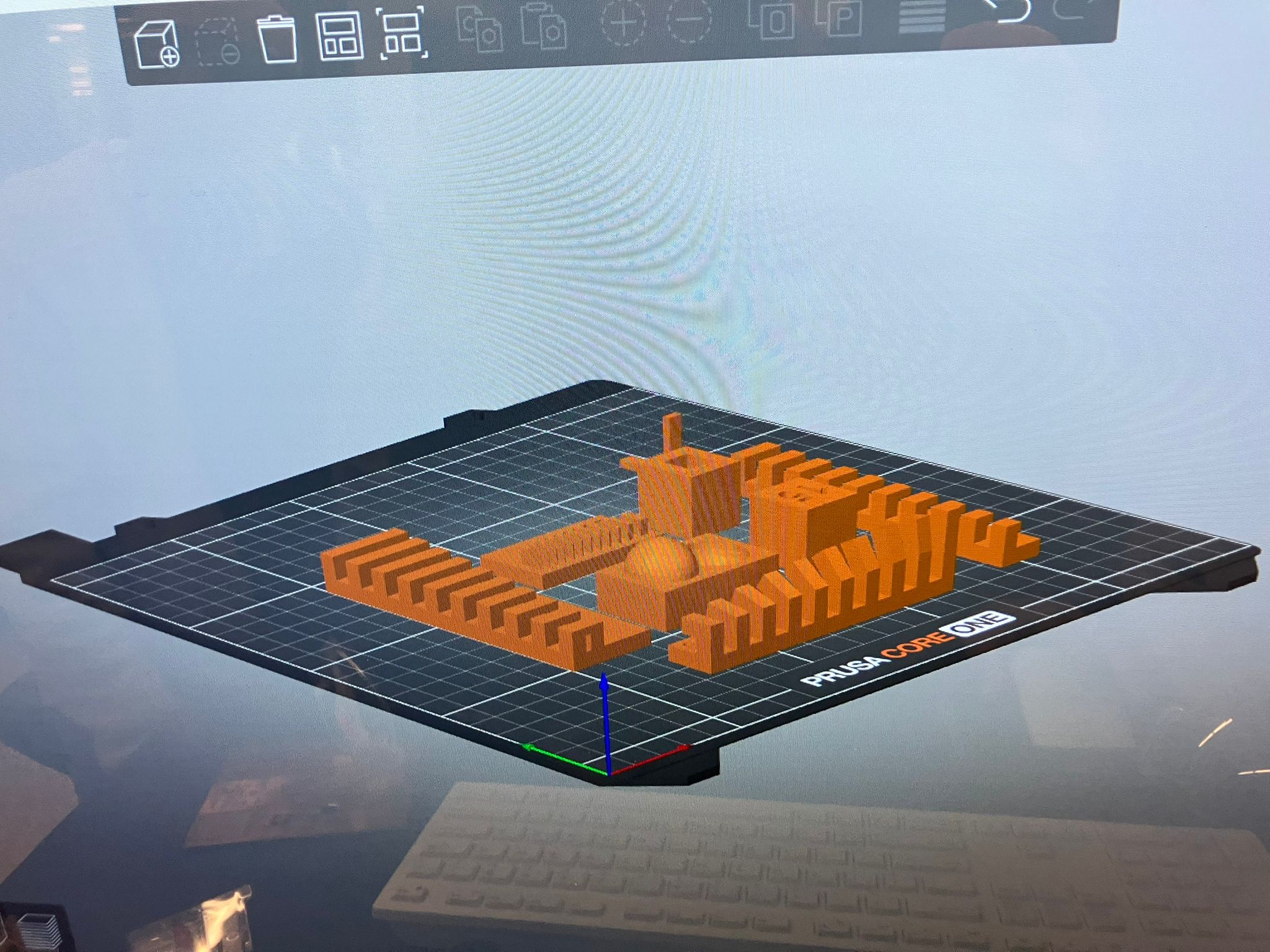
Unsupported tests print - challenging geometry evaluation
Print Strategy: By grouping all supported tests in one print and all unsupported tests in another, we were able to efficiently evaluate printer capabilities while minimizing material waste and print time. This approach allowed for direct comparison between different test geometries and provided comprehensive data on the printer's performance across various design constraints.
The supported tests focused on features that should print reliably, while the unsupported tests pushed the boundaries of what the printer could achieve without additional support structures.
References
- Lecture Notes
Course materials and technical documentation - Office Hours Insights
Instructor guidance and troubleshooting discussions - Week 3 Course Website: https://academy.cba.mit.edu/classes/scanning_printing/index.html
Official course resources and additional materials
Individual Assignment: Additive-Only Design
Design, document, and 3D print an object that could not be made subtractively. The object should be small (few cm³) and limited by printer time.
Design Requirements
- Complex geometry
Must have features impossible with subtractive manufacturing - Size constraint
Small object, few cm³ volume - Print time
Consider reasonable print time for testing - Documentation
Document design process, print settings, and results
3D Scanning Component
- Scan object
Use available scanning method to capture 3D geometry - Process mesh
Clean and prepare scanned mesh for printing - Optional printing
Print the scanned object if desired
Handgripper for Locomotive Age Assessment
I hope to design and fabricate a handgripper to measure age based on hand grip strength. This builds on our aging biomarker research by focusing on locomotive age assessment.
The idea is to measure functional decline due to aging across multiple modalities:
- Cognition: Memory, attention, reasoning, and problem-solving
- Locomotion: Mobility, balance, and muscle strength
- Sensory: Vision, hearing, and touch
- Vitality: Energy levels, nutrition, and sleep
- Psychological: Emotional well-being, resilience, and social connections
Last week we measured cognition with reaction time - this week we focus on locomotive age through grip strength.
Proposed 3D Printable Components
Untanglable Slinky
Complex interlocking geometry that cannot be manufactured subtractively. Tests printer's ability to create intricate, self-supporting structures with minimal overhangs.
Single Torsion Spring
Helical spring mechanism for grip force measurement. Demonstrates additive manufacturing's capability to create functional mechanical components in one piece.
Double Torsion Spring
Nested spring system with different spring constants. Tests printer's ability to create complex, multi-component mechanisms with varying material properties.
Coil Mechanism
Spiral coil for force transmission and measurement. Explores the limits of printable coil geometries and their mechanical properties for sensor integration.
Untanglable Slinky
A complex 3D printable design that demonstrates additive manufacturing capabilities through intricate geometry that cannot be manufactured subtractively.
Human-AI Co-Design
This design was co-developed through iterative discussion with ChatGPT, exploring various approaches to create an untanglable slinky geometry.
Design Iterations
The design process involved multiple iterations, with the first two attempts resulting in tangled slinkies that failed to maintain proper coil separation:
First attempt: Tangled slinky with improper coil geometry
Second attempt: Still resulted in tangled geometry
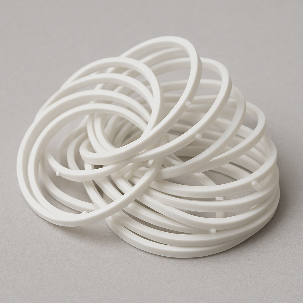
Final Successful Design
The third iteration successfully achieved the desired untanglable geometry:
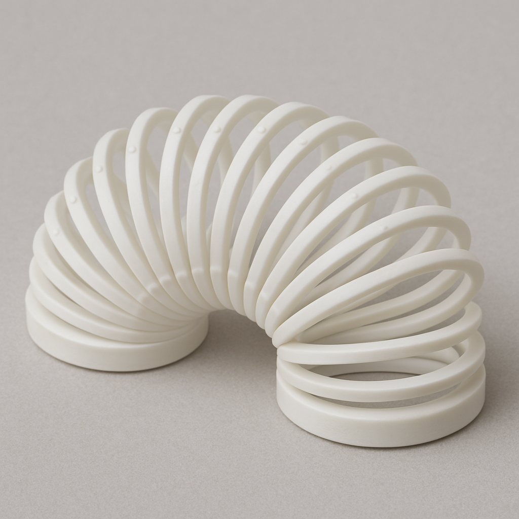
Final design: Untanglable slinky with proper coil geometry
Design Description: This design shows an untanglable slinky with flat, oval coils, tiny spacers between turns, and solid end caps, so it collapses neatly without knots. The geometry enforces orderly stacking while preventing coils from slipping past each other.
This design was co-created through iterative discussion with ChatGPT, demonstrating effective human-AI collaboration in 3D design. View the full conversation transcript in the Ethical AI Use section →
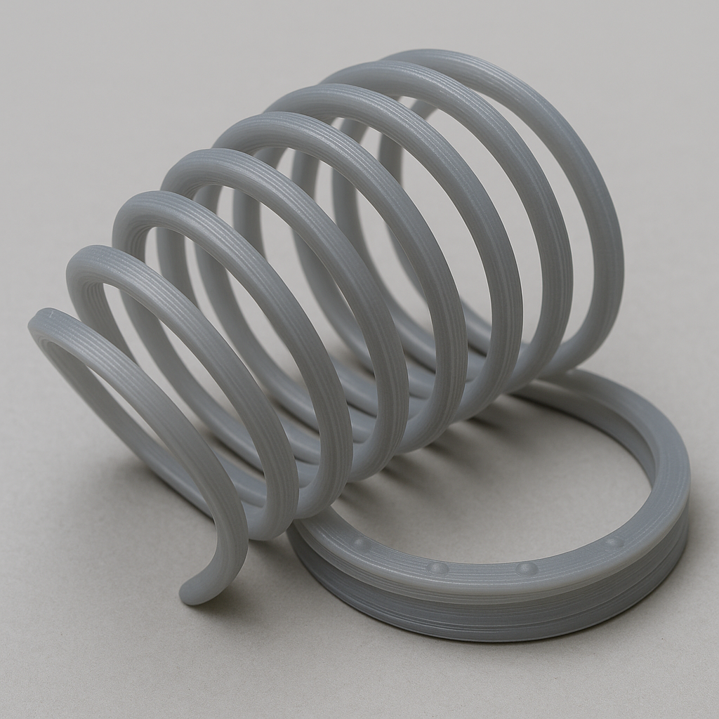
First Slinky Design
My initial exploration into creating a 3D printable slinky design, inspired by the classic magic spring concept.
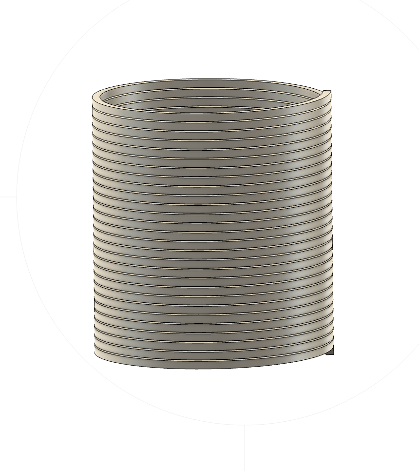
First slinky design - exploring the magic spring concept
Design Description: This first slinky design represents my initial exploration into creating a 3D printable magic spring. The design focuses on creating a helical structure that can collapse and expand while maintaining its structural integrity.
This design was inspired by the classic slinky toy and the concept of creating a "magic spring" that can be 3D printed in one piece, demonstrating the unique capabilities of additive manufacturing.
Inspiration & Resources
This design draws inspiration from several sources and builds upon existing work in 3D printable magic springs:
Video Demonstration
Watch the slinky in action: YouTube Video - Magic Spring Demonstration
3D Printable Magic Spring
Download the original design: Printables - Slinky Magic Spring
Hackaday Project
Explore the technical details: Hackaday - 3D Printed Magic Spring
The Hackaday project provides comprehensive documentation including Java code for generating G-code, print parameters, and detailed instructions for creating 3D printable magic springs. The project includes multiple iterations of the code with different features like temperature control, spiral priming, and delta printer compatibility.
Design Files
Design files are available for download in the Design Files section.
First Slinky Print
Bringing the first slinky design to life through 3D printing, testing the design's printability and mechanical properties in real-world conditions.
Print Process Documentation
The printing process involved careful preparation, parameter optimization, and real-time monitoring to ensure successful fabrication of the complex slinky geometry.
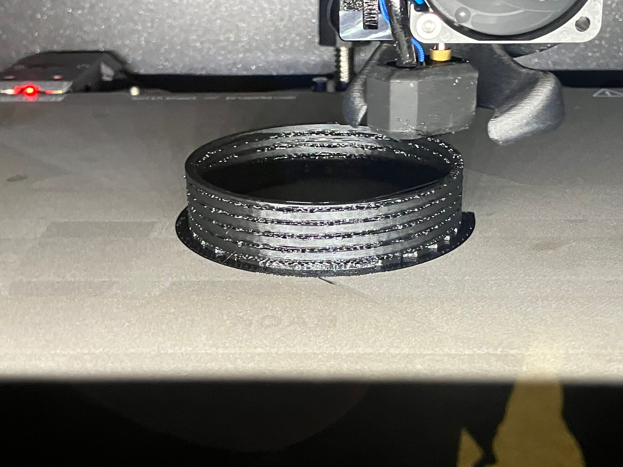
First slinky print in progress - demonstrating 3D printing of complex helical geometry
Print Process Description: The printing process successfully demonstrated the capability of FDM 3D printing to create complex helical geometries. The slinky was printed using PETG material with optimized settings for layer adhesion and dimensional accuracy. The print required careful support structure management and precise temperature control to achieve the desired mechanical properties.
Key printing parameters included: 0.4mm nozzle diameter, 0.2mm layer height, PETG material, and optimized print speed for complex geometry. The print time was approximately 55 minutes for the complete slinky structure.
Printing Video Demonstration
Watch the complete printing process in action, showing the layer-by-layer construction of the slinky's complex helical structure.
Complete printing process video showing layer-by-layer construction of the slinky
Video Analysis: This video demonstrates the successful 3D printing of the complex slinky geometry, showing how the printer handles overhangs, bridging, and intricate details. The printing process reveals the importance of proper support structures and temperature management for achieving functional mechanical properties.
Notable aspects: smooth layer transitions, successful overhang printing, proper bridging between coil segments, and consistent material flow throughout the complex geometry.
Optimization Goal & Hypothesis
The primary goal of this project is to optimize the number of revolutions that are printable in a single slinky design, pushing the limits of 3D printing capabilities for complex helical geometries.
Key Hypothesis: Since this is a slinky design, the flexible nature of the printed object should allow for pulling and stretching to remove support material from between the coils. This hypothesis drives the design optimization process, testing how many revolutions can be successfully printed while maintaining the ability to remove internal supports through mechanical manipulation.
This approach challenges traditional 3D printing constraints by leveraging the inherent flexibility of the slinky geometry to overcome support removal limitations, potentially enabling more complex and longer helical structures than would otherwise be printable.
First Success and Failure
Documenting the initial printing results and the challenges encountered with support removal, leading to refined techniques for successful slinky fabrication.
Removing Support
The first attempts at support removal revealed that simple breaking methods were insufficient for the complex internal geometry of the slinky design.
Breaking Support - Failed Method
Breaking support fails - insufficient for complex internal geometry
Razor Method - Successful Approach
Razor method works but requires caution and carefulness
Support Removal Analysis: Initial attempts at simply breaking support material proved ineffective due to the complex internal geometry of the slinky coils. The support material was too tightly integrated with the helical structure to be removed through mechanical breaking alone.
The razor method, while effective, requires extreme caution and carefulness to avoid damaging the delicate slinky structure. This process demands patience and precision to successfully remove internal supports without compromising the print quality.
Successful Results
After refining the support removal technique, the slinky prints achieved successful results with proper mechanical functionality.
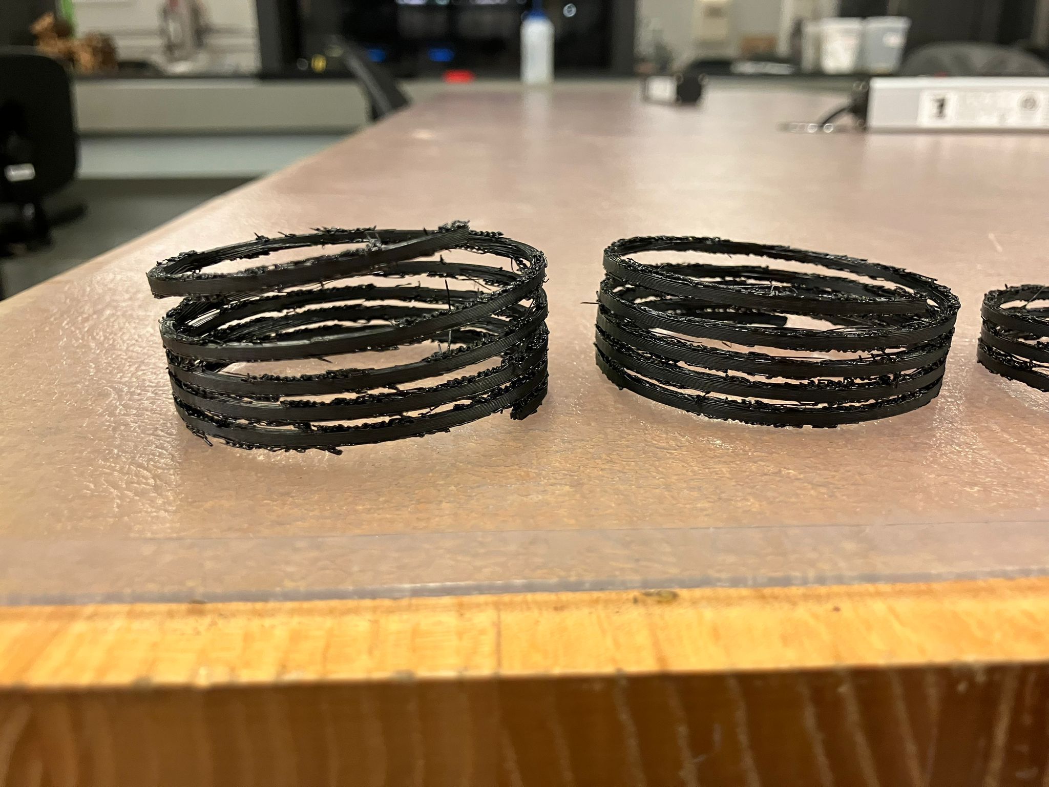
First successful slinky print - demonstrating proper mechanical functionality
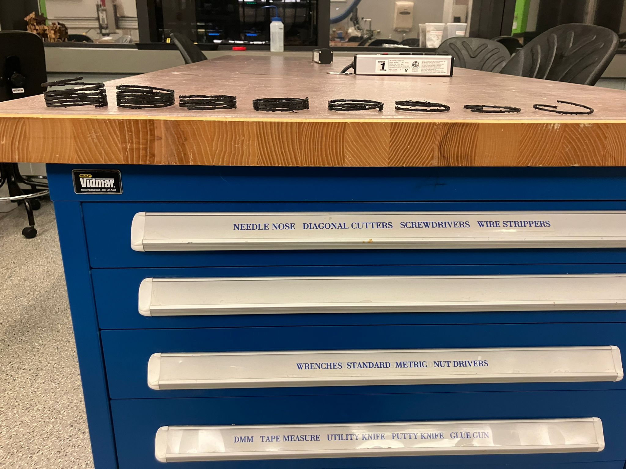
Multiple successful slinky prints - validation of design and process
Success Analysis: The successful slinky prints demonstrate the viability of 3D printing complex helical geometries with proper support removal techniques. The prints maintain their structural integrity and exhibit the expected slinky behavior, validating both the design approach and the fabrication process.
Key achievements: successful support removal, maintained geometric accuracy, functional mechanical properties, and reproducible results across multiple prints.
First Full Slinky
The final iteration of the slinky design achieved full functionality with proper mechanical behavior and successful support removal.
Fine Snipping
The final step in support removal required precise snipping to achieve clean separation and proper slinky functionality.
Fine snipping process - precise support removal for clean slinky functionality
Snipping Process: The final support removal required careful snipping with precision tools to achieve clean separation between the slinky coils and support material. This delicate process was essential for maintaining the structural integrity while enabling proper slinky movement.
Key considerations: maintaining coil geometry, avoiding damage to the helical structure, and ensuring smooth movement between coils.
Staircase Test
The completed slinky successfully passed the classic staircase test, demonstrating proper mechanical functionality and slinky behavior.
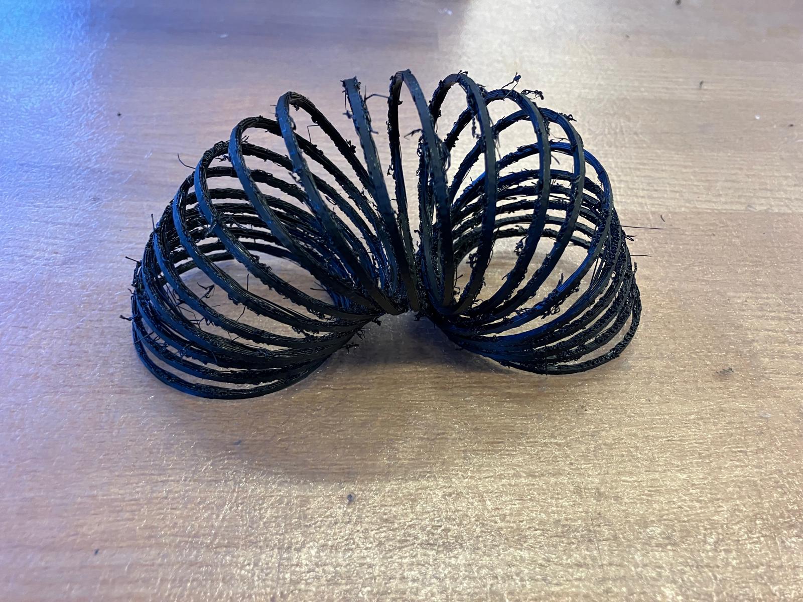
Complete full slinky - ready for staircase test
Slinky staircase test - demonstrating proper mechanical functionality
Test Success: The slinky successfully passed the staircase test, demonstrating proper mechanical functionality with smooth coil movement and the characteristic slinky behavior. This validates both the design approach and the 3D printing process for creating functional mechanical objects.
Key achievements: proper coil separation, smooth movement, maintained structural integrity, and classic slinky behavior.
Design Files
Design files and G-code are available for download in the Design Files section.
Print Success Analysis: The first slinky print successfully demonstrated the viability of 3D printing complex helical geometries. The printed slinky maintained its structural integrity and demonstrated the expected mechanical properties, proving that additive manufacturing can create functional objects with intricate geometries that would be impossible to manufacture using traditional subtractive methods.
Key achievements: successful overhang printing, proper layer adhesion, maintained geometric accuracy, and functional mechanical properties suitable for the intended slinky behavior.
3D Scanning Component
Using 3D scanning technology to capture and digitize physical objects, demonstrating the capabilities of structured light scanning systems.
Object Selection: Darth Vader Sculpture
For the 3D scanning component, I selected a detailed Darth Vader sculpture as the target object. This choice was strategic - the sculpture's complex geometry, dark surface, and intricate details would test the scanning system's capabilities and limitations.
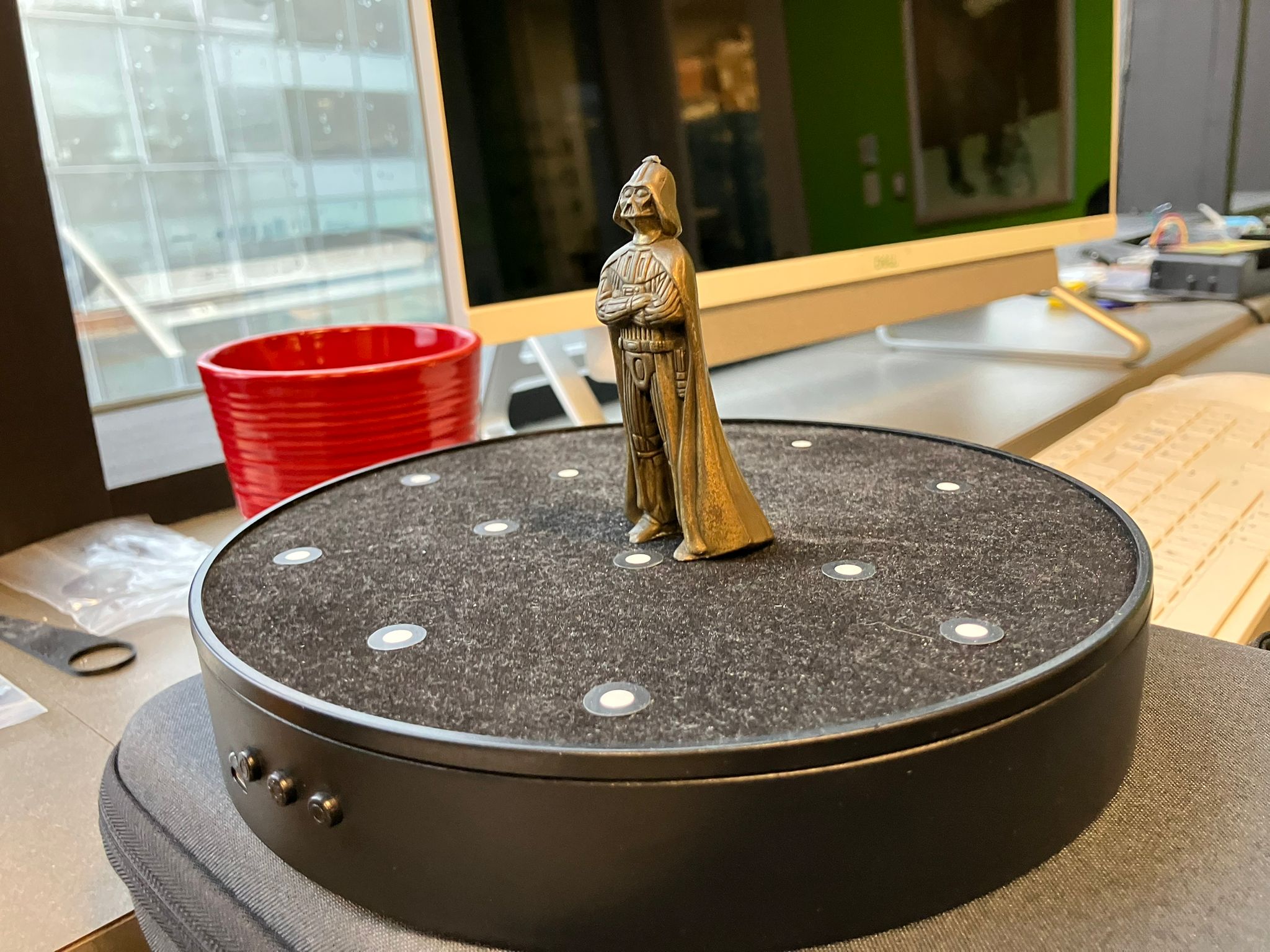
Darth Vader sculpture - complex geometry with dark surfaces and intricate details
Object Description: This detailed Darth Vader sculpture features complex geometry including flowing cape details, helmet ridges, and facial features. The dark surface material and intricate details present an excellent challenge for 3D scanning technology, testing both the system's ability to capture fine details and handle challenging surface properties.
The sculpture's combination of organic curves, sharp edges, and dark surface finish makes it an ideal test subject for evaluating scanning system performance across different surface types and geometric complexities.
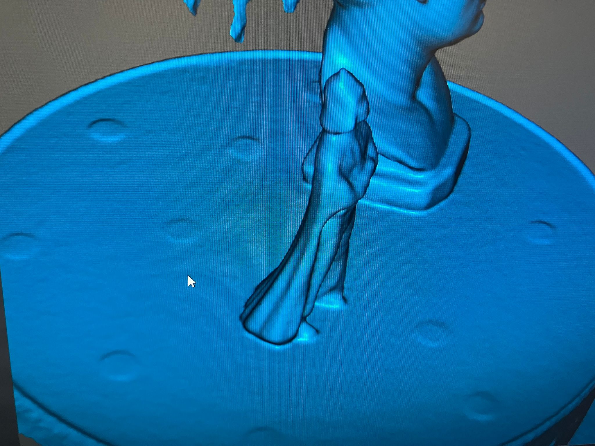
Initial Scanning Attempt: Default Settings
The first scanning attempt used default scanner settings, which proved insufficient for capturing the complex geometry and dark surfaces of the Vader sculpture.
Failed scan result using default scanner settings - insufficient detail capture
Scan Failure Analysis: The default settings failed to capture sufficient detail from the dark Vader sculpture. The resulting mesh shows significant gaps, missing geometry, and poor surface reconstruction. This demonstrates the importance of optimizing scanner settings for specific object characteristics.
Key issues identified: insufficient lighting for dark surfaces, inadequate resolution settings, and suboptimal scanning angle coverage for complex geometry.
Optimization Process
The optimization process involved adjusting scanner settings and scanning parameters to achieve better results with the challenging Vader sculpture.
Video demonstration of scanner optimization process and parameter adjustment
Optimization Process: This video demonstrates the iterative process of adjusting scanner settings, lighting conditions, and scanning parameters to achieve optimal results. The process involved multiple attempts with different configurations to find the best balance between detail capture and scanning efficiency.
Key optimization steps included: adjusting lighting intensity, modifying scanning resolution, optimizing turntable speed, and fine-tuning surface detection parameters for dark materials.
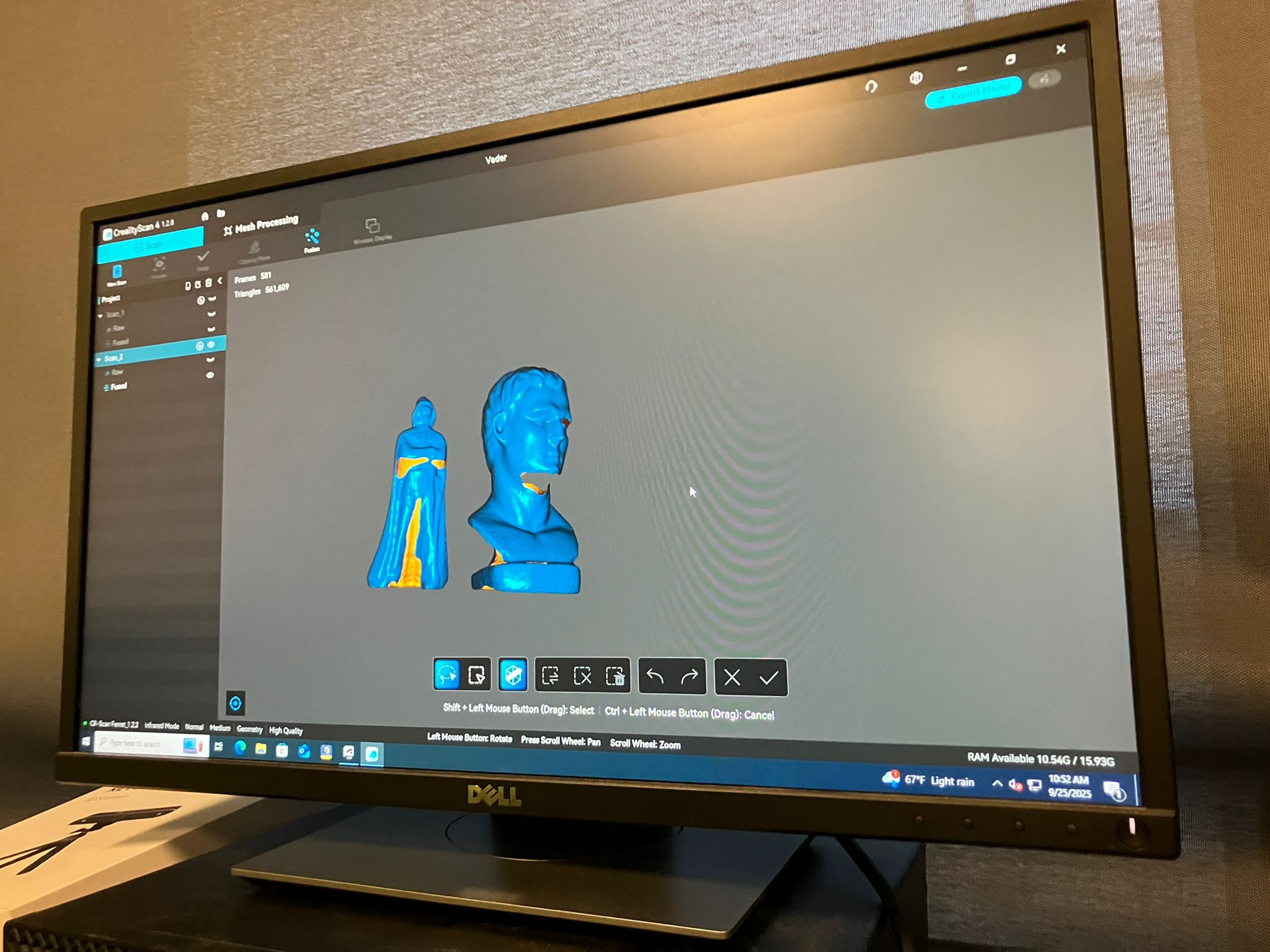
Successful Scan Result
After optimization, the scanning process successfully captured the complex geometry of the Vader sculpture with significantly improved detail and surface reconstruction.
Successful 3D scan result with optimized settings - improved detail capture and surface reconstruction
Successful Scan Analysis: The optimized scan successfully captured the complex geometry of the Vader sculpture, including fine details like helmet ridges, cape folds, and facial features. The resulting mesh shows good surface reconstruction with minimal gaps and accurate geometric representation.
Key improvements achieved: enhanced detail capture, better surface reconstruction, reduced scanning artifacts, and improved geometric accuracy for complex organic shapes.
Scan Printing
Converting the scanned Vader model into a printable 3D object required extensive post-processing and optimization for 3D printing constraints.
Post-Processing Workflow
- Initial Processing: Start with fused STL from scanner software
- MeshLab Alignment: Use MeshLab to align model to axes for proper orientation
- Meshmixer Cleanup: Import to Meshmixer, select Vader, and remove background elements
- Edge Smoothing: Smooth edges using Meshmixer tools (advice from ChatGPT consultation)
- Platform Removal: Remove floating platform to create full surface Vader
- Solid Conversion: Make model solid for 3D printing compatibility
- Final Alignment: Return to MeshLab for final alignment adjustments
- Export & Slice: Export as 3MF, slice with support everywhere (failed without support)
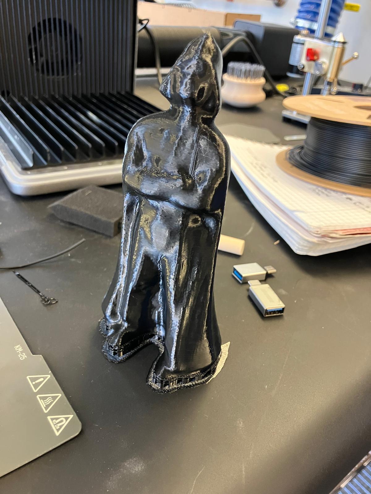
Successfully printed Vader sculpture - demonstrating 3D scan to print workflow
Print Success: The printed Vader sculpture successfully demonstrates the complete workflow from 3D scanning to 3D printing. Despite the complex post-processing requirements, the final print maintains good detail and structural integrity, proving the viability of scanning-to-printing workflows for complex organic shapes.
Key achievements: successful mesh cleanup, proper alignment, effective support generation, and successful printing of complex scanned geometry.
Helpful Documentation
Essential resources for 3D scanning, printing, and design optimization.
Lecture Information
-
3D Scanning & Printing - MIT Academy
Comprehensive resource covering 3D scanning techniques, 3D printing technologies, design for additive manufacturing, and post-processing methods. Includes tutorials on photogrammetry, structured light scanning, and various 3D printing processes.
Recitation Information
-
3D Scanning & Printing Recitation - Google Slides
Hands-on tutorial covering 3D scanning workflows, 3D printing setup and optimization, design rules for additive manufacturing, and troubleshooting common issues.
Design Files
Links to CAD files, STL files, and other design assets for this week's assignments.
Group Assignment - 3D Printing Design Rules Test Files
Comprehensive STL files for testing various 3D printing design rules and constraints:
Slinky Design Optimization
Complete set of slinky design files and G-code for testing printable revolution limits and support removal hypothesis:
3MF Design Files
first_slinky_28 v1.3mf
Initial slinky design with 28 coil iterations - testing maximum printable length
📥 Downloadfirst_slinky_28_2 v1.3mf
Refined version of the 28-coil slinky design with optimized geometry
📥 Downloadthird_slinky_21 v1.3mf
Third iteration with 21 coils - balanced design for printability and functionality
📥 Downloadfourth_slinky_7 v1.3mf
Fourth iteration with 7 coils - compact version for testing support removal hypothesis
📥 DownloadG-code Files
first_slinky_28_2 v1.bgcode
G-code for 28-coil slinky (51 minutes print time) - maximum length test
📥 Downloadsecond_slinky_14 v1.bgcode
G-code for 14-coil slinky (58 minutes print time) - mid-range optimization
📥 Downloadthird_slinky_21 v1.bgcode
G-code for 21-coil slinky (55 minutes print time) - optimal balance
📥 Downloadfourth_slinky_7 v1.bgcode
G-code for 7-coil slinky (57 minutes print time) - support removal test
📥 DownloadDesign Iteration Strategy: These files represent a systematic approach to optimizing printable slinky designs. Each iteration tests different coil counts to find the maximum number of revolutions that can be successfully printed while maintaining the ability to remove internal supports through mechanical manipulation of the flexible slinky structure.
The progression from 7 to 28 coils allows for testing the limits of 3D printing capabilities while validating the hypothesis that slinky flexibility enables support removal in complex internal geometries.
First Slinky Design
Design files for the first slinky exploration project:
Reflections & Learnings
Key insights and lessons learned from working with 3D printing and scanning technologies.
Key Points
- Complex geometries require understanding additive manufacturing constraints—geometry complexity directly affects printability
- Support material strategies must be tailored to each design's specific geometry and orientation requirements
- Iterative refinement is essential for complex parts—multiple print iterations needed to achieve desired functionality
- Material selection and print settings profoundly impact part quality and mechanical properties
- 3D scanning requires careful environment preparation and multiple scan angles for complete geometry capture
3D Printing Process Insights
- Understanding design constraints and limitations of additive manufacturing is crucial—the untanglable slinky project revealed how geometry complexity affects printability and functionality.
- Support material strategies vary significantly by design—some geometries require careful orientation and support placement, while others can be printed with minimal or no supports.
- Iterative design refinement is essential when working with complex geometries; multiple print iterations were necessary to achieve the desired slinky functionality.
- Material selection and print settings have profound impacts on final part quality and mechanical properties, requiring systematic testing and characterization.
3D Scanning Learnings
- Successful 3D scanning requires careful preparation of both the object and scanning environment—lighting, object surface properties, and scanning technique all significantly impact results.
- The workflow from scan to printable model involves multiple processing steps including mesh cleanup, hole filling, and geometry repair.
- Scanning complex objects like the Darth Vader sculpture demonstrated the importance of multiple scan angles and proper alignment for complete geometry capture.
Contributions
Acknowledgements and team roles for this week's work.
Contributions will be documented as work progresses
Ethical AI Use
Documentation of AI tool usage for this week's assignments and design work.
📋 General Guidelines: See General Commands for Cursor on the homepage for standard guidelines and commands used consistently throughout documentation development.
Week 3 - 3D Scanning and Printing Development
This session covers the development of the Week 3 page for 3D scanning and printing, including content population from MIT Academy resources, navigation updates, and design file integration.
Key Activities
- Week 3 page creation from template
- Content population from MIT Academy
- Navigation button integration
- Design file organization
AI Tools Used
- Cursor AI for code generation
- Content structuring and formatting
- File organization and linking
- Design consistency maintenance
Untanglable Slinky Co-Design Session
This session documents the iterative co-design process for creating an untanglable slinky using ChatGPT. The conversation shows multiple design iterations, from initial failed attempts to the final successful geometry.
Design Process
- Initial geometry exploration
- Iterative refinement process
- Problem-solving for tangling issues
- Final successful design
AI Collaboration
- ChatGPT for geometry suggestions
- Iterative feedback and refinement
- Problem diagnosis and solutions
- Design validation and testing
Responsive Design Repository Refactoring
This session documents the comprehensive refactoring of the entire web development repository to make it fully responsive and mobile-friendly. The conversation covers the implementation of modern CSS techniques, responsive design patterns, and mobile-first development approaches.
Key Activities
- Responsive CSS framework creation
- Mobile-first design implementation
- Video container optimization
- Typography and spacing refactoring
AI Collaboration
- Cursor AI for responsive design
- CSS framework architecture
- Mobile optimization strategies
- Cross-browser compatibility
First Slinky Design Integration
This session documents the integration of the first slinky design into the untanglable slinky section, including adding the image, description, inspiration resources, and design file links.
Key Activities
- First slinky design integration
- Image and caption addition
- Resource links implementation
- Design files section restructuring
AI Collaboration
- Cursor AI for content integration
- HTML structure optimization
- Design file organization
- User experience enhancement
Vader Scan Post-Processing Consultation
This session documents the consultation with ChatGPT for optimizing the Vader scan post-processing workflow. The conversation focused on edge smoothing techniques in Meshmixer and best practices for preparing scanned meshes for 3D printing.
Technical Focus
- Meshmixer edge smoothing techniques
- Mesh cleanup optimization
- 3D printing preparation
- Surface quality improvement
AI Collaboration
- ChatGPT for technical guidance
- Software-specific recommendations
- Workflow optimization advice
- Problem-solving assistance
Week 3 Individual Assignment Development & Updates
This session documents the development and updates to the Week 3 individual assignment focusing on 3D scanning and printing. The conversation covers 3D scanning techniques, Vader model processing, slinky design iterations, and individual project implementation.
Individual Project Focus
- 3D scanning workflow development
- Vader model post-processing
- Slinky design iterations
- Individual assignment documentation
AI Collaboration
- Cursor for individual project structuring
- 3D scanning guidance and troubleshooting
- Design iteration support
- Technical implementation assistance
Week 3 Group Assignment Development & Updates
This session documents the comprehensive development and updates to the Week 3 group assignment focusing on 3D printing design rule testing. The conversation covers group collaboration, design rule testing methodology, PDF content extraction, and group project implementation.
Group Project Focus
- 3D printing design rule testing
- Group assignment documentation
- PDF content extraction and integration
- Collaborative design methodology
AI Collaboration
- Cursor for group project structuring
- PDF content extraction assistance
- Design rule testing guidance
- Group collaboration workflow optimization
 This work is licensed under a
Creative Commons Attribution-NonCommercial-ShareAlike 4.0 International License
This work is licensed under a
Creative Commons Attribution-NonCommercial-ShareAlike 4.0 International License