Fabrication
& Assembly
From raw FR1 copper stock and PLA filamentto a finished product. The fabrication process involved precision CNC milling, surface mount soldering, testing connectivity and signals of stuffed boards and 3D printed enclosure design.
01 · PCB Fabrication
The PCB was milled on a Bantam Tools Desktop CNC Milling Machine using FR1 single-sided copper stock.
- Traces: 1/64" flat end mill.
- Holes & Outline: 1/32" flat end mill.
- Clearance: 0.2mm minimum trace clearance.
The Process
- CAM Setup: Imported Gerber files into Bantam Tools software. Configured tool paths for traces, holes, and outline.
- Fixturing: Secured FR1 stock to the spoilboard using double-sided Nitto tape.
- Milling: Started with 1/64" end mill for very fine and detailed traces, then switched to 1/32" for larger traces, drilling holes, and cutting the board outline. Total run time was approximately 15 minutes per board.
- Post-Processing: Deburred edges with a Scotch-Brite pad and washed with soap and water to remove dust.
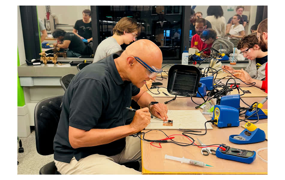
02 · Assembly & Soldering
All components were hand-soldered. The design uses a mix of through-hole (headers, terminals) and surface mount (resistors, capacitors) components. The assembly process required careful attention to component placement and creative solutions for mounting breakout boards.
Component-by-Component Assembly Process
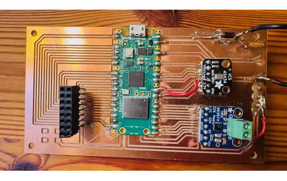
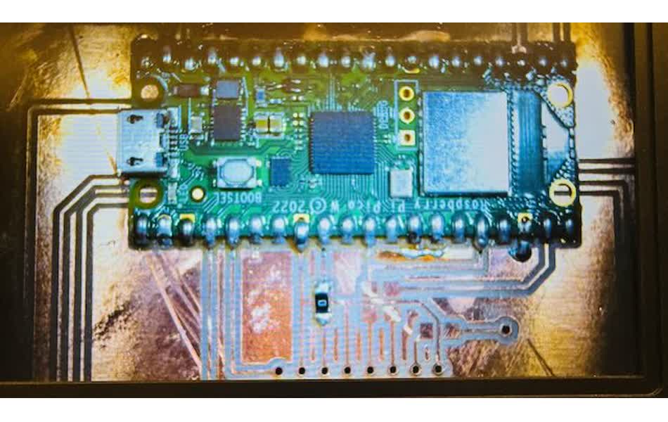
1. Raspberry Pi Pico W
Soldered the Pico W directly to the PCB using a temperature-controlled soldering iron and leaded solder. The digital microscope display was invaluable for reviewing solder joints in real-time, ensuring clean connections without bridges between pins.
2. HUB75 Connector
For the HUB75 connector to the LED matrix, I used two rows of 8-pin header pins—one row on top and one on bottom. This dual-row approach provided excellent mechanical stability for the high-density connector that carries 16 data and control signals.
3. MAX98357 I²S Audio Amplifier
The I²S amplifier breakout board was mounted on header pin "stilts" above the PCB surface. This elevated mounting approach was necessary because the board's layout footprint in Fusion 360 accounted for the breakout board's physical dimensions. The stilt mounting also improves airflow around the Class-D amplifier.
4. ICS-43434 I²S MEMS Microphone
The I²S microphone breakout board used the same header pin stilt technique as the amplifier. This keeps the microphone elevated and oriented properly for optimal audio pickup while maintaining electrical connectivity to the PCB traces below.
5. Power Connector
The power connector was fashioned from thick header pins with a plastic side sleeve. Due to the single-sided PCB design with traces on top, the connector had to be inserted from below the PCB front.
This awkward bottom-mounting will be corrected in the boards I've ordered from JLCPCB.com. With professionally manufactured boards, the vias come anodized (plated through-holes), allowing power connectors to be mounted on top of the PCB with headers soldered cleanly at the bottom—the proper way.
6. 5V Power Jack
The 5V power housing was a standard component that Anthony Pennes ordered for me. This replaced the earlier prototype's unstable hanging power lines with a proper barrel jack connector, making power connection much more reliable and professional.

03 · Enclosure Design
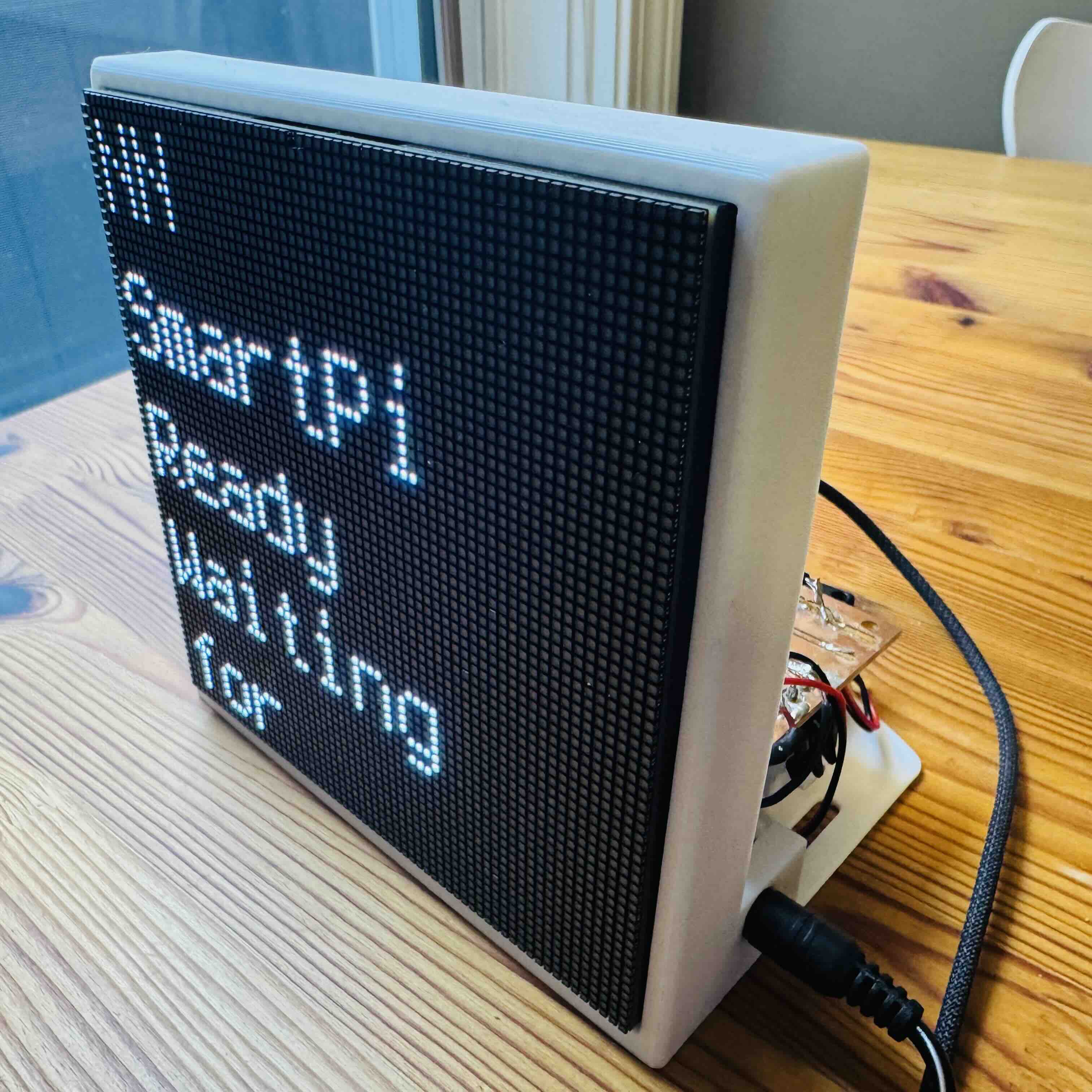
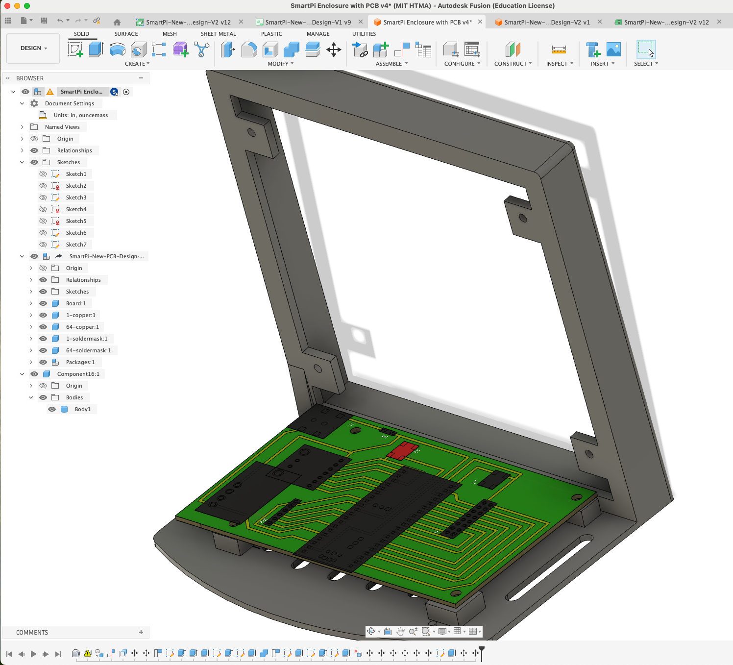
The enclosure was designed in Fusion 360 to house the 64x64 Matrix, the PCB, and the speaker. A critical aspect of the design was precisely positioning mounting points for both the PCB and the LED display.
Fusion 360 Design Process
The enclosure design started by importing the PCB outline from the Eagle/Fusion board file. This allowed me to:
- Import PCB Outline: Imported the .brd file directly into Fusion 360, which automatically extracted the board dimensions and mounting hole positions.
- Create Mounting Pads: Projected the mounting hole locations onto the enclosure base and created raised pads with integrated screw bosses for M3 screws. These pads provide structural support and ensure the PCB sits level.
- LED Display Integration: Repeated the same process for the Waveshare 64×64 LED matrix panel, creating four mounting bosses that align with the panel's mounting holes.
- Clearance Verification: Used section views to verify component clearances, especially around tall components like the HUB75 connector and power terminals.
Prusa Slicer and G-Code Generation
After completing the 3D model in Fusion 360, I exported it as an STL file and imported it into PrusaSlicer to prepare it for printing. PrusaSlicer is Prusa Research's open-source slicing software that converts 3D models into G-code instructions that the printer can execute.
The slicing process involved configuring several key parameters:
- Printer Selection: Prusa i3 MK3S+ profile with appropriate bed size and print volume
- Material: Generic PLA filament settings optimized for layer adhesion and surface finish
- Layer Height: 0.2mm for a balance between print quality and speed
- Infill: 20% grid pattern providing sufficient structural strength while minimizing material usage
- Supports: Organic tree-like supports enabled for overhanging features, with support on build plate only
- Support Overhang Angle: 50° threshold to minimize support material while ensuring print success
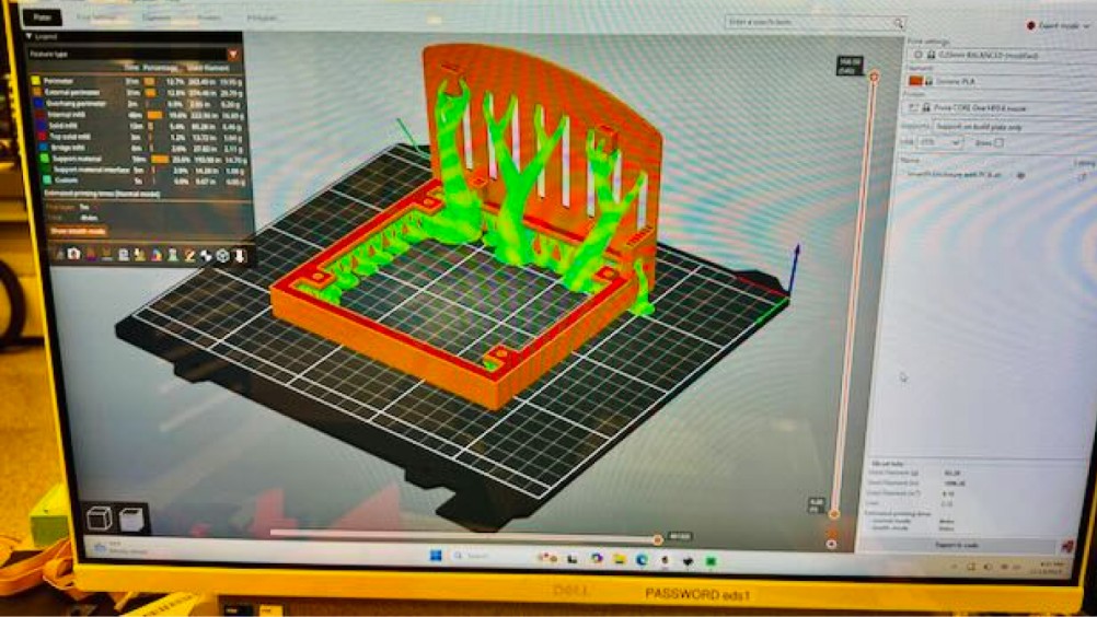
Once all settings were configured, PrusaSlicer generated the G-code file containing layer-by-layer instructions. The software provided an estimated printing time and material usage, allowing me to verify the print would complete successfully before sending it to the printer.
3D Printing with PLA Filament
The enclosure was printed on a Prusa i3 MK3S+ 3D printer using PLA (Polylactic Acid) filament. PLA is an ideal choice for this application due to its ease of printing, good dimensional accuracy, and sufficient strength for a static enclosure housing electronic components.
PLA offers several advantages for this project:
- Low Warping: PLA has minimal shrinkage and warping during cooling, ensuring accurate dimensional tolerances for mounting holes and screw bosses
- Good Layer Adhesion: The 0.2mm layer height provides strong inter-layer bonding for structural integrity
- Surface Finish: PLA produces smooth, matte surfaces that look professional without post-processing
- Temperature Stability: For indoor use, PLA's glass transition temperature (~60°C) is more than adequate
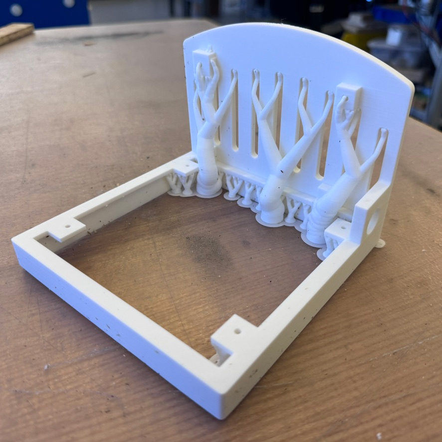
The organic support structures generated by PrusaSlicer provided necessary support for overhanging features while using minimal material. These tree-like supports are more efficient than traditional grid supports, reducing material waste and making post-processing easier. After printing, the supports were removed by hand, revealing the clean mounting pads and screw bosses ready for component assembly.
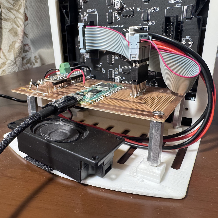
Mounting PCB and LED Display
With the enclosure printed and supports removed, the final assembly process involved mounting the stuffed PCB and the 64×64 LED matrix display onto the enclosure using M3 standoffs and screws. The precisely positioned mounting bosses created in Fusion 360 ensured perfect alignment of all components.
The assembly process followed these steps:
- PCB Mounting: The stuffed PCB was secured to the enclosure using M3 standoffs threaded into the raised mounting pads. The standoffs provide proper clearance between the PCB and the enclosure base, preventing shorts and allowing airflow around components.
- LED Display Mounting: The Waveshare 64×64 LED matrix panel was mounted using M3 screws directly into the four mounting bosses designed specifically for the display panel. The panel sits flush against the front of the enclosure, with the display visible through the opening.
- HUB75 Connection: The HUB75 ribbon cable was connected between the PCB's dual-row header connector and the LED matrix panel, carrying all 16 data and control signals for the display.
- Power Connection: The 5V power supply was connected to the PCB's power jack, providing power to both the Raspberry Pi Pico W and the LED matrix display.
- Speaker Mounting: The 3W speaker was positioned at the designed location within the enclosure's ported chamber for optimal acoustics. The speaker was secured using Velcro, allowing for easy adjustment and removal if needed while maintaining a secure fit during operation.
- Final Connections: All wiring was routed cleanly within the enclosure, ensuring no interference with moving parts or components, and the enclosure was snapped together for final assembly.
Design Goals
- Compactness: Minimize volume while fitting all components.
- Precision Mounting: Accurate screw boss placement for both PCB and LED display using imported outlines.
- Acoustics: Ported chamber for the 3W speaker to enhance bass response.
- Modularity: Snap-fit design for easy access to internals.
Manufacturing
- Printer: Prusa i3 MK3S+
- Material: PLA (Matte Black)
- Layer Height: 0.2mm
- Infill: 20% Grid
- Support: None required due to careful orientation
Importing the PCB board file directly into Fusion 360 ensures mounting holes are positioned with sub-millimeter accuracy. This eliminates the need to manually measure and transfer dimensions, which is error-prone. The technique works for any Eagle or Fusion 360 electronics design.
04 · Final Integration
The final assembly brought everything together. The PCB mounts to the back of the LED matrix using M3 standoffs. The speaker is press-fitted into the enclosure, and the entire unit snaps together.