<br>
### Aluminum Recycling
#### Joonhaeng Lee and Nathan Melenbrink
### Update 5/19/2021
Last week, we tested the stiffness of the sintered sand and figured out that sintered sand is stiff enough to maintain its form. Even though it's a bit brittle, it can still be carved or otherwise shaped without cracking. So, today, we tested whether the sintered sand can be used as a casting mold.
In conventional lost PLA casting, the printed part is cast into plaster, which is then fired at a low temperature to melt out the PLA. Then, aluminum is heated in a crucible and poured into the plaster form. This process has been shown to produce high-quality, detailed aluminum parts. We are interested to see if we can make rough casts while reducing the number of steps required.
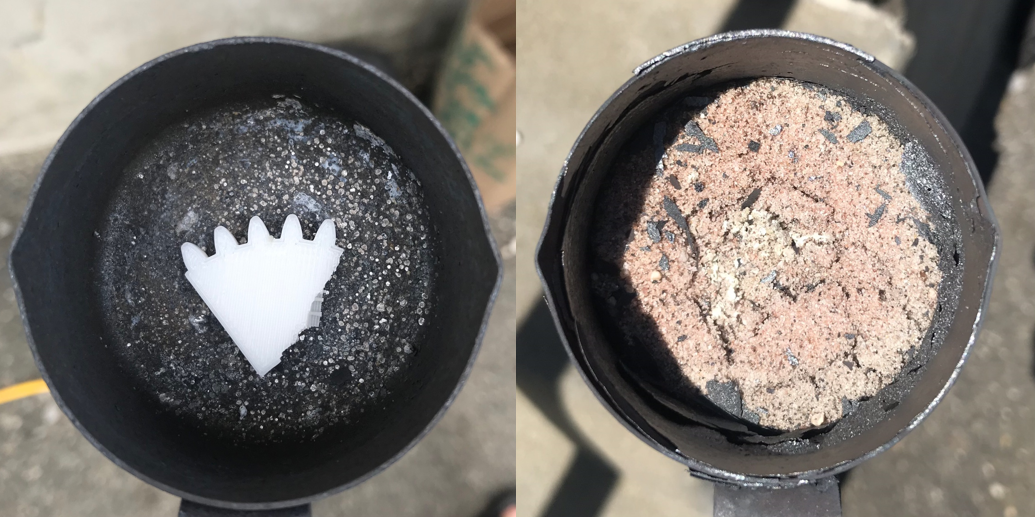
#####PLA part + Sand(~1mm)| 2000F 30min <!-- | start at 60F pull out at 400F -->
We know that PLA has a melting temperature of 320 °F, but could not find a specific burning temperature. We can expect that the PLA will burn before the sand is sintered enough to hold its shape, but figured it was worth trying to be sure. So we tried the fired 3D printed part surrounded by sand, firing for 30 min. (We forgot to take a photo of the PLA part surrounded by sand). We could see some remaining white PLA ash residue from the result, but most of it was burned and disappeared. However, the PLA part was not strong enough to make its section profile shape on surrounding sand. So we think that PLA burns out at a much lower temperature than the temperature that sand starts to sinter (~2000F).
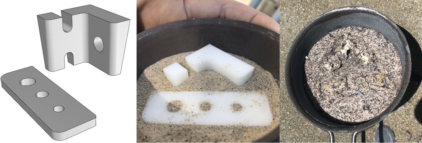
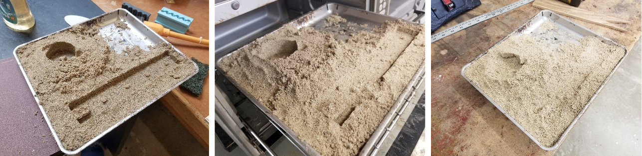
#####PLA part + Sand (sieved ~1mm) | 2000F 120min <!-- | pull out at 200F -->
We did a similar test using a 30mm height L shape PLA part and one flat 10mm height part with different-sized holes. Since the height of the L-shaped part was 30mm, we had to pour a lot of sand compared to previous tests. So, we fired those for 2 hours and wait for about 30 minutes to gradually cool it down. We can see some profile traces, but the PLA parts again burned too quickly to make a void for casting.
<video height="500" autoplay loop muted>
<source src="img/furnace/210519_Al Casting_04.mp4" type="video/mp4">
Your browser does not support the video tag.
</video>
#####Hand carving
We want to confirm whether sand in the interior of the sample sintered, and it was.
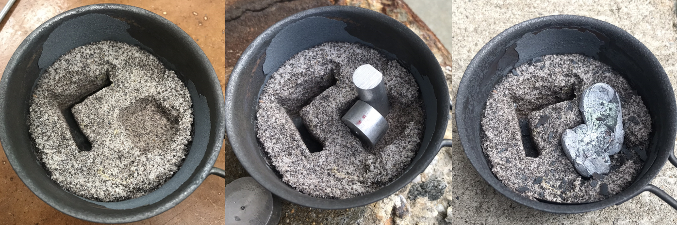
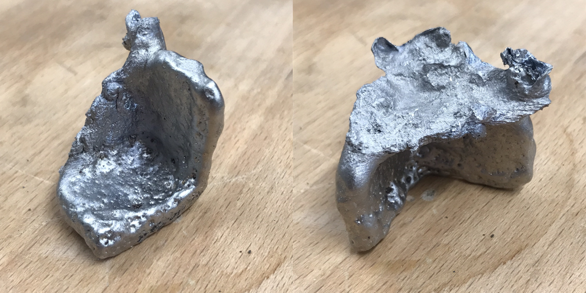
#####Carved sintered sand + Aluminum scrap | 2000F 120min <!-- | pull out at 200F -->
On top of the hand-carved mold, we tested aluminum casting in two different ways, a) putting scrap on the pattern and letting it melt in the furnace, and b) pouring molten aluminum directly. Based on previous tests, we expected surface tension would maintain the original scrap's shape. That wound up happening again. Even after poking the sample with tongs, the liquid still did not fully escape the oxidized surface and failed to fill the mold cavity.
<!-- We poked once after 30 minutes of heating (video below).
<video height="500" autoplay loop muted>
<source src="img/furnace/210519_Al Casting_05.mp4" type="video/mp4">
Your browser does not support the video tag.
</video>
##### Surface tension removal-->
##### Molten Aluminum Casting
Since our attempts at in-situ casting were less than successful, we decided to try some more conventional methods.
For the L shape, we poured aluminum directly into the void space. Also, in this test, we tested lost foam casting methods as well.
<video height="500" autoplay loop muted>
<source src="img/furnace/210519_Al Casting_01.mp4" type="video/mp4">
Your browser does not support the video tag.
</video>
<video height="500" autoplay loop muted>
<source src="img/furnace/210519_Al Casting_02.mp4" type="video/mp4">
Your browser does not support the video tag.
</video>
<video height="500" autoplay loop muted>
<source src="img/furnace/210519_Al Casting_03.mp4" type="video/mp4">
Your browser does not support the video tag.
</video>
##### Casting Results | 30 min cooling in mold, then put in water
Pull out pieces from the sintered sand mold, as well as the loose sand used for lost foam casting.
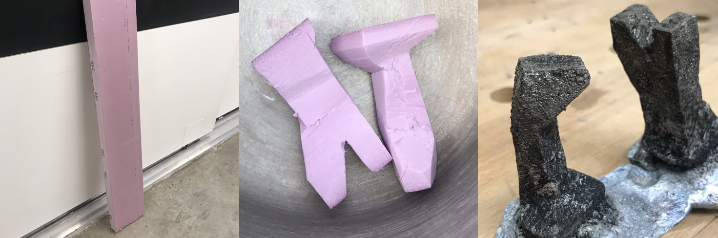
##### Lost foam mold test results
##### Sintered sand mold results
### Update 5/8/2021
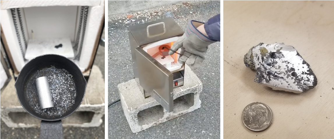
Today we first tried melting a 12g piece of scrap aluminum at a temperature of 1000 °C for 30 minutes. We expected the aluminum to melt, but found that the scrap part's surface tension (presumably fortified by oxidation) kept the liquid aluminum from escaping. When we poke the sample with tongs, the surface ruptured and the liquid aluminum spilled out. We also threw in a couple balls of aluminum foil, which melted quickly upon contact with the molten aluminum. Once cooled, we filed down the sample to get a sense of its material properties. There were plenty of impurities, but the part was strong compared to PLA, and could be drilled and tapped, and presumably machined. Next, we will look into additives that reduce the surface tension of molten aluminum.
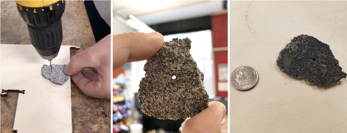
We also tried sintering Quickrete brand play sand (the most generic sand available to us), for 60 minutes at 1200 °C. Surprisingly, the material properties changed considerably. The sample was brittle, but rigid. We were able to drill a hole in one piece without cracking the sample. Presumably, with a little longer hold time we could produce a machinable sample.
### Update 5/6/2021
We tried heating the aluminum shot by itself, at a temperature of 1000 °C for 30 minutes. Based on everything we've read, this should definitely melt the aluminum.
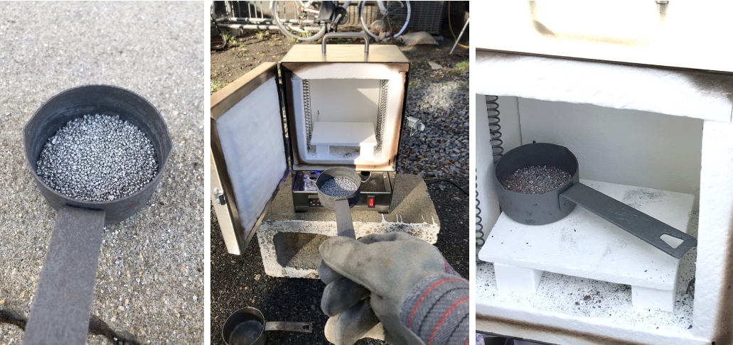
Unfortunately, it still did not melt. Even though the sample was glowing red, the surface tension of the individual pellets kept the sample from becoming liquid. The result still crumbled apart.
We then tried regolith again. We compacted it and excavated a channel. That turned out not to matter. After 60 minutes at 1100 °C, the regolith had heated well beyond the point of sintering. This was a bit of a surprise; we expected that this particular regolith simulant would have a high melting/sintering temperature because of its high plagioclase content. The result is a very foreign material that doesn't quite resemble any other ceramic we're familiar with. We don't want to speculate on the extreme porosity of the sample. It could have to do with the rapid cooling (we assume this is also what caused the spalling of the steel container). We don't expect that this will be a problem at lower temperatures.
We will get additional types of regolith simulant next week. We will then run a series of experiments to dial in the temperature and hold time to fully sinter, but not melt, the sample matrix.
### Update 5/4/2021
Our furnace arrived, and after fixing the faulty electronics (!) we ran a first firing as instructed by the manufacturer.
We then placed some regolith simulant in a steel measuring cup, compacted it and tried to carve out a pattern (not very successfully). We put some aluminum shot in another measuring cup, and put both in the furnace at 1100 °C for an hour.
After allowing the furnace temperature to slowly come down, we removed the containers to find that very little had happened. The aluminum shot was pasty and somewhat stuck together, but easily crumbled back into shot. The regolith was slightly firmer, but not nearly stiff enough to make a mold. So for next time, we adjusted the furnace platform to allow more space for better convection and decided to work with smaller amounts.
### Update 4/28/2021
We ordered a furnace, but shipping is delayed. We hope to receive it the end of this week. We have also ordered and received regolith simulant (just 1 kg to test for now). We had another helpful conversation with Zach and walked through our plan and safety precautions. As soon as we get the furnace, we'd like to test whether it is possible to make molds by sintering regolith simulant. [This paper](https://www.sciencedirect.com/science/article/pii/S0094576521000564) provides some guidelines:

* The used newly developed regolith simulants from TU Braunschweig. We don't have access to those, but we could compare the chemical compositions.
* The sintering temperature is either 1050 °C for particles sieved at 90 μm or 1100 °C for the original particle distribution.
* Slight compaction before sintering (references 32-34 for sintering bricks). Compaction was found to reduce cracking due to temperture shock.
* Prioritized mold reuse in order to be classified as a permanent mold (not important to us).
* Hold time of one hour. Expect slight shrinkage.
* They experienced cracking due to temperature shock and anyway had to heat the molds to 500C before casting.

* In powder form, they found that the regolith simulant has a contact angle with aluminum higher than 90°, which means that the aluminum was unable to flow into corners and tight features. Wetting angles were much better with the sintered regolith.
* They found less surface roughness with the sintered mold than with the powder mold.
[Another paper](https://ascelibrary.org/doi/10.1061/%28ASCE%29AS.1943-5525.0000205) from 2013 contrasts solar sintering with sintering in a lab furnace. A main finding was that the glass content of the regolith simulant was the primary factor driving whether a desirable sintering result could be achieved. They tried small (10 mg) samples at 1000-1200 °C and held the temperature for only 1 minute. They found that for each simulant, the last mineral to melt was plagioclase (unfortunately, this means we probably bought the most difficult type of regolith simulant to sinter...we can order the other types as well).
### Update 4/8/2021
Joon and I had a very helpful conversation with Zach Fredin on Friday. Some of the main points:
* Prioritize simple tests. Unfortunately we still don't have access to a furnace, but will soon. Zach pointed out how there's not much precedent for heating molds simultaneously with the casting metal, so it will be important to try this out.
* Specifically, where will the impurities end up, if there's no means of removing them during heating? We can hope that they'll all rise to the top, and can then be easily milled off. But we'll have to try it soon.
* Use resin-bonded or oil bonded sand. Green sand will likely dry out before the aluminum melts. I confirmed this with wet sand in a 450F toaster oven:
While the sand seems to hold its form after it has dried, a slight bump and it returns to its angle of repose. Certainly melting aluminum could cause enough disturbance to collapse the mold.
I'm now looking for recipes for resin or oil bonded sand that would require minimal rejuvenation in order to reuse. [This paper](https://www.sciencedirect.com/science/article/pii/S0094576521000564) suggests that it's not possible, or at least not suitable for space applications. Instead, they have success with sintering regolith simulant at ~1100, which hardens the regolith simulant. I wonder how generalizable that is? Will it work for all kinds of regolith simulant? Ordinary play sand? What's the best way to prepare a sintered mold? First stamp the pattern and then sinter the mold, or first sinter the whole flask and then mill out the cavity?

Assuming we can replicate these results, the way in which we'd differentiate our work would include:
1. Minimizing the number of steps needed (not modifying the mold after sintering).
2. Addressing the source of the scrap aluminum (the German paper uses powder and pours the mold from a conventional crucible).
3. Potentially not needing a 3D printed pattern (if the shape can be directly milled into the sintered regolith).
4. Machining rough-cast parts after casting. The German paper did not inspect the parts for impurities or perform any mechanical tests. We would want to demonstrate that direct-cast parts could be useful after finish-pass milling.
### Update 4/1/2021
After considering 3 options for machine configurations last week, it became clear that a common requirement would be some method of automating the clamping of stock material to a machine bed.
#### Automated vise
I did some searching and was surprised to find very little in the way of automated workpiece clamping. Am I searching the wrong terms? I found pneumatic or "power" clamps that are used in industrial processes, but I didn't find much else:
<img src='https://www.datron.com/wp-content/uploads/2015/10/Pneumatic_Clamp_CNC_Workholding.jpg' alt='Pneumatic Clamp' >
I'm imagining a device that consists of a vise actuated by a stepper motor (gear ratio TBD). There would be some embedded force sensing, such that the vise could be commanded to clamp to a predetermined amount of force. What's the best way of measuring force here? Load cell, piezo transducer, capacitive sensor, current sensing?
One idea would be to design the vise to work with standard T-slots. The sacrificial material (brown) may need to feature slots as well.
<img src='./img/0.jpg' alt='Pneumatic Clamp' width='1000' >
An input (assume a button press, but could also be proximity sensor) signals that there is stock in the vise. The vise closes by turning the stepper motor until the desired clamping force is achieved.
<img src='./img/1.jpg' alt='Pneumatic Clamp' width='1000' >
An alternative design does not rely on T-slots. Instead, it assumes a thick and sturdy sacrifical layer that the vises can be directly screwed in to. Power and controls could be embedded, but does that make sense?
<img src='./img/2.jpg' alt='Pneumatic Clamp' width='1000' >
### Update 3/25/2021
This week I considered different configurations for an aluminum recycling machine.
1. Most compact possible. This configuration (shown crudely below) seeks to replicate the NASA Refabricator (self-contained PLA recycler/printer) as closely as possible. Degrees of freedom are doubled-up where possible (e.g. the Z-axis also retrieves the mold from the furnace and the Y-axis also closes the furnace door).
2. Completely separate machines. Each step requires its own machine (making a mold cavity, reducing aluminum scrap to powder/chips, filling the mold with powder/chips, firing in the furnace, finish milling pass). Moving work pieces between machines is accomplished by humans/robots in the space.
3. Compromise solution. Some of the above steps are automated.
<img src='./img/3.png' alt='Concept_process' width='1100' >
### Update 3/18/2021
If you already have access to metals in powder form, you might go with a Selective Powder Deposition (SPD) system like that of <a href='https://iro3d.com/'>iro3d</a>:
<iframe width="620" height="370" src="https://www.youtube.com/embed/IDl57RmASyA" frameborder="0" allow="accelerometer; autoplay; clipboard-write; encrypted-media; gyroscope; picture-in-picture" allowfullscreen></iframe>
An "infill metal" and a "build powder" like sand are selectively deposited layer by layer, then the whole tray is fired in a kiln.
Aluminum powder is readily available (used in fireworks and explosives). The iro3D website suggests that in order to work with aluminum you would need a furnace with a controlled atmosphere (hydrogen, argon, nitrogen or vacuum). That seems like a lot of hassle.
On the other hand, scrap aluminum just needs heat. (<a href='http://fab.cba.mit.edu/classes/863.16/doc/tutorials/sandcasting/index.html'>Documentation from Justin Lavallee, 2016</a>).
<img src='http://fab.cba.mit.edu/classes/863.16/doc/tutorials/sandcasting/images/20.pour.jpg' alt='casting' width='600'>
I understand why this approach may be more affordable than lab furnaces (even <a href='https://www.mcqueenlabs.com/furnace/thermolyne-f48015-60.php'>small ones can cost $3-4k</a>). However, <a href='https://www.amazon.com/Rapidfire-Electric-digital-Controller-Beadmaking/dp/B00B626FHS/'>tabletop furnaces</a> are now available with similar specs (as far as I can tell) for 1/8 the cost:
<img src='./img/tabletop.jpg' alt='tabletop' width='300'>
How cheap does a tabletop furnace need to be in order to compete with the DIY trashcan furnace? It certainly seems less of a hassle to setup and use. What other factors might I be overlooking?
### Scrap to Stock
Scrap aluminum is abundant, and a growing number of Fab Labs have the ability to CNC mill aluminum. It seems like it would be useful to make it easier to convert scrap to stock to be reused. This would require only simple one-part rough molds, followed by a finish pass with conventional CNC milling.
<img src='./img/plates.jpg' alt='plates' width='300'>
A possible sequence: <br>
<img src='./img/Concept_process.PNG' alt='Concept_process' width='1100' >
* Determine dimensions for a rough one-part mold for the desired part.
* Compact sand on a tray. Use CNC (milling bit, or another tool?) to create the rough void. Does the compacted sand still have an angle of repose? Maybe that's okay since the part will need to be milled anyway.
* Prepare scrap aluminum. How granular does the scrap material need to be effective? This may require a separate sequence on its own. I assume it's not sufficient to place a big chunk of aluminum on top of a mold and just hope it melts its way into the cavity.
* Arrange scrap aluminum in and around the mold cavity. (Is this manual? Pick & place? Or dispensed from a nozzle? It depends on the granularity.)
* Fire the tray in the furnace
* Remove the rough-cast part and place it on the CNC bed.
* Mill finish pass<br> <img src='./img/Cut.jpg' alt='Cut' width='300' >
* Ideas on machine and process <br>
<img src='./img/concept.jpg' alt='concept' width='1100' ><br>
<img src='./img/Concept_machine.PNG' alt='Concept_machine' width='1100' >
### Cutting Methods
I suppose most Fab Labs have tools that could be used to chop up aluminum into small-ish pieces, but it doesn't seem like pleasant work. (Automating this step would certainly have value in a remote setting with limited human access, but may also have value for Fab Labs).
* Milling: The process we envision also involves conventional CNC milling, so there's an argument to use what we already have to trim down scrap into smaller pieces. But I think there is also a counter-argument that this would be more time- and energy-intensive than other methods.
* CNC Bandsaw: These <a href='https://www.doallsaws.com/s-320cnc'>exist</a>, but I've not seen anything in the tabletop scale. I suppose large cutting forces require heavy frames.
* Electrical Discharge Machining: EDM uses electrical discharges between two electrodes to remove material. There has been some success with DIY efforts (<a href='https://www.homemadetools.net/homemade-edm-machine'>Homemade EDM machines</a>, <a href='https://fab.cba.mit.edu/classes/S62.12/people/peters.ben/mass62-final-notes.html'> Ben's 2012 sink EDM machine </a>, <a href='http://fab.cba.mit.edu/classes/865.15/people/will.langford/11_final/index.html'> Will Langford's Wire EDM machine</a>), but the setup still seems quite involved.
* Waterjet: desktop waterjets exist, but still too complicated / overkill for this application. Same goes for plasma cutting.
* Ultrasonic cutters: they like to demo these cutting through honeycomb aluminum, but it seems unable to cut through stock.
* Mini granulator machine: These <a href='https://www.youtube.com/watch?v=edEs9ZQDZ2s'>exist for softer materials</a>. JRS makes <a href='https://www.jordanreductionsolutions.com/machines/granulators/'>a range of sizes</a> suitable for different materials, including soft metals.
<!--
https://www.sciencedirect.com/science/article/abs/pii/S0094576521000564?dgcid=rss_sd_all
it was impossible to achieve a compression that had a sufficient tensile strength to be able to be used as upper mold half. When the upper flask part was lifted, the simulant fell out of the underside and the mold was destroyed.
https://www.alcircle.com/news/nasas-msfc-becomes-the-first-customer-of-hrl-s-7a77-aluminium-3d-printing-powder-48195
-->
### References
NASA Refabricator
<img src='https://www.nasa.gov/sites/default/files/thumbnails/image/refabricator_etu_open_pao-update.jpg' alt='refabricator' width='600'>
The <a href='https://madeinspace.us/capabilities-and-technology/vulcan/'>VULCAN system</a>: Using various extruder heads with both metal and polymer filaments, VULCAN can manufacture, refine and perform quality checks with aerospace grade metals, high grade polymers and hybrid components in a streamlined, automated process. The gantry system provides the infrastructure for interchangeable thermoplastic extruder heads and metal deposition heads mounted alongside a traditional machining spindle.
<img src='https://madeinspace.us/wp-content/uploads/2019/07/Vulcan-cad.png' alt='vulcan' width='400'>
NASA's Marshall Space Flight Center (MSFC) in Huntsville, Alabama, has become the first commercial customer of the 7A77 <a href='https://3dprintingindustry.com/wp-content/uploads/2019/04/au-parts.jpg'>aluminum 3D printing powder</a>, developed by the HRL Laboratories research center. The interest seems to be in producing large-scale parts.
<img src='https://3dprintingindustry.com/wp-content/uploads/2019/04/au-parts.jpg' alt='vulcan' width='600'>
Makercise has a series of videos where they build machines from the <a href='https://www.amazon.com/Metal-Shaper-David-Gingery/dp/1878087029'>Gingery series of books</a>. The "lost foam" method of using a polystyrene pattern and sprue seems way easier than making a 2-part mold and trying to keep the sand stiff enough to turn one side upside-down.
<iframe width="799" height="449" src="https://www.youtube.com/embed/u47fFxdMDXQ" frameborder="0" allow="accelerometer; autoplay; clipboard-write; encrypted-media; gyroscope; picture-in-picture" allowfullscreen></iframe>