Switching Architectures
We have seen a few typical “switching layouts” for regulation (the buck / boost converters) but there is a larger family of patterns we find in the power electronics jungle.
These are typically composed of various arrangements of half bridges we saw earlier, but not exclusively. In general, we want to have control authority over current direction and amplitude in various inductors (motors). What follows is an enumeration of some patterns you might find, and where / why you might typically see (or use) them. As well: common additional elements like sensing and gate driving.
Current Sensing
This is applicable / can be added to almost any architecture noted here, and is important before we begin.
Recall that, for the field strength B in a given coil, we have (an idealized) B = unI where u is a magnetic constant, n is the number of turns on our core and I is the current. For more see hyperphysics. However, we typically have control over voltage and not current directly.
In the steady state, we can roughly equate V to I given the equivalent series resistance of an inductor and V = IR - but if you inspect a motor datasheet, you will find coil resistances (for i.e. a NEMA 17 motor) around 1.4 ohms only. Given a 24v supply, this would mean 24v = I * 1.4 and I = 17.14 amps - a lot (!) of current, and about 400W of energy: much more than what emerges from a NEMA 17 motor.
As a result, it is common to use feedback control to set currents, but can get away without it because it takes a long time to reach this steady state as the magnetic field is not built around the coil instantaneously.
Shunt Resistors
There are a few ways to measure current, the most common of which in PE is the shunt resistor where we use a (small, purely resistive) load in-line with out (normally inductive) load:
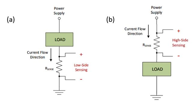
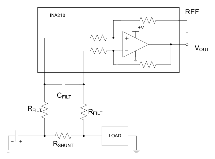
Shunts consume power, under the same I^2 * R law, so we like to make them small (in the milliohms) but their size is directly related to the measureable voltage drop across them, so we want to make them large. There are specialty resistors available that have high power dissipation ratings (around 1-3 Watts is typical), but we are normally left also amplifying their output voltages, to be read i.e. on a microcontroller ADC between 0 -> 3.3v.
Switching current is also typically very noisy and so we filter it as well. Both of these strategies are seen here:
Hall Effect Sensing
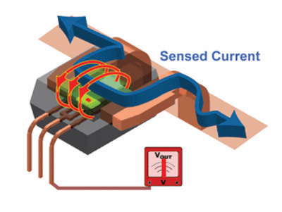
Somewhat more straightforward, hall effect current sensors pass current through a small magnetic loop, and the field is sensed directly using a hall effect sensor.
These are typically more expensive and can be slower. For more, see sparkfun where the image below is from:
Software Current Control
One approach to actually control the current involves a digital control loop, normally implemented in the microcontroller. Here, we would sample our current sensor during the interval where the switch above it is on to measure current,and would apply some control law (normally PID) to change PWM (switching duty cycle) that effectively changes voltage, thus driving more or less current to meet our target.
Hardware Current Control (Chopper Drives)
Chopper drivers are commonplace, i.e. the A4950 (our fav) implements chopper drive to limit current through it’s H-Bridge, as do most stepper driver ICs.
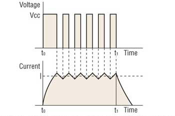
With a chopper drive, control is simple: a hardware comparator watches the top of a sense resistor to measure current. When this current exceeds a set limit, the switches are turned off, allowing current to decay. After a (normally fixed, sometimes variable) time, the switches are turned on again.
Because this is done in hardware, it can be incredibly fast - and does not burden your microcontroller with calculating control outputs. This is a type of ‘bang bang’ control where we simply turn something on when the output is too low, and off when it is too high.
The Low-Side DC Switch
So! To switching. The barebones turn-it-on architecture is the low-side DC switch. Here, we connect one side of the load to voltage, and the other side to ground through a mosfet. Because the source (‘negative’) terminal of the FET is referenced to ground, we can switch it with a logic level signal.
Note that in this implementation I include also a flyback diode (D2) so that when the FET (Q1) is open (turned off) current built up in the load (connected at J2) can recirculate. This schematic also shows a shunt resistor (R5) that allows me to measure current, and an RC filter (C2, R1) that calms that signal. The gate also turns an LED on / off, to indicate the switch status.
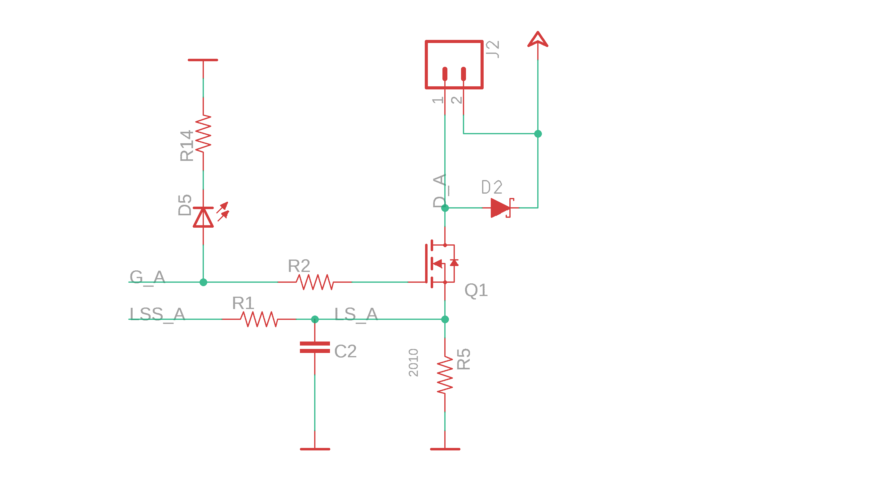
Great for i.e. heaters (resistive loads) or solenoids / relays (single-directional inductive loads). Or driving large LEDs…
Half Bridges
The half-bridge is akin to the totem structures we saw earlier: they can drive one output either ‘high’ (top switch on, connecting the output to voltage), ‘low’ (bottom on, connecting the output to ground), or ‘high impedence’ (both off). If we switch both on, we have a ‘shoot through’ condition where we connect voltage to ground and (probably) destroy the FETs.
H-Bridges
The H-Bridge is extremely common, and is simply an assembly of two half-bridges. This allows us to drive either end of a load to high or low, pushing voltage through in either direction (or none).
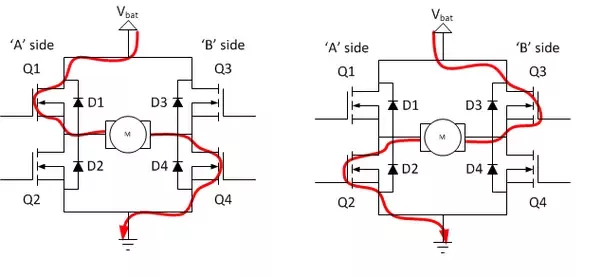
There are recirculating current cases as well, allowing an h-bridge to also recirculate current internally.
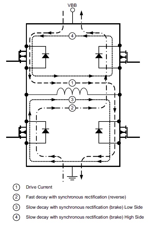
This can become somewhat complex / beguiling, as it depends on dynamic states of the inductor etc, but is important to pay attention to when we get into the nitty gritty. I won’t claim to completely understand it. Recall that FETs have ‘body diodes’ that encourage this behaviour.
Since a stepper motor is nominally two coils (A and B), stepper drivers are typically consisting of two H-Bridges (aka Full Bridges), one per coil. Driving each in succession allows us to ‘commutate’ the motor.
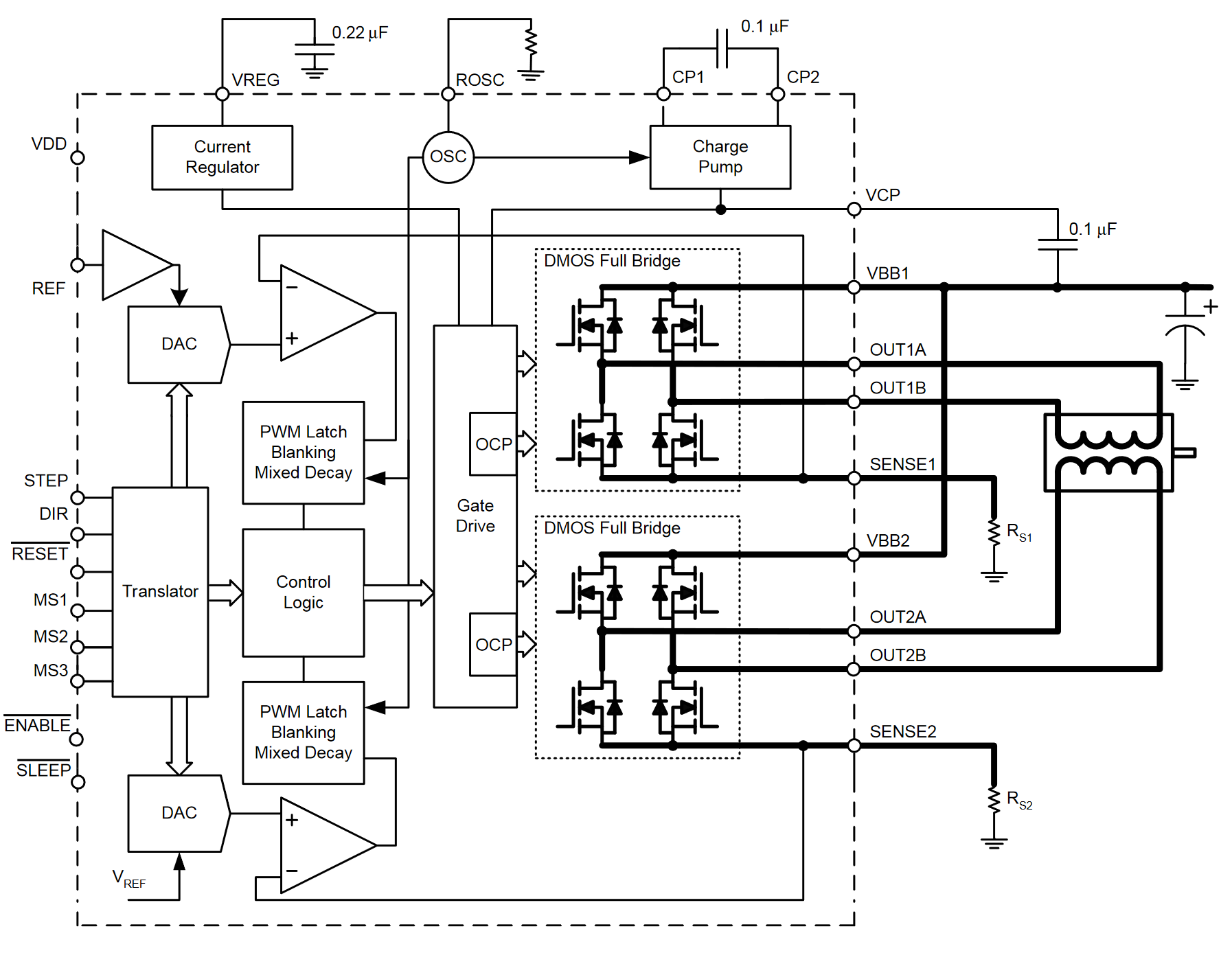
My stepper driver does the same, with two discrete H-Bridges (A4950), both of which implement chopper drives, giving the circuit full control over the magnetic field generated in the motor.
Triple Half Bridges
Brushless motors have somewhat strange coil arrangements: each of three coils are connected through a central node. This is known as a ‘wye’ connection:
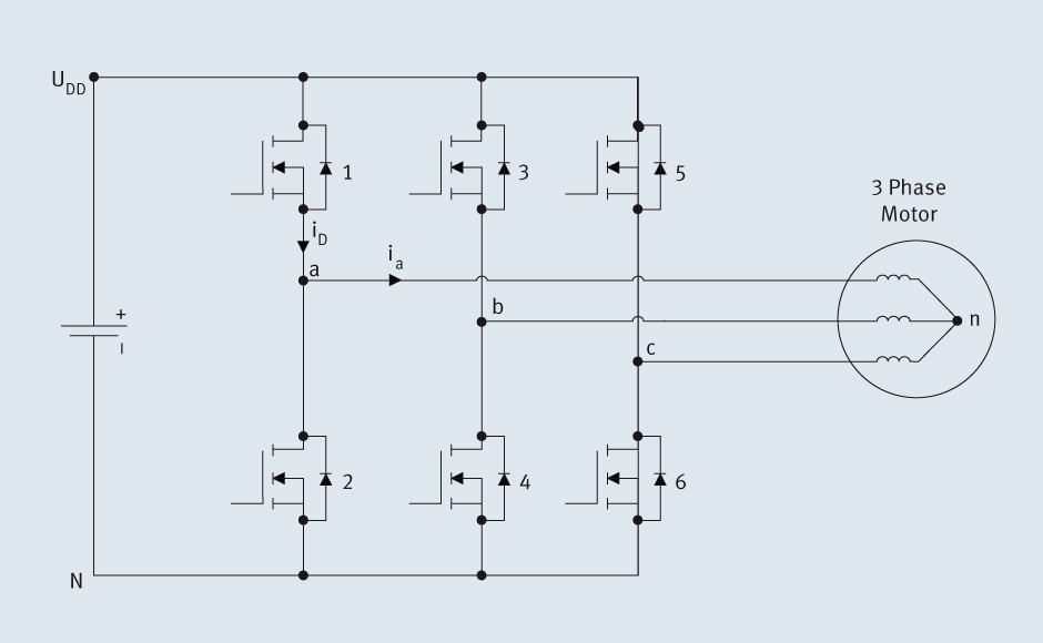
from this detailed write-up on BLDC drive
Here, we drive current ‘in’ to one motor lead, and ‘out’ of another. In the section on commutation, we’ll look at this in more detail.
Dual Active Bridge (DAB)
The Dual Active Bridge is the new hotness in power conversion, especially applicable to solid state transformers where we want to pass current in two directions (from the grid, or back to it).
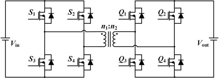
Here, we can imagine dumping current into the coil, or retrieving it from the coil, in either direction. Since we are actively switching both coils, we can ensure changing current (and changing magnetic field) to do the transforming or energy handoff. Basically, we can go DC -> AC -> DC seamlessly. Losses only amount to the FET’s RDSon!
Gate Driving
Now! Recall that FETs require energy to switch on. As discussed earlier, a FET typically performs better when it’s gate voltage (Vgs) is large (10v is typical), while our logic signals available from the microcontroller are 0-3.3v or so, and are current limited.
Recall also that we switch these at high frequency, normally 10kHz or larger. Given a FET’s gate capacitance (how much charge is stored in the gate before it switches on), and our switching rate, we can calculate how much current (rate of charge) is required to effectively switch the FET. This can be surprisingly large, in the single digit Amps, while a micro will deliver ~ 35mA only.
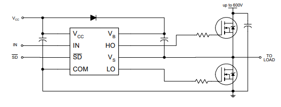
So! We have gate driver ICs, themselves small collections of FETs (normally one half bridge per FET-gate) that do the lifting.
Removing Heat
Power electronics generate heat! Removing it effectively makes the difference between a performant circuit and a faulty one.
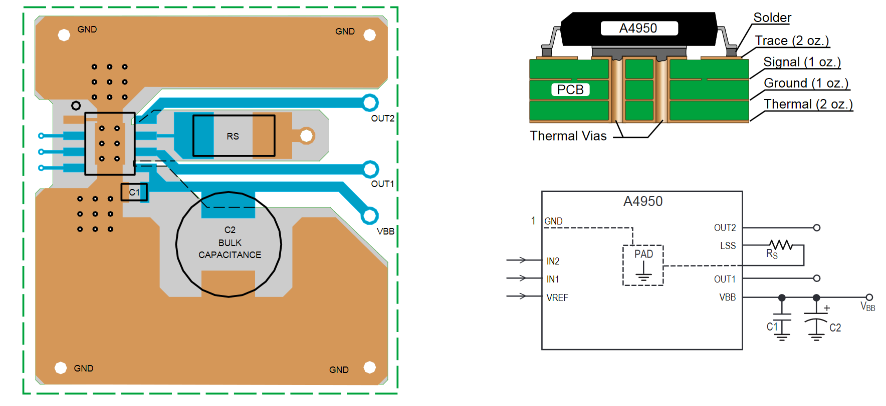
Simple consideration of PCB layout can help a great deal: most power ICs (PMIC) include some big metal land that can be soldered to a large surface of PCB copper to encourage heat dissipation from the part, as in this note from the A4950 datasheet:
We can also consider the extreme case of power management in an electric car, noticing the efforts made to (1) carry power through monster conductors (bus bars, solid copper ribbons) and (2) remove heat with i.e. liquid cooling delivered directly to the FETs.