Commutation
I wanted to add a note on how this all comes together when we deal with power electronics. Note that the field of power electronics is typically more interested in i.e. efficient voltage regulation (this effects i.e. how long your phone battery lasts) but in machines land we are typically interested in turning motors around.
So, commutation is how we do that. In brief, this is how we manipulate currents in inductors to build magnetic fields in motors to ‘pull’ the motor-rotor around. Properly ‘commutating’ a motor means properly aligning this magnetic field to produce maximal torque.
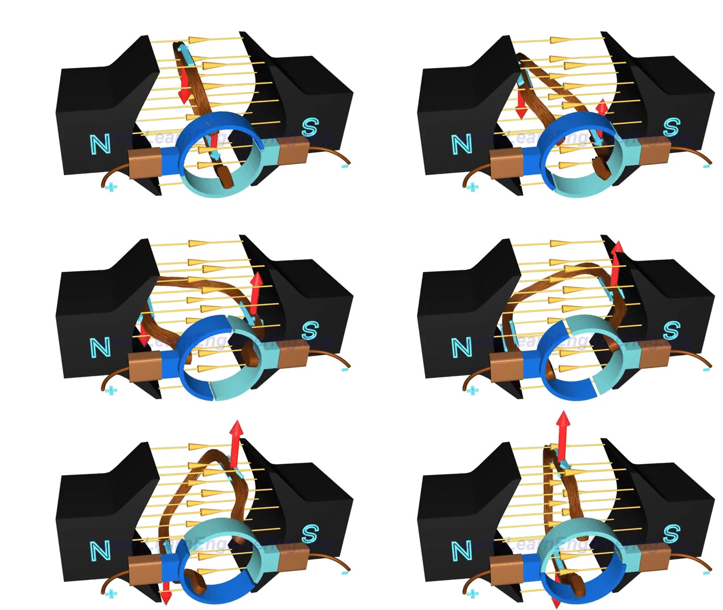
DC (Brushed) Commutation
The beauty of the brushed motor is that we don’t have to commutate it: the brushes do this for us: they are arranged so that power is switched in alternating directions through the motor as it spins.

BLDC Commutation
While the circuits are more complicated, brushless motor commutation is in a way simpler than i.e. stepper motors.
The best way that I have found to think of this is to consider that the rotor (which spins) has a static magnetic field generated by i.e. rare earth magnets. This has a direction, a vector we can think about. To ‘pull’ the rotor around, we want to exert a magnetic field with our stator (the magnetic armature / part that is static) which is 90 degrees out-of-phase with the rotor. The magnetic fields want to line up (this is their minimum energy state) and so we attract the rotor along, at each step (ideally) measuring the position of the rotor, calculating desired currents that will place a magnetic field 90 degrees away from it, etc. Kind of like leading the horse with a carrot.
Sinusoidal Commutation / Field Oriented Control

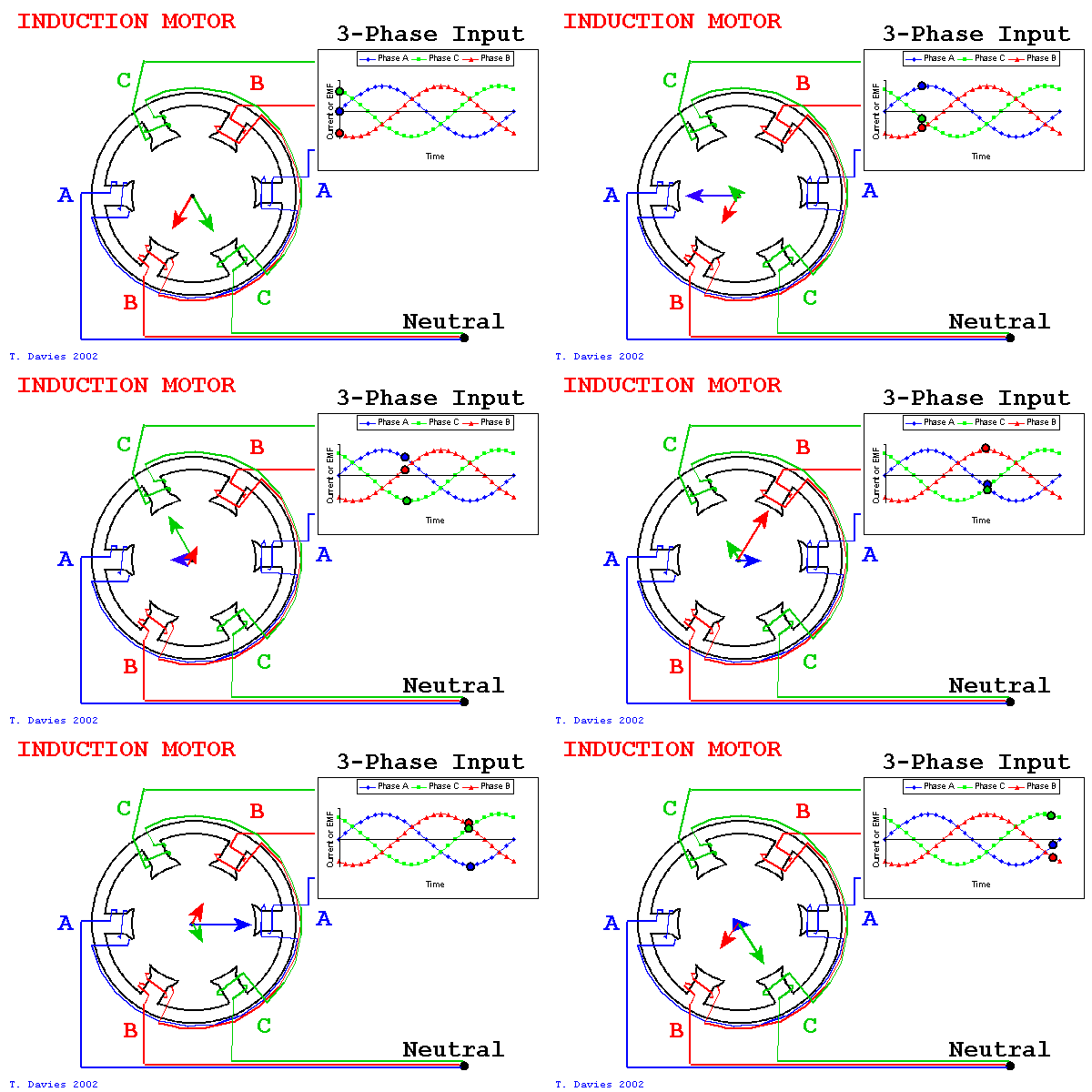
With sinusoidal commutation, we control all three phases simultaneously, we can consider that each has a kind of component vector that contributes to the overall field’s ‘direction’.
The output of these systems is AKA ‘space vector pwm’ - PWM signals that put a ‘vector’ of magnetic field in space. However, our ‘voltage vector’ does not equal our ‘current vector’ (or actual field vector) - and so Field Oriented Control adds the additional step of closed-loop current control into the mix.
This uses some space transforms that can seem perplexing at first. They are in place to effectively reduce the required bandwidth of our current controllers… This is a whole adventure, I’m just providing pointers here, so I apologize for the brevity. Enter the rabbit hole at your own risk.
Six Step Commutation
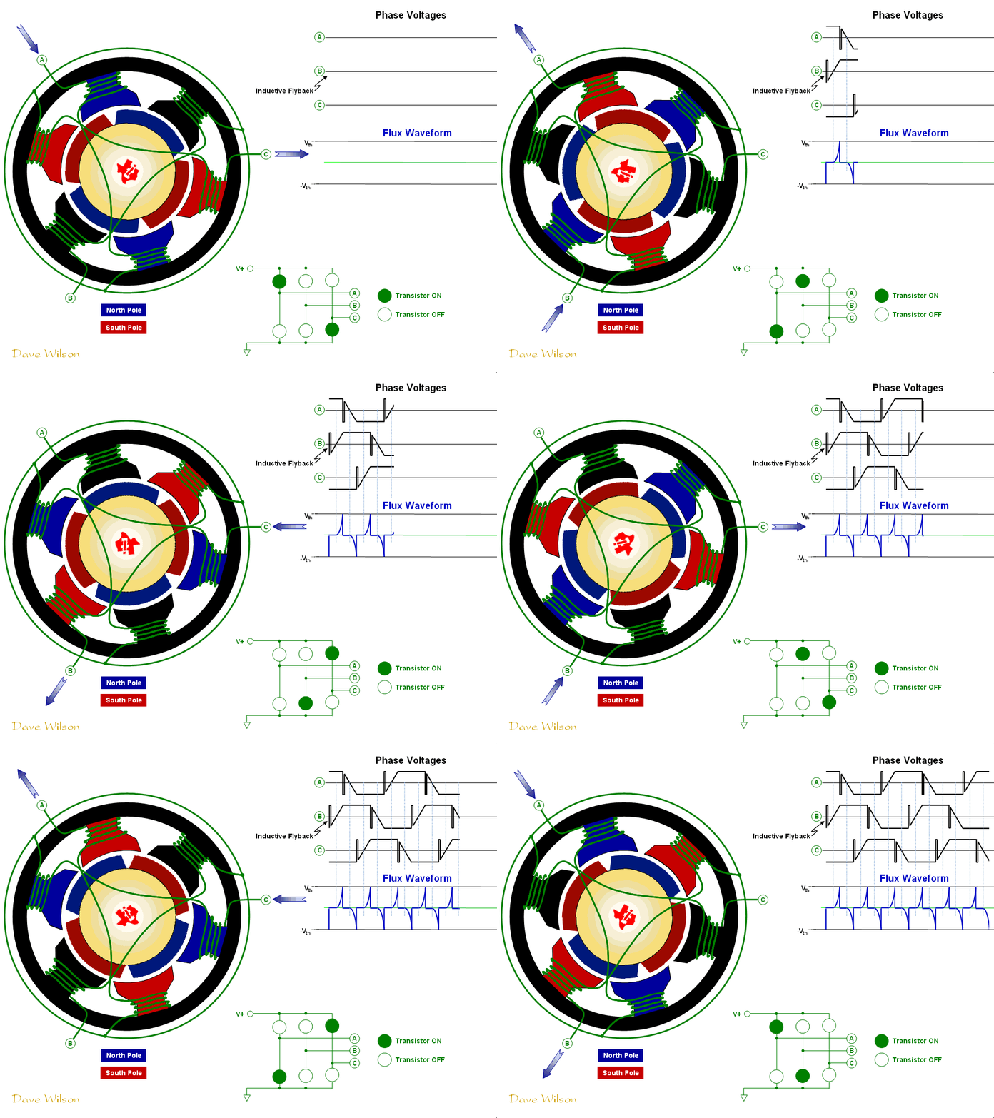
The more common approach is ‘six step’ commutation, below:

This has the advantage of being simple: we connect one of the half-bridges to ground, and another to voltage. This drives current through two of the coils simultaneously (so it is, also, slightly less power dense). We can do this easily in hardware with hall switches, something which I am not going to go into at length: basically, hall sensors measure the rotor position by measuring the position of the rotor’s magnetic field.
Back EMF (BEMF) Sensing
In six-step control (above) we have a ‘sensorless’ means of measuring the rotor position (but only when it is already swinging) by meausring the ‘back elecromotor force’. Basically, the coil that is off becomes a rotor position probe: the rotor’s magnetic field is driving voltage into it. It’s voltage (which we can measure with the microconroller) swings from low to hi (or vice-versa) and when it hits the center of our drive and gnd voltages, we know the rotor has made if half-way through one step. We then set a timer that expires when the rotor has completed the step, and continue the commutation.
Sensorless Sinusoidal Commutation
Well! Consider that we can only sense back EMF when a coil is not actively switched. How, then, would it be possible to do so when we are driving a full sinusoid into each coil, as above?
Recall that each of these sinusoids is actually composed of many smaller switching cycles: our duty cycle into each coil is rarely 100% on. So, we can sense ‘free’ coil voltage during PWM off times.
Sound difficult? Correct. It requires very low-level manipulation of microcontroller peripherals (to i.e. only sample voltage sensing ADCs when voltage driving PWMs are low) and really good input filtering / state estimation.
There is a ti doc on the topic, and a microchip app note.
Stepper Commutation
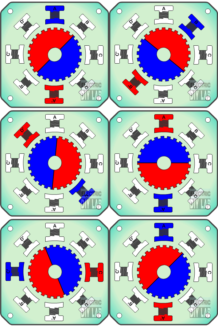
Stepper commutation is a little bit more straightforward.

However, it’s complicated by the stepper motor’s internal geometric complexity. The most common type we find is the ‘hybrid stepper’ which is part variable reluctance, part permanent magnet motor.
Stepper Field Oriented Control
I doubt that I have time for it here, but suffice it to say that a stepper can be treated like a BLDC, and driven with fully sinusoidal (and closed loop) field oriented control. This is what I have developed for my stepper driver: the controller senses rotor position, and (given a calibration table) can quickly calculate outputs that generate a magnetic field which is 90 degrees offset from the rotor’s static field.
I wrote a big ol’ log on how I sorted this out including code snippets etc.
This results in some great motor performance: