Active Sensing
Unlike the 3D scanning methods that physically contact the object to read the geometry, this page outlines scanning methods that capture the shape of the object using light sources and without contact. Advantages of using light include capturing data without physically touching the object and speed. The scanning methods are sorted by the object that each scan method is used for.
Laser Scanning Confocal Microscopy (LSCM)
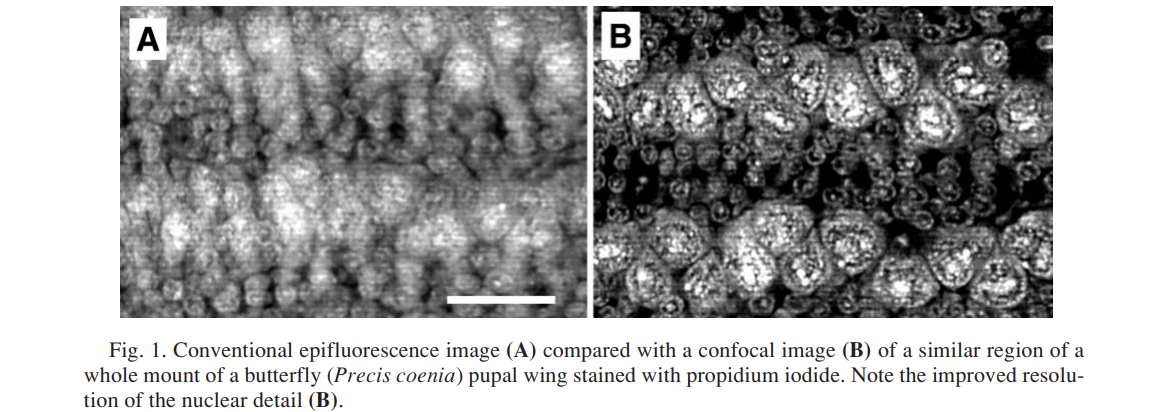
The major application of LSCM is for biomedical sciences, as it is capable of capturing a maximum resolution of 0.2 micron meters, which is better than a conventional widefield light microscope.
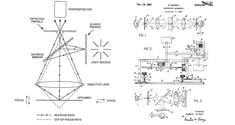
Basic configuration of confocal systems and original idea(Marvin Minsky)
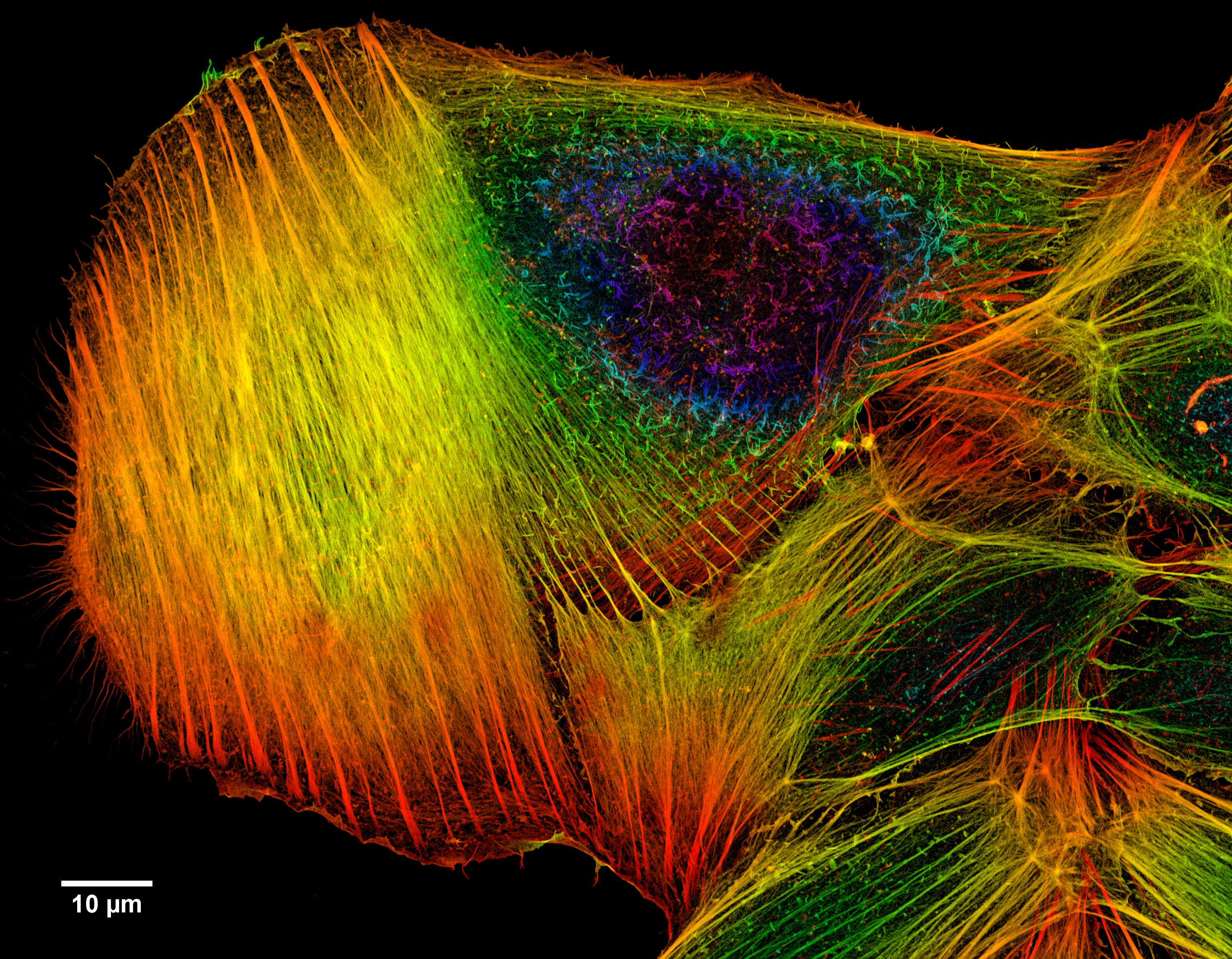
High resolution of Cancer cell
With conventional microscopes, fluorescence in the specimen on non-interest focal planes interferes with the image of the specimen on the focal plane, resulting in reduced resolution of the image.
-
Applications
Life Science, semiconductor inspection, material science. -
Reference
Principles and Practices of Laser Scanning Confocal Microscopy
Introduction to Confocal Microscopy(Youtube video)
Memoir on Inventing the Confocal Scanning Microscope
Line Laser Scanning
based on a trigonometric calculation
The line laser scanning process scans objects by reading the location of reflected laser light on the object’s surface. Often, the scanning devices will have one or two lasers and a camera. The facing vectors of the laser and the camera are not parallel to each other. The angle between the two vectors and distance between the laser and camera is used to compute the location of the reflected laser light.

Along with the device, software is needed to process the captured image to extract the location of the laser. In DIY versions of the scanners, software lets users manually modify contrast and brightness of the taken photos for image processing. The software generates 3d objects using the XY coordinate of the laser on the captured image(pixel location) and the distance and angle between the laser and camera.
Line lasers can only read the object’s location where the line laser is reflected, which means only one section of the object is visible. So this scanning technique uses an accompanied gantry machine, cnc, or rotating platform to locate the object at different angles or positions to capture the geometry from multiple directions.
-
Advantages
Low price, fast scanning( ~10min), precision( ~0.01mm) - Disadvantages
It is difficult to scan objects that do not reflect lights well, such as objects with glossy, shiny, and trasparent surface surfaces or ones with matte red or black coloring. To overcome this, scanners use different colored lasers, including blue. Small ranage - Usage
Automated inspectionReverse engineering
- Machines
MakerBot:Digitizer($750), Matter and Form($770), FabScan($200) - Reference
Structured light
projecting known patterns (such as bands of light) from projector and triangulation
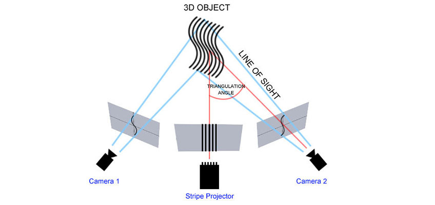
- Light patterns
Indexing, sequence of strips 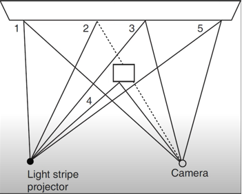
Strips 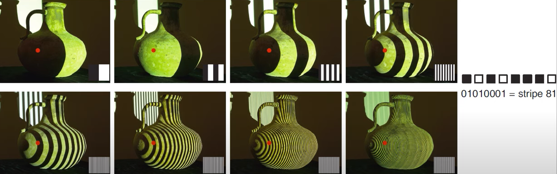
Uique strips 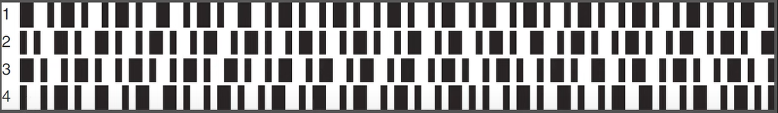
Uique strips (colored) 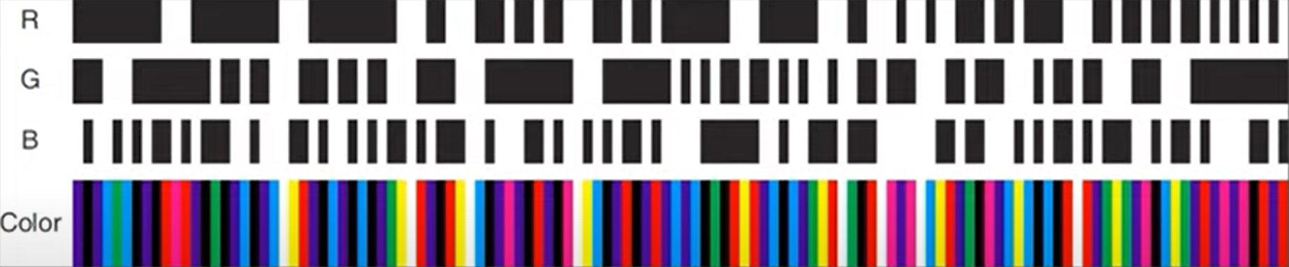
Many others 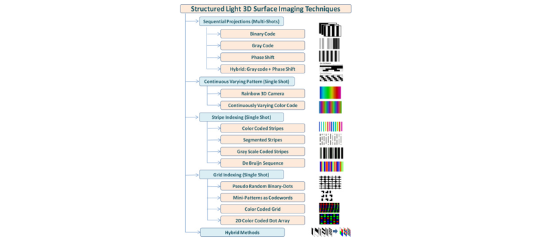
Structured-light 3D surface imaging: a tutorial
- Usage
Reverse egineering, manufacturing, healthcare, education, art design -
Machines
Artec Eva ($20,000) Structured Light Pro S3(David Scanner)($4,400), Polyga - Reference
From HTM2018
SIGGRAPH 2009 Course,Note From Laser Lines to Structured Light Laser Scanner vs Structured Light Scanner How Do Structured-Light 3D Scanners Work?
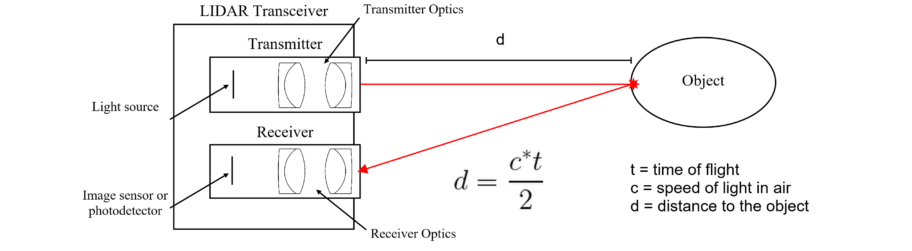
Time of Flight
The core idea of Time of Flight (tof) methods is to send a wave and measure the time it takes to bounce off the target and come back. Knowing the propagation speed of the wave, the distance is easily deduced. The wave could be of any form, but the currently most popular type is light waves, as we now have electronics able to detect these brief timings.
LiDAR
In LiDAR, a laser pulse is sent and bounced back to the sensor. A detected pulse provides a distance measurement in the laser direction. To obtain a full 3D map of the surrounding, the laser needs to rotate to cover a wide variety of angles. The density can be tuned at the expense of a longer capture time.
LiDAR has become popular in the car industry, as it is reliable at long range too and is not subject to interference from sunlight. The other main application is architectural scanning, for which the accuracy is far sufficient. In this case, it is often necessary to combine scans from several locations. This creates visible viewing rays in the point cloud distribution.
Time of Flight cameras
Time-of-Flight cameras is similar to a LiDAR setup with a single emitter and millions of receiver: each is implemented as a CMOS pixel with a demodulator. In this case, we don’t use pulses but rather modulate an IR LED with a sine-like profile. This lets the pixels estimate the phase shift of the received sine-wave.
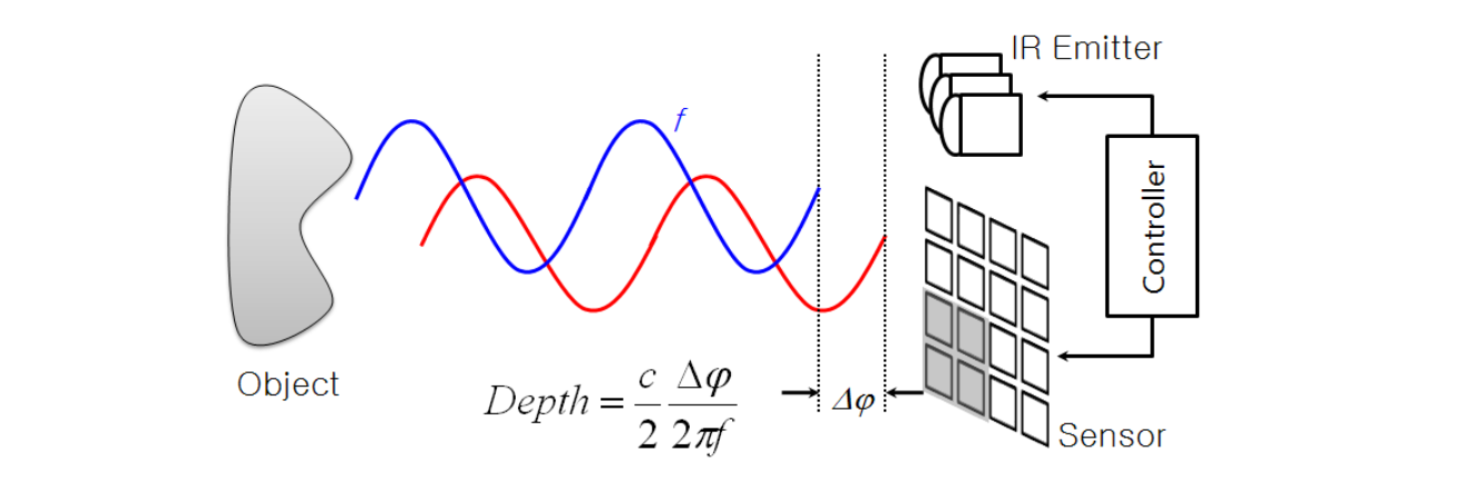
The phase shift can be measured in several ways, but is typically obtained from 4 amplitude measurements. The strength of the signal is also retrieved, which is important for noise estimation.
ToF cameras are popular in gaming and realtime applications as they provide a depth map in a single capture, up to 1024x1024 pixels for the Kinect V4 sensor.
One common issue for complex scenes is multipath, where the IR light bounces from a second object before returning to the sensor. This typically produces rounded corners with loss of details. Another issue is flying pixel, occuring on edge regions (mixing of foreground and background signals).
Here is a point cloud acquired with a Kinect V2 with no post-processing, which can be done with libfreenect2. By default the Windows SDK applies a bilateral filter to smooth the depth map, but raw data is still useful for research on noise removal.
Here is a Kinect V4 scan straight from the sensor. Note that there it includes some post-processing that cannot be disabled: