Week 1: Project Description
The machine is built to automate the central dogma of molecular biology, the idea that DNA encodes the instructions to assemble proteins and other higher order structures. To accomplish this, I am building a iquid handling robot.
Week 3: System Preliminary Design
System Preliminary Design
To automate the central dogma of biology, we will need to translate our DNA into proteins, there are
many ways of accomplishing this
but to keep things simple we will use a fairly standard approach of cell based protein
expression.
The steps are as follows:
a) insert vector into plasmid (outside the scope of this work)
b) introduce plasmid into cells using a technique like electroporation
c) incubate cells for an extended duration, often overnight
d) lyse the cells to yield functional proteins
The machine will be responsible for automating some of these steps, what's unique about this machine is that it interacts with micro-arrays of proteins or DNA. Each micro-array can accomodate in excess of 384 reactions in a 25mmx25mm area while typical well plates would require 127mmx87mm. As a consequence, I could parallelize up to 10k simultaneous reactions in my bench-top tool, the same number of reactions that would be capable of a well equipped biology lab.
Week 5: Systems Engineering Design
redacted
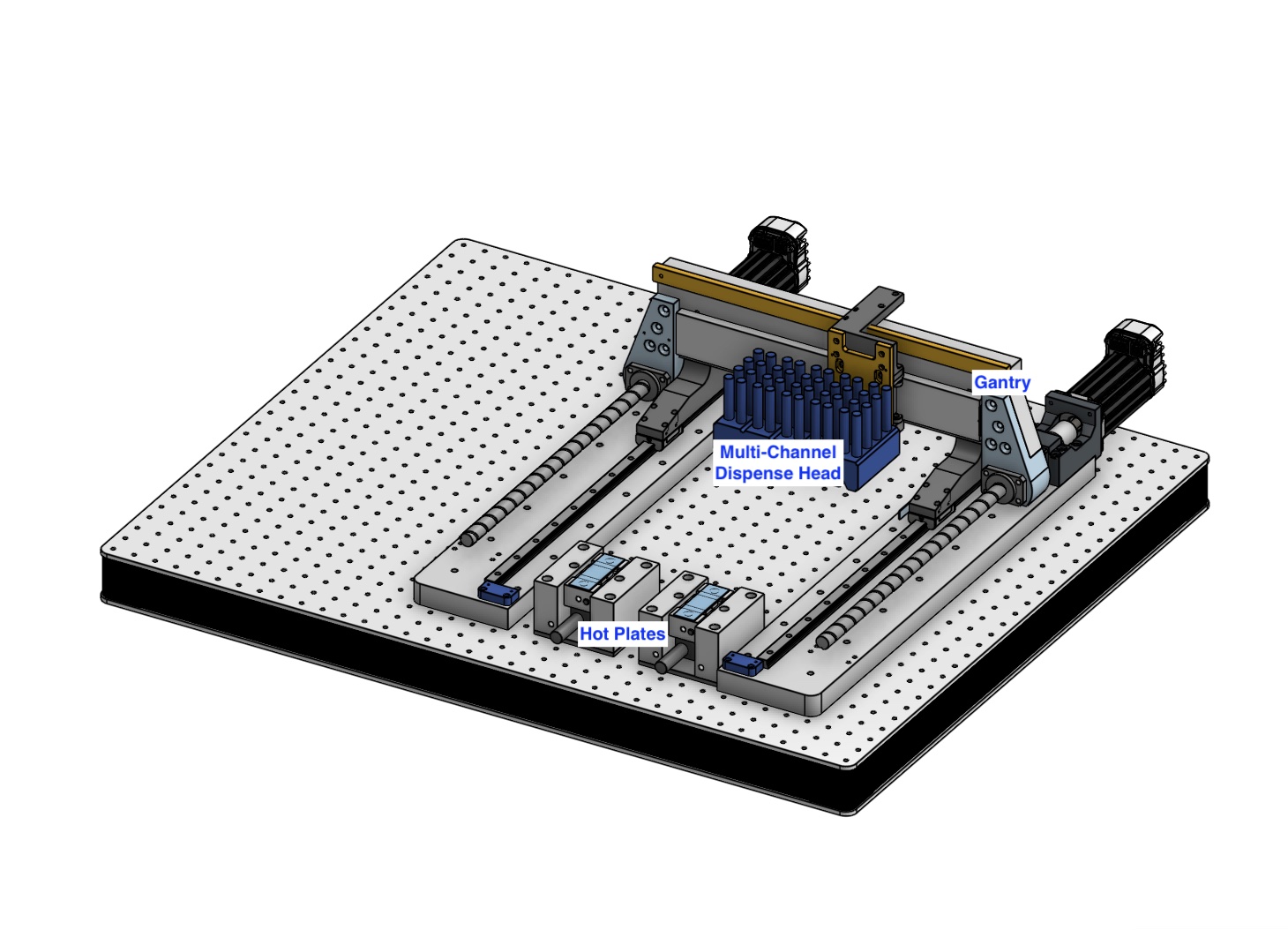
Week 7: Gantry Accesories, 1
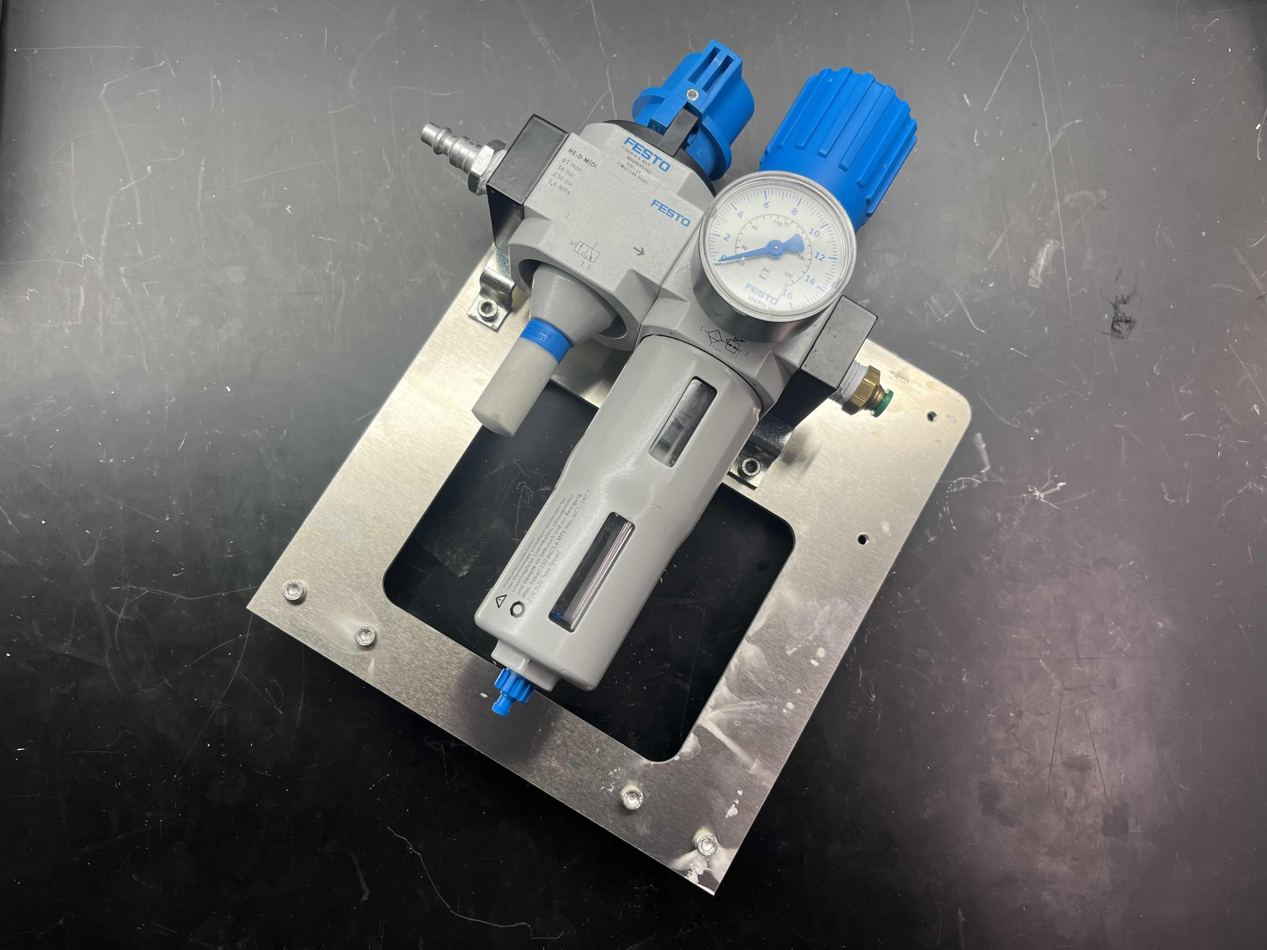
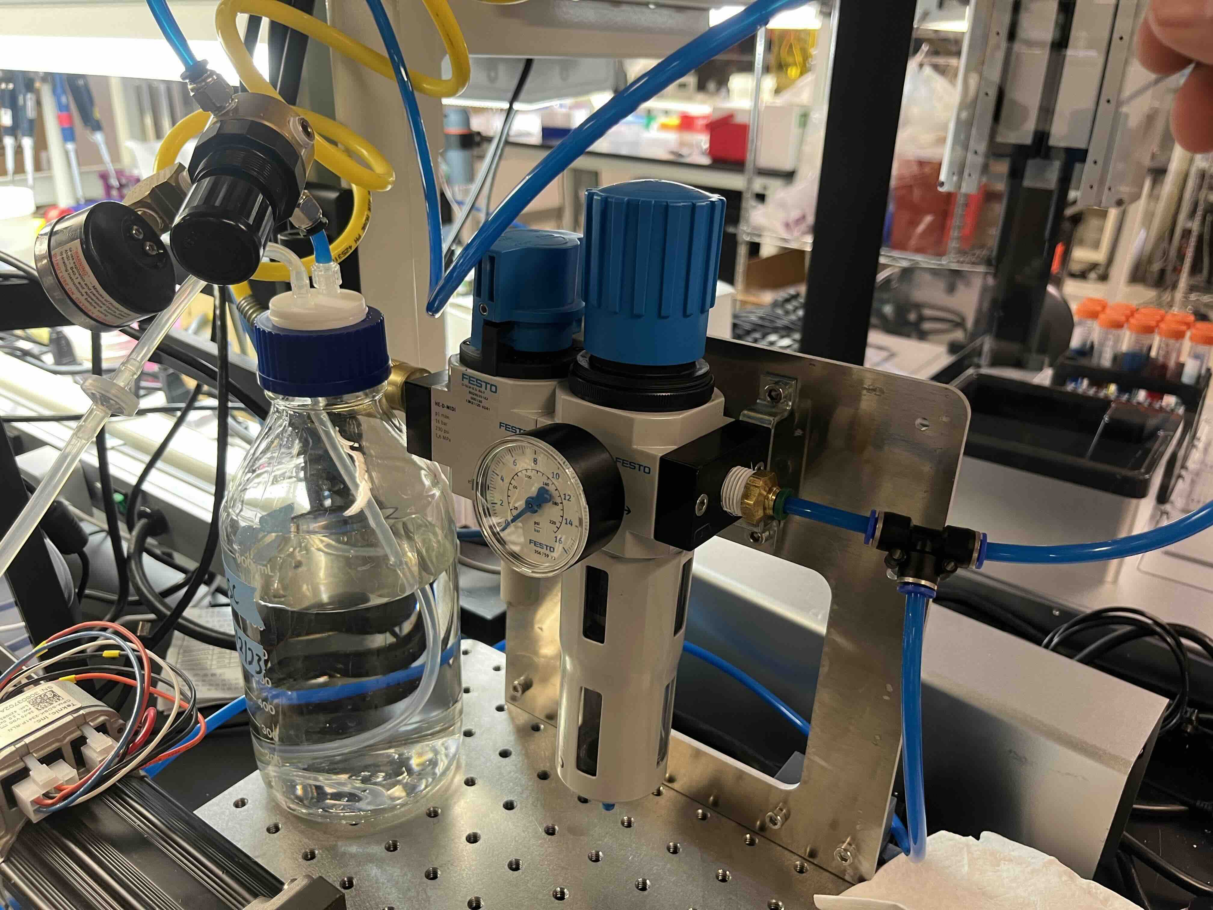
Big week here, I switched out the previous H2W STS-0620 6lb Single axis linear stepper motor for its air bearing sibling, the H2W STS-1220, with 10lb of force! This took a TON of work as I had to run air lines through the shop, secure a valve manifold, and take care of all plumbing.
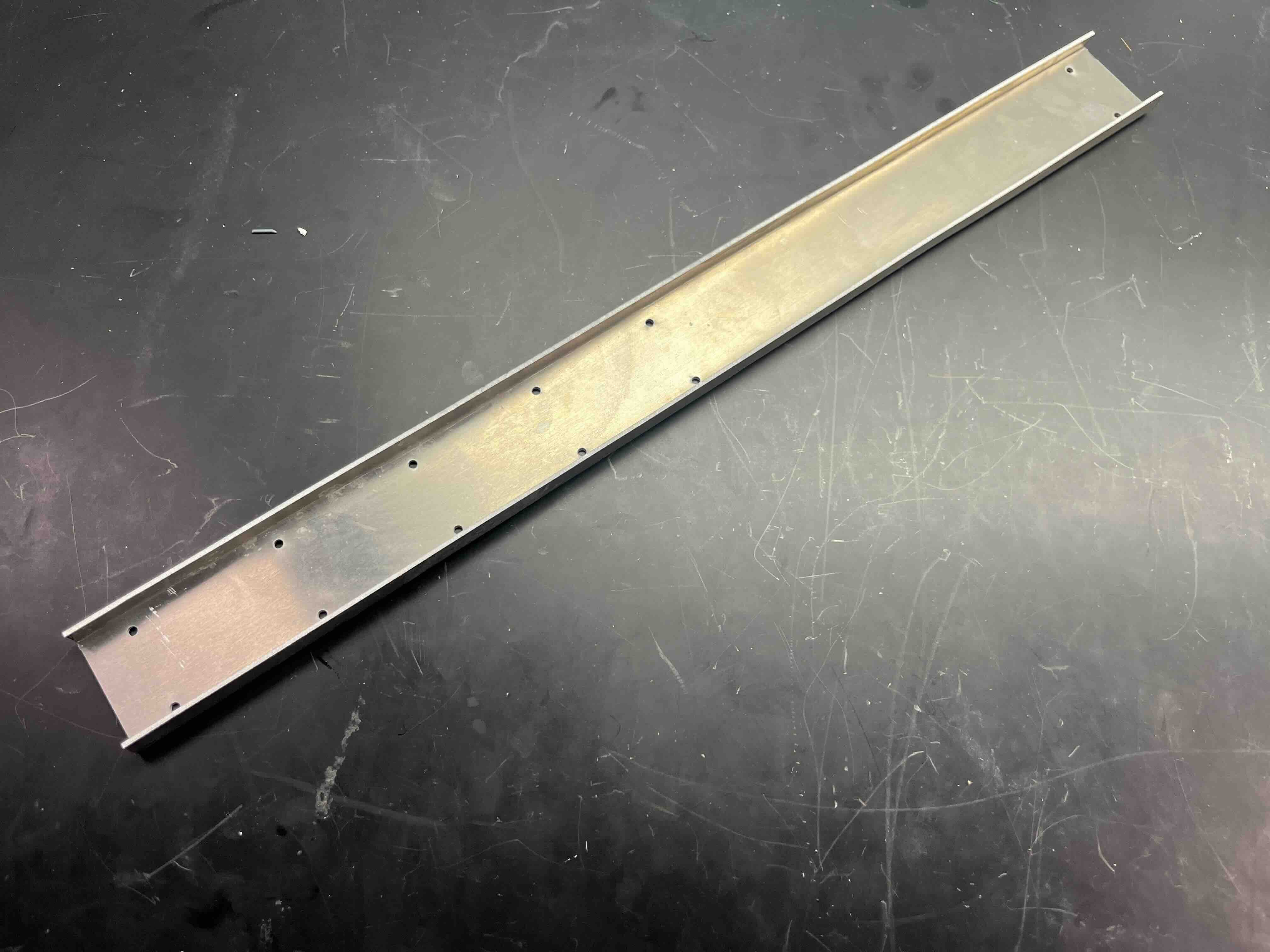
A little waterjet here, a little waterjet there...
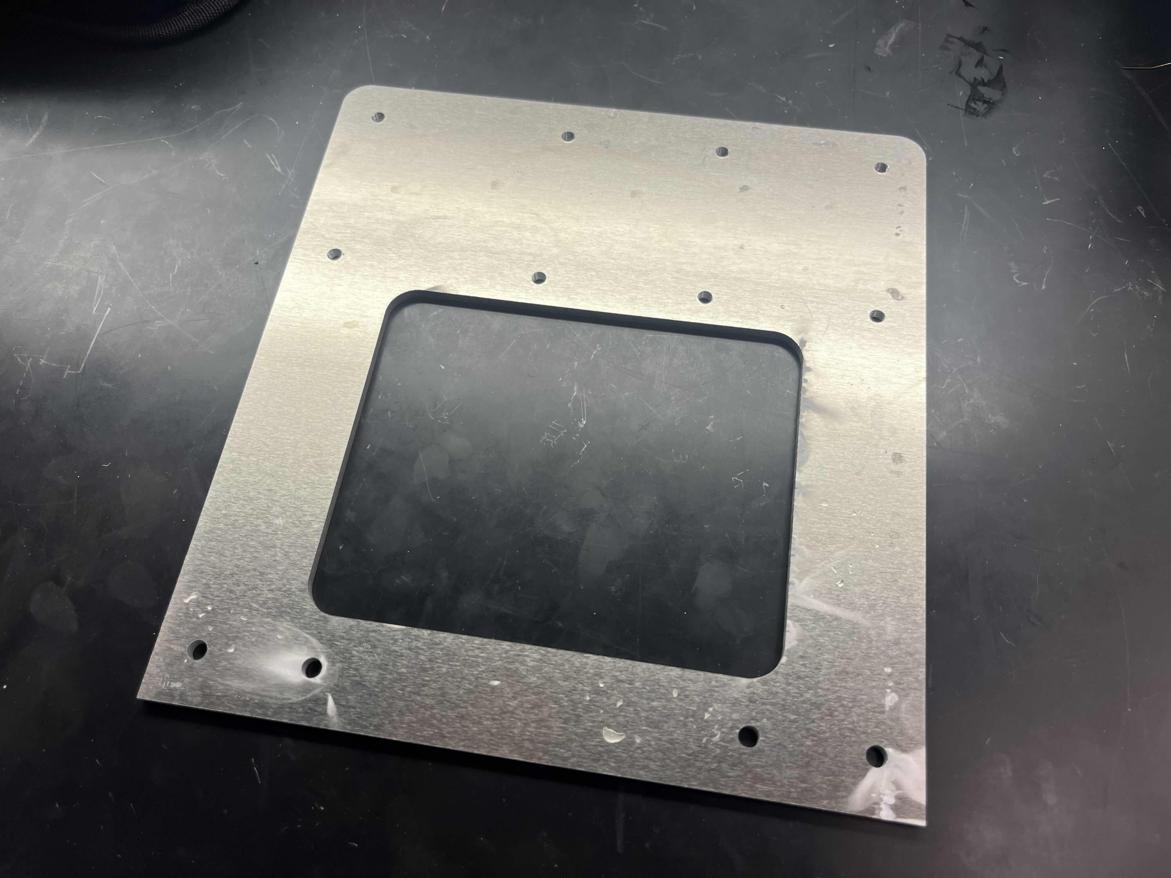
Spent some time waterjetting a new faceplate for the larger air bearing motor (look at countersinks!!)
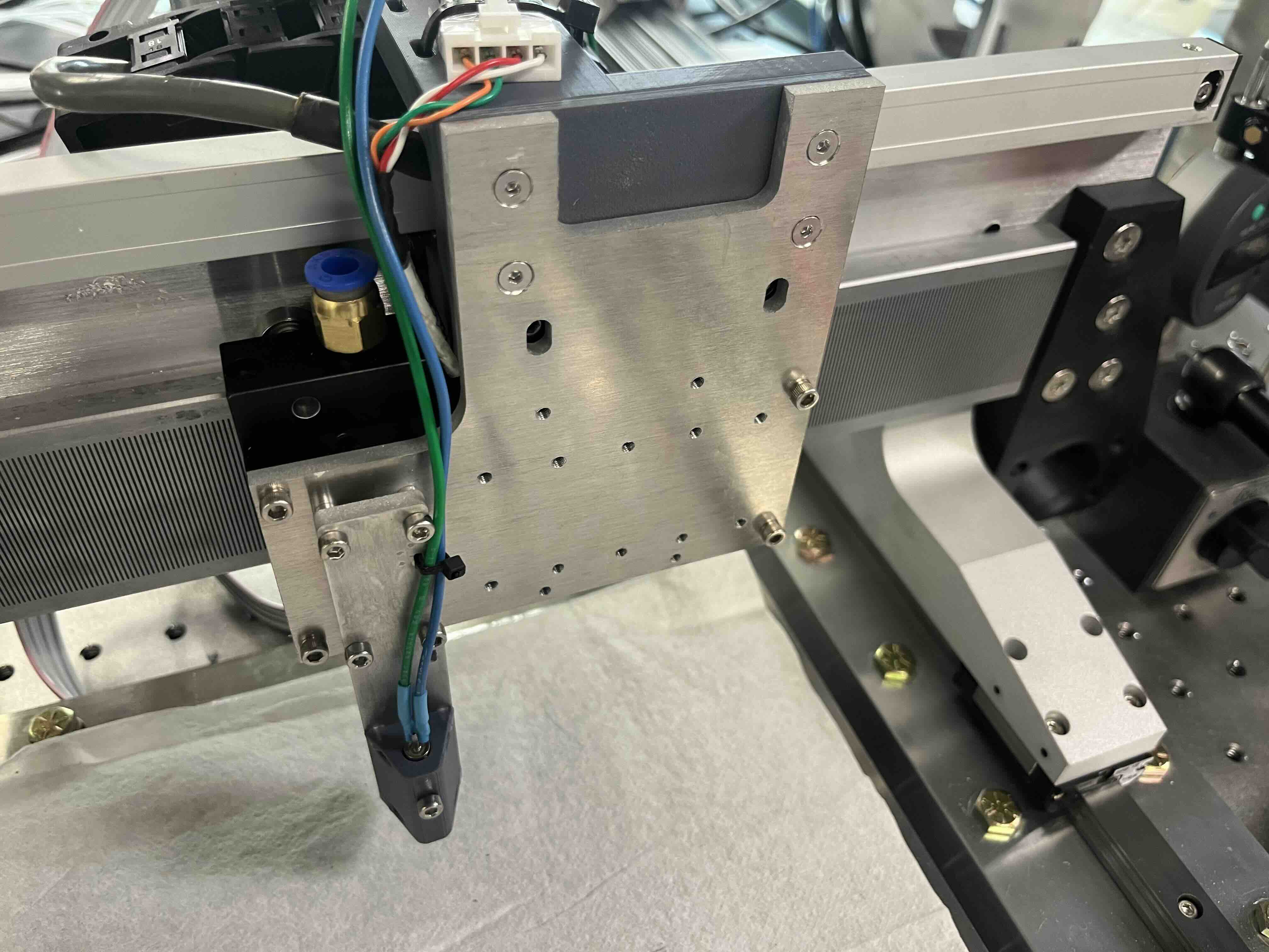
Then I got started on the code, what's appealing about the linear stepper motor is that it can be driven essentially like a normal stepper motor. When I won this auction on eBay it included a linear encoder, precise to 1µm so I decided to try out the Duet 1HCL's built in closed loop control method. To implement this I had to turn on the follow instructions in the configuration:.
    ; Duet 3 MB6XD
    M569.1 P1.0 T2 C12728 R20 I0 D0.2  ;; physical drive 1.0 goes forwards, X 12728 counts per step
    M569 P1.0 D5 S1                    ;; configure the motor on the 1HCL as being in closed-loop drive mode (D4) and not reversed (S1)
    M917 X50                           ;; set the closed loop axis holding current
Subsequently, I was able to use the tuning interface to loop through P, then D, then I values in that order. Eventually converging on PID values of 20, 0, 0.2. The performance difference was imperceptible however, I wonder if this would make a bigger difference if I had a heavier load. Overall, I'm not very impressed, as this forcer should be precise to less than 5µm, especially with a closed loop controller.
Week 9: Gantry Accesories, 2
The aluminum parts arrived, the uprights were installed and worked great, but the supplier that provided the ball screw nut holders provided parts that came in WAY out of specification.
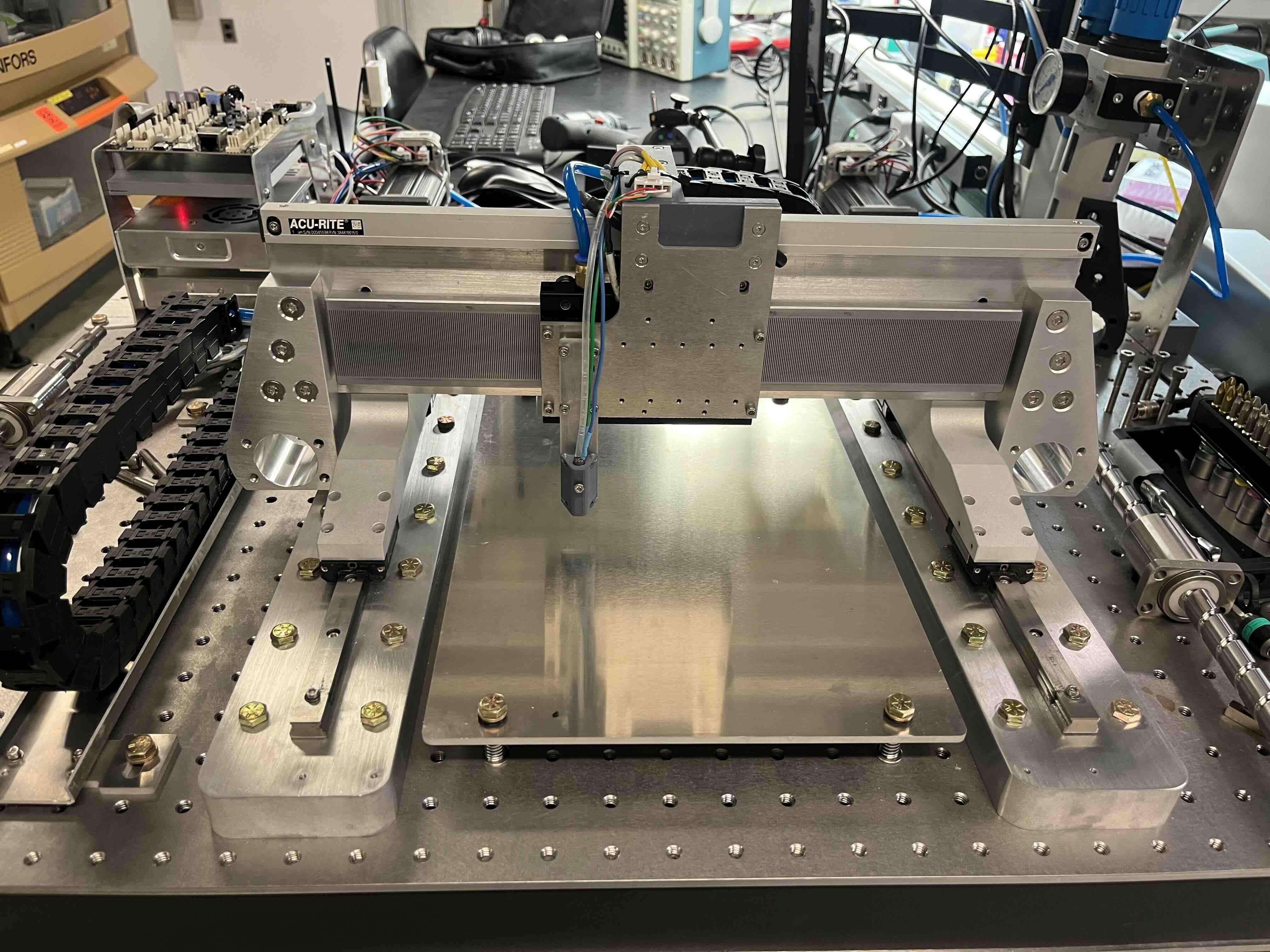
In the meantime, I built a cheeky cable guide, and a base plate for testing (more waterjetting!)
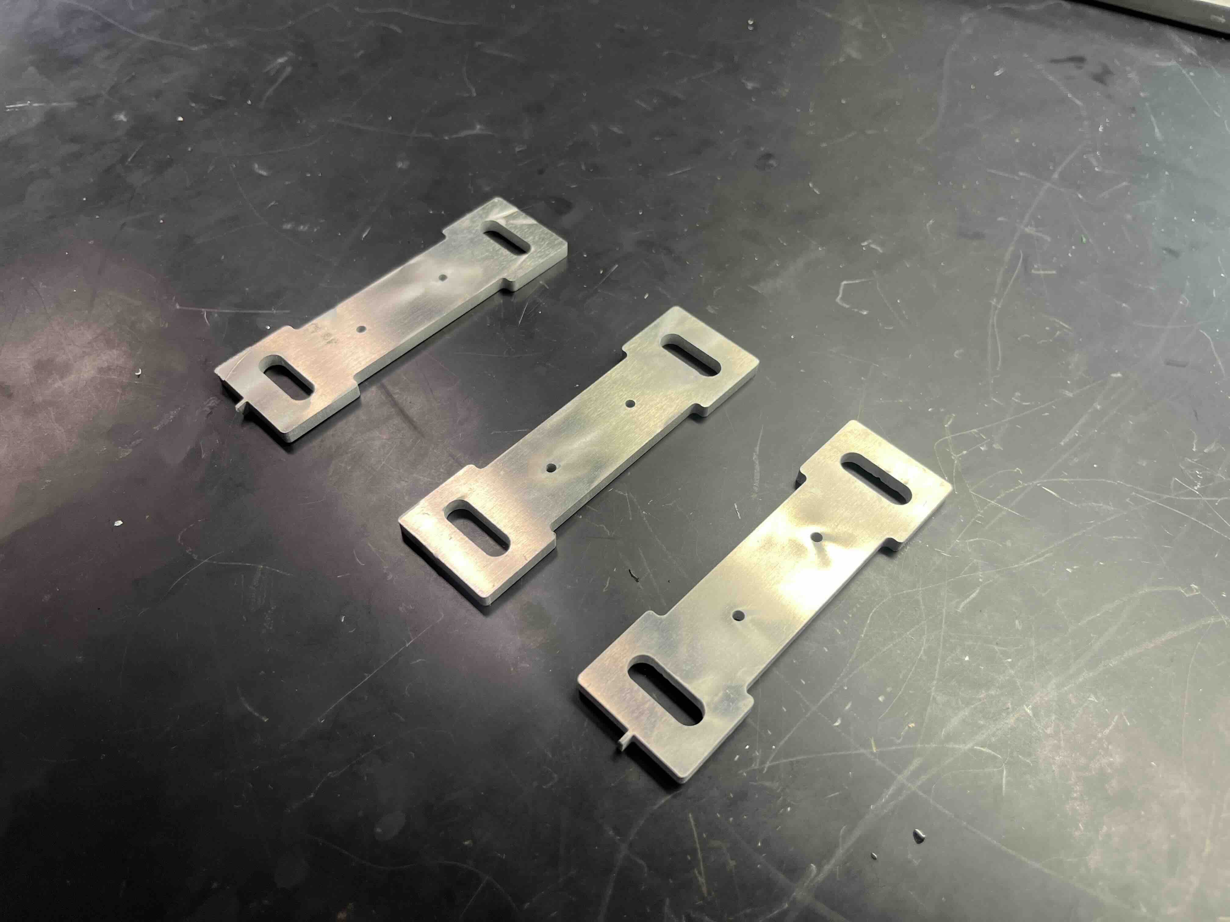
Looks nice, is useless. At least the cable guide is lovely (pictured on the left).
Week 10: Solenoid Driver + Comms
I went back to the plastic parts (just for now, don't worry) and reassembled the machine.
Additionally, I got started on the solenoid driver. To save a bit of time, and to further understand the machine control requirements, I elected to move
forward with the modular things low mosfet
board.
I found that the Duet3D mainboard was able to generate waveforms with a minimum resolution of 1ms, but
the solenoid needed a 350µs pulse, so I needed to add a bit of logic to the receiving board.
To do this a pulse was generated by the mainboard, with a custom Macro. When I call M711, the following code is run, where S is the parameter defining volume.
; Duet 3 MB6XD
My initial implementation relied on signal interupts on the RP2040 to detect the rising and falling edge
of the waveform, but this was rife with issues as there was a significant amount of noise propagating
through the control wiring. After beating my head against the wall, redoing the wiring with a shielded
ethernet cable (thanks Cedric!), and generally going to extreme yet fruitless measures like sorting
pulse widths in 10µs incremements, I rewrote the code to read the signal pin as fast as possible,
and to assign all read values to a buffer. Once at least half the values of the buffer had changed
from the previous state, a flag would be set to indicate that the state was either HIGH or LOW. This state
change signaled a measurement to take place using the ticks_us() library.
from machine import Pin, PWM, Timer
from time import sleep, sleep_us, ticks_ms, ticks_us, ticks_diff

# constants
spike_duration = 0.23  # spike duration, ms
duty_percent = 12.5  # percentage of duty cycle

# calculations for timing
sd_math = int(spike_duration * 1000)

# establish pins
led_pin = Pin(27, Pin.OUT)
sol_pin = Pin(29, Pin.OUT)
trg_pin = Pin(28, mode=Pin.IN, pull=Pin.PULL_DOWN)

# duty cycle calculation
hold_duty = round(duty_percent / 100 * (2**16 - 1))

# PWM setup
pwm_led = PWM(led_pin, freq=1_000_000, duty_u16=0)
pwm_sol = PWM(sol_pin, freq=100_000, duty_u16=0)

# buffer for pin states
state = 0
old_state = 0
state_buffer = []
buffer_size = 20  # length of buffer for averaging, REMINDER: this is a time delay
start = 0
count = 0
testDuration = 0
old_testDuration = 0

def update_buffer():
    global state_buffer
    state_buffer.append(trg_pin.value())
    if len(state_buffer) > buffer_size:
        state_buffer.pop(0)

def check_pin_state(old_state):
    global state_buffer
    if len(state_buffer) == buffer_size:
        if state_buffer.count(1) > buffer_size // 2:
            if old_state == 0:
                print("rising")
            return 1  # Majority is high
        elif state_buffer.count(0) > buffer_size // 2:
            if old_state == 1:
                print("falling")
            return 0  # Majority is low
    return old_state #  this is annoying, and necessary.

print("Initiate runtime")

try:
    while True:

        update_buffer()
        old_state = state
        state = check_pin_state(old_state)
        if state == 1 and old_state == 0:
            print("start counting")
            start = ticks_us()
        elif state == 1 and old_state == 1:
            pass
        elif state == 0 and old_state == 1:
            print("stop counting")
            count = ticks_diff(ticks_us(), start)
            print(count)

            print("spike")
            # spike, 100% duty cycle
            pwm_led.duty_u16(65535)  # set the duty cycle of the led
            pwm_sol.duty_u16(65535)  # set the duty cycle of the solenoid
            sleep_us(sd_math)

            #print("hold")
            ## hold, x% duty cycle
            #pwm_led.duty_u16(hold_duty)  # set the duty cycle of the led
            #pwm_sol.duty_u16(hold_duty)  # set the duty cycle of the solenoid
            #sleep_us(int(count/10)-sd_math)

            # low, 0% duty cycle
            pwm_led.duty_u16(0)  # set the duty cycle of the led
            pwm_sol.duty_u16(0)  # set the duty cycle of the solenoid
        else:
            # low, 0% duty cycle
            pwm_led.duty_u16(0)  # set the duty cycle of the led
            pwm_sol.duty_u16(0)  # set the duty cycle of the solenoid


except KeyboardInterrupt:
    print("Interrupted by keyboard")

finally:
    print("Purging resources...")
    pwm_led.deinit()
    pwm_sol.deinit()
    led_pin.init(Pin.OUT)
    sol_pin.init(Pin.OUT)
    led_pin.value(0)
    sol_pin.value(0)
    print("Cleanup complete")
Week 11: System Evaluation
In the meantime, I got started on the syringe pump. The syringe pump is
used to aspirate reagents, dispense reagents into the valve, and to serve as a quick-change
interface to rapidly switch reagents.
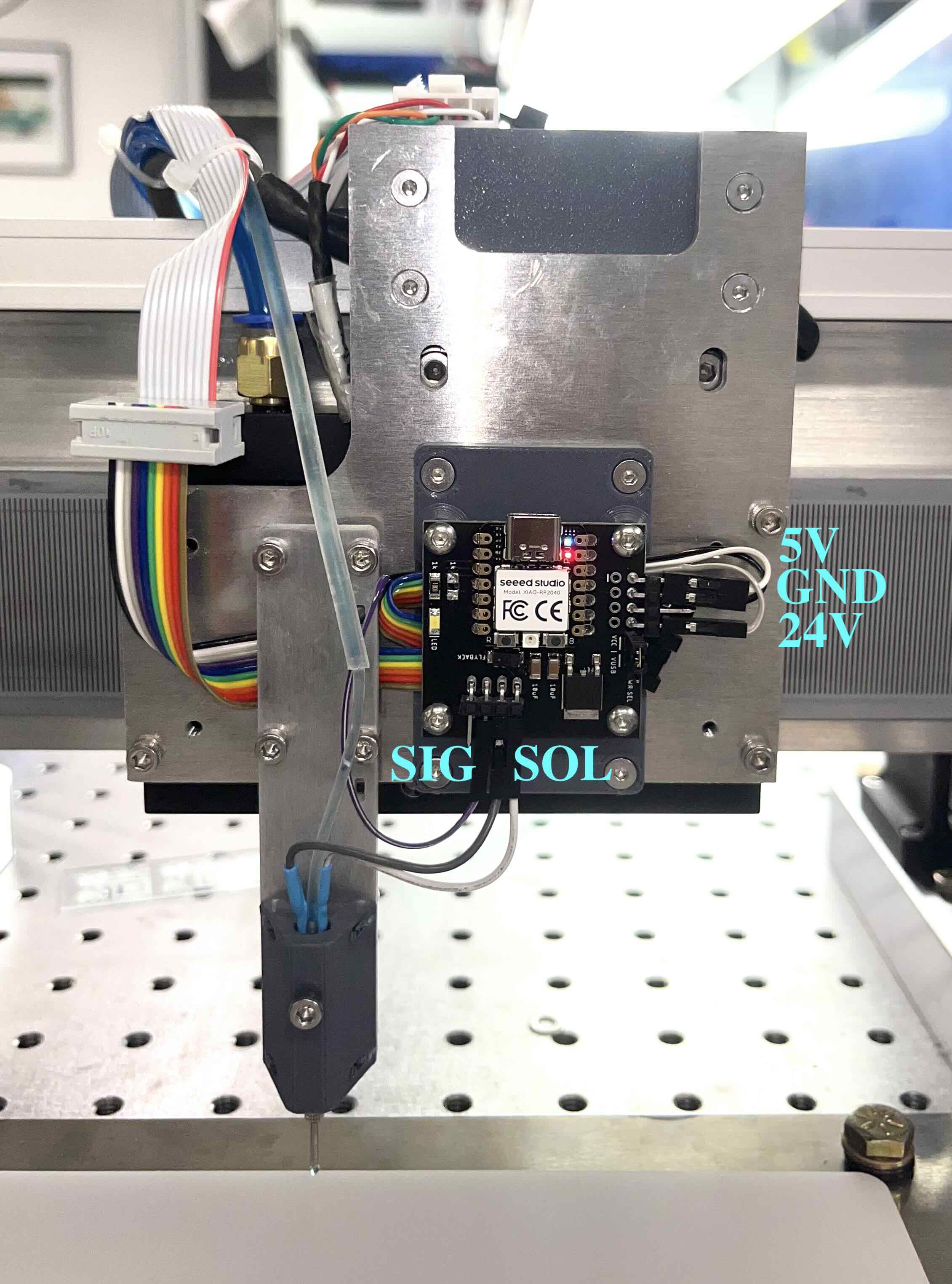
After wrapping up the syringe pump, I focused on the solenoid driver. The solenoid driver is used to control the solenoid
that is opens and closes the valve. This is somewhat of a departure from
the originally intended design of a piezo dispense capillary, but this was intentional as these
kinds of valves are an order of magnitude more affordable and substantially easier to control in an
array.
To get this to work, I needed to demonstrate that the valve can be opened with a 350µs pulse and
subsequently held open without burning the valve out. This is documented further in the solenoid driver page.
Getting the solenoid driver to work was a major win! And I was able to demonstrate the machine as
having been able to dispense droplets in a deterministic pattern.
Week 12: Droplets-on-the-fly
This week I focused on increasing dispense speed, notably getting the machine controller, Duet3D, to play nice with my external controller from Modular Things - thank you Jake and Quentin. The key here was to use the Duet3D in laser mode. This was a bit of a pain to get working, but I eventually got it there. The major roadblock was finding a PWM compatible pin that was also capable of being controlled by the M452 establishing command. For whatever reason, the actual laser/vfd pin Duet suggested using was totally non-functional. So I had to use other pins to debug. The pin I settled on was controlled by the opto couplers on the Duet3d 6xd mainboard as the optocooupler allowed me to use a pull-up on the "Therm" pin as built into the Low-MOSFET board. This convenient hack not only allowed me to control the solenoid driver safely, as there was no risk of providing higher voltages that could fry a microcontroller pin from the machine board, but also cut down on noise which was causing significant issues in interpreting PWM.
    ; Duet 3 MB6XD
    M452 C"io8.out" R255 F1000 ; Enable Laser mode, on io8, with max intensity being 255, and a PWM frequency of 1000hz
This command allowed me to dispense droplets on the fly instead of having to pause after each movement to
dispense, cutting down dispense time by 2 orders of magnitude for the system. To further reduce this
time, I began implementing raster clustering mode.
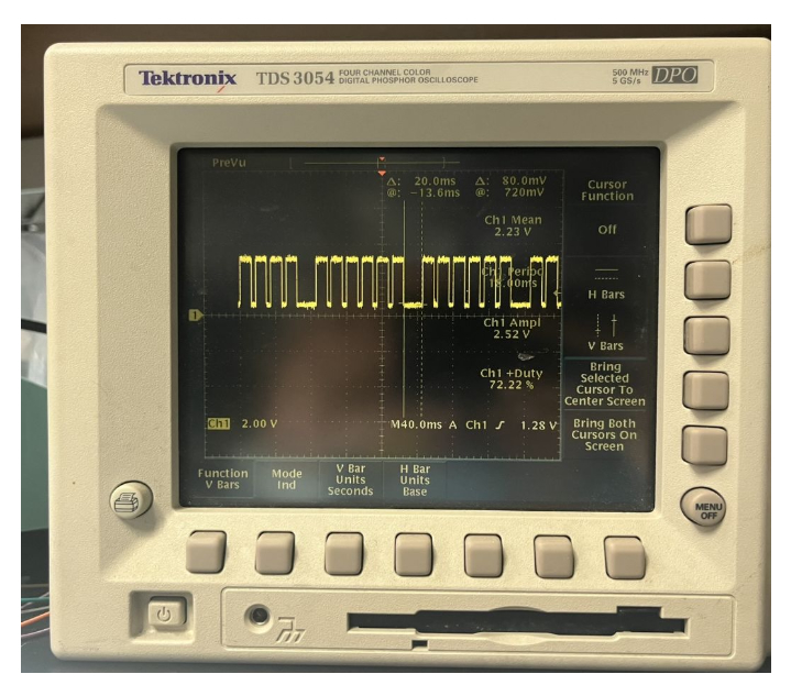
Pulsed signal with clustering
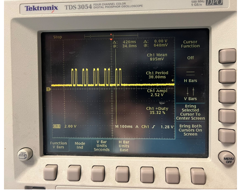
Pulsed signal with varied clustering
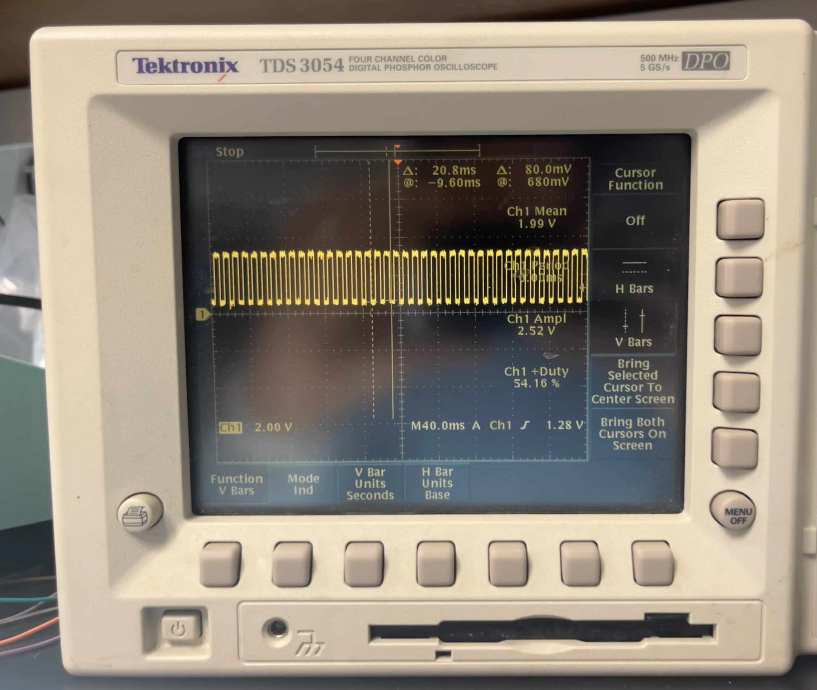
Pulsed signal corrected
This had some limitations, notably that the pause between pulses in a clustered command was
different than the pause between individual commands, creating periodicity in the dispense pattern.
To solve this, I included extra 0PWM pulses between the 255PWM pulses, I also found that just running
commands serially was fast enough for my purposes. Although, if I tried to loop commands, i.e. inside
of a "while True" the pulses were significantly slower by 10s of ms! Peculiar, but not a problem,
as it is trivial to generate G-code without loops or other cleverness in the age of 3D printing.
Putting all this together, I was able to generate this early dispense pattern. Droplet on the fly
dispense will be crucial to making a practical and useful machine. Unfortunately, during this
process the tip of the dispense head collided with the edge of the petri dish, despite not being secured
down, the petri dish somehow bound to the baseplate and caused the tip to snap off. Although I was able to glue
the tip back on, it continued to leak, causing the large droplets seen in the video.
Epilogue
This section serves as a reflection and overview of the entire project, discussing the successes, challenges, and future prospects of the molecular synthesizer machine. It encapsulates the journey from conception to realization and the lessons learned throughout the process.
Congratulations! The test is now over.