Component: Solenoid Driver
The purpose of this component is to drive solenoids safely and reduce power consumption.
There are two main characteristics a solenoid driver circuit requires beyond a typical switch. The
first is a flyback diode to protect the switching transistor and power supply from inductive spikes, and
the second is the ability to hold the solenoid open at a lower voltage. Most solenoids are rated for a
peak voltage, which is useful for actuating the solenoid. Once the armature has moved
within the coil, the solenoid needs far less force to maintain the armature in extension of the
spring.
Traditionally, this is accomplished by a somewhat complex circuit. To simplify things a bit, I'm
trying
a
PWM waveform to emulate a low average voltage by relying on the inductance of the solenoid itself.
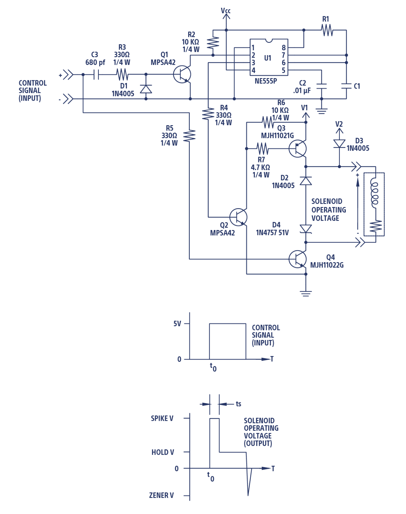
Image source: The Lee Co
To get started I used an early Modular Things MOSFET driver, based on a SAMD21 microcontroller.
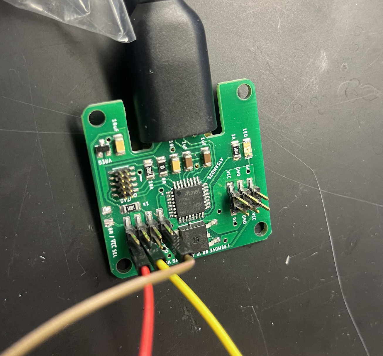
Although this worked effectively, it was a short term solution as their was no flyback driver across
output pins.
This meant that the MOSFET could be easily damaged by inductive spikes. Another issue I ran into was
that using the Arduino
IDE, whenever I stopped the code to debug, the current state of the pin was held. So if the solenoid
was
off, I would be fine,
BUT, and this is a HUGE "BUT" the solenoid would stay "on" if the previous state was "on". And this
meant a solenoid running
on 24V, could easily be burnt out off it wasn't rated for higher voltages. The test solenoid I used
was
rated to 12V, and my actual
valves were rated for 3V, so this would be a huge problem. In class, Jake suggested I switch to the
newer version of the board
based on the RP2040, which has a flyback diode across the output pins.
What's special about the RP2040? It can easily host a MicroPython interpreter, which has a built in
Try/Except feature. This means when I
provide a "Keyboard Interrupt"
from the IDE, in this case Thonny, the state of the pin is safely reset, and the solenoid is not
damaged. The following code is what
I used for the subsequent tests.
Micropython Code:
    from machine import Pin, PWM, Timer
    from time import sleep, sleep_us

    # constants
    spike_duration = 3.5 # spike duration, ms
    pulse_duration = 500 # dwell (including spike time), ms
    total_cycle = 3000  # period of the cycle, ms

    # establish pins
    led_pin = Pin(27, Pin.OUT)
    sol_pin = Pin(29, Pin.OUT)

    # establish timer object
    timer = Timer() # timer object

    # initiate variables
    duty = 0 # duty cycle, %
    duty_percent = 15
    hold_duty = round(duty_percent/100*65535) # reduced duty cycle, %

    # pwm object, off
    pwm_led = PWM(led_pin, freq=10000, duty_u16=duty)
    pwm_sol = PWM(sol_pin, freq=100000, duty_u16=duty)

    def pwm_control(timer):

        # on cycle
        pwm_led.duty_u16(65535) # set the duty cycle of the led
        pwm_sol.duty_u16(65535) # set the duty cycle of the solenoid
        sleep_us(int(spike_duration*1000))

        # pwm cycle
        pwm_led.duty_u16(hold_duty) # set the duty cycle of the led
        pwm_sol.duty_u16(hold_duty) # set the duty cycle of the solenoid
        sleep_us(int((pulse_duration-spike_duration)*1000))

        # off cycle
        pwm_led.duty_u16(0) # set the duty cycle of the led
        pwm_sol.duty_u16(0) # set the duty cycle of the solenoid

    print("initiate runtime")

    try:
        # timer initialize
        timer.init(period=total_cycle, mode=Timer.PERIODIC, callback=pwm_control)

        # allocate for extra application functionality
        while True:
            pass
            sleep(10)

    except KeyboardInterrupt:
        # catch a soft reboot or keyboard interrupt
        print("omg")


    # turn off the dang pins! this for your own good
    # (unless you want a burnt out solenoid)
    finally:
        print("purge")

        # turn off the main timer
        timer.deinit()

        # set pwm duty cycle to 0, this way needs a delay before
        # the pwm.deinit() call unfortunately
        #pwm_led.duty_u16(0) # set the duty cycle of the led
        #pwm_sol.duty_u16(0) # set the duty cycle of the solenoid
        #time.sleep(0.1)

        # turn off the pwm timers
        pwm_led.deinit()
        pwm_sol.deinit()


        # reinitialize pins as digital outputs
        led_pin.init(Pin.OUT)
        sol_pin.init(Pin.OUT)

        # set digital pins to 0
        led_pin.value(0)
        sol_pin.value(0)


        print("purge complete")
Component Demonstration
This approach appears to work initially, but the armature bounces after the initial spike and is insufficiently retained. The next step will be to try and get the solenoid to stay in place.
With a sufficiently high duty cycle, the armature is appropriately held in place at full extension.
For
an exposed solenoid like this, it's obvious to see this failure mode,
but it would be harder to parse as a failure mode in a closed design like a valve.
Additionally, there is a bit of buzz. I found that at frequencies in excess of 50kHz, the solenoid
is
held open quietly.
The goal here is to drive the solenoid at a low voltage and reduce the current draw of the circuit, to prevent the solenoid from overheating. I need to optimize such that the solenoid must be fully extended at the lowest duty cycle.
Current draw initially - peak current, ~1.42A:
Current draw following spike and hold - peak current, ~0.40A:
The next step will be to build a driver circuit that sits between the machine control system (Duet)
and the solenoid driver.
The solenoid driver will ultimately be for a small solenoid-controlled valve. Here is an example by
Festo that sits on the valve as a "backpack" and is controlled by an integrated driver that can send a
"spike and hold" waveform based on a standard step function input.