Model Free Control
If you’re going to use closed loop control, you are probably going to implement some flavor of model free control/heuristic control (probably PID). This flavor of controls doesn’t require you to have a model of your system, as the name would suggest, which is great— this means you don’t really need to know what’s up (and it is very hard to know what’s up) to get what you want.
Bang-Bang
Bang-bang control is a simple form of closed loop control, which alternates between two extremes to keep some measured value within a desired range.
There is a myriad of everyday appliances that works with bang-bang control. A simple example is thermostat systems in most Cambridge apartments, that measure the temperature and switch off when it runs above a maximum temperature and turns back on when it falls below a minimum temperature. The same goes for electrical water kettles that boil on full speed and just simply turn off when the water reaches its boiling point.
](imgs/Untitled.png)
Source: Introduction to embedded control
Bang-Bang control also has its own symbol:
 by Mik81](imgs/Untitled%201.png)
Source: Wikipedia by Mik81
PID
PID control is everyone’s favorite and is everywhere (insert existent citation).
Proportional 📎
Integral 🔨
Derivative 💦
Here it is in block diagram form:
The way this works is that you have a desired set point (in the diagram, r(t)), and your measured/actual variable (y(t)). You calculate the error (e(t)), which then gets fed into the PID controller.
The proportional controller multiplies the error by the proportional gain Kp.
The derivative controller multiples the rate of change of the error by the gain Kd.
The integral controller multiplies the integral of the error by the gain Ki.
These are then summed together and the output value is inputed to the plant.
](imgs/PID_en.svg)
Source: Wikimedia Commons https://upload.wikimedia.org/wikipedia/commons/4/43/PID_en.svg
You will also very commonly see variants of PID controllers, aka the P, PI, or PD controller (it’s probably more common to see not-full PID controllers).
When thinking about PID controllers, I think it’s helpful to revisit the fundamental truth, once more, that everything is a mass-spring-damper system: if our set point is x0, and our measured position is x, then the P controller is pushing according to Kp * (x0-x) or perhaps rather: -Kp * (x0-x)
What does this look like? a spring 😛
Similarly, if set point x0 stays constant, then Kd * ( Δ e(t) / Δ t) = Kd ((x_0-x(t))-(x_0 - x(t-1)))/Δ t = Kd ( Δ x / Δ t )
I.E. a damper 😎
And I am terribly sorry if the typing is bad it is so hard to type the math tex.
.](imgs/Untitled.gif)
Spring-mass system under-damped Source: Wikipedia https://en.m.wikipedia.org/wiki/File:Spring-mass_under-damped.gif.
Then the Integral term — here the analogy falls apart a bit. It’s just an extra forcing system in play. (And note that it’s generally implemented in a “leaky manner”, e.g. the maximum integral error is capped, the integral term only kicks in within some range of the set point, etc.)
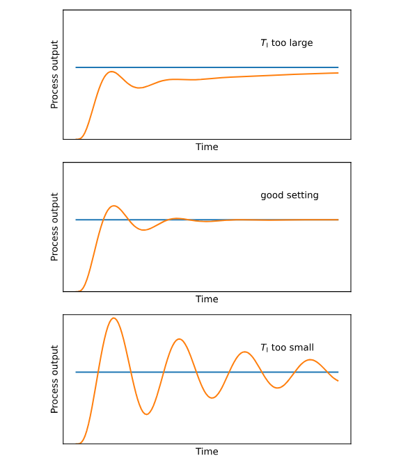
)](imgs/Untitled%203.png)
Proportional (Integral) (Derivative) contrl (source: SM LEASE)
](imgs/PID_Compensation_Animated.gif)
Source: Wikipedia.org https://en.wikipedia.org/wiki/Proportional–integral–derivative_controller#/media/File:PID_Compensation_Animated.gif
So with that in mind, let’s look at how changing the Kp, Kd, and Ki gains impact our system’s ability to reach a set point. In general, when you’re tuning PID gains (manually or via some method), you will start with just the Proportional term and the other set to zero.
Kp will drive you near your set point, like a spring will— if it’s too stiff you will introduce oscillations, if it’s not stiff enough, you will not reach your set point. A large Kp makes your system responsive! Too large and it becomes unstable.
From there, depending on what you’re up to, you will introduce either the derivative or integral terms.
Kd will help damp out oscillations in your system (minimizing overshoot) and improve your stability. However, if you make Kd too large, your system’s stability is going to go off a cliff (typically a fairly loud cliff). This is very easy to do, esp for discrete time systems (i.e. the systems you will be working with).
Now that you’ve got these two gains going, you may notice that you have some steady state error (you’re stabilizing around a point that’s not actually your set point). To address this, we add in the Ki gain, which acts of the sum/integral of your error. (Your small steady state error, which is too small for your P gain to address, now becomes large over multiple time steps). As previously stated, you will likely do some flavor of messing with your integral term, otherwise it’ll do unpleasant things to your system.
See next:
- PID tuning methods (e.g. Ziegler-Nichols… perhaps the most popular of the real methods, and likely appropro for systems relevant to this class): https://en.wikipedia.org/wiki/Ziegler–Nichols_method
- My favorite method is manual tuning! no measurement! only guessing!
- Cascade PID (PID into PID … into PID?): https://www.mathworks.com/help/control/ug/designing-cascade-control-system-with-pi-controllers.html;jsessionid=d2b6d7f55f582342f16b86beee3a
My recommendation:
At a practical level, for this class, this overview for PID for Arduino is very clear and addresses most of the problems you will run into during implementation: http://brettbeauregard.com/blog/2011/04/improving-the-beginners-pid-introduction/