I prefer MicroPython to Arduino
Week 10
Output devices
Software Tools: Autodesk Fusion 360 (aka Autodesk Eagle), Universal Gcode Platform (Version 2.0.20) to send the gcode file to the milling machine, Quentin's online gerber to image tool, and Professor Neil's modsproject online tool to create a gcode file.
Hardware Tools: Genmitsu milling machine
Previous experience: Board design experience from week 06
This week can be broken down into three phases:
- Designing a board with an output to a speaker
- Milling the board and soldering the components on
- Making the speaker do something
Video of a bad version of the Mario Bros theme song playing on the speaker.
Helpful links for future reference:
- How to send analog audio from RP2040 to speaker
- Step by step guide on connecting speaker and amplifier to Pico
- Guide to play sound from an SD card with the Pico and micropython
Designing the board
Similar to the input devices week, I needed some help this week. I referenced
Matt Keeter's final project
from 2019 for inspiration. I decided I want to setup a simple speaker from Amazon
and a LM4871M amplifier. I also set out to
include a micro SD card and a push/pull reader, but I could not find the right parts in our inventory. I will continue with the board next week
and include the micro SD card.
For the speaker setup, I read the data sheet for the LM4871M amplifer and copied the typical circuit they provided. See the data sheet link below for reference.
After a few hours in Autodesk Fusion 360 on a plane ride, I had a spacious board design for the RP2040 microcontroller, amplifier, speaker connection, and
SD card push/pull slot.
I followed the process I documented in Week 06 Electronics Production
to create the necessary IMG files and gcode files from the gerber files that I exported from Autodesk Fusion 360.
Here are the files I created for easy reference:
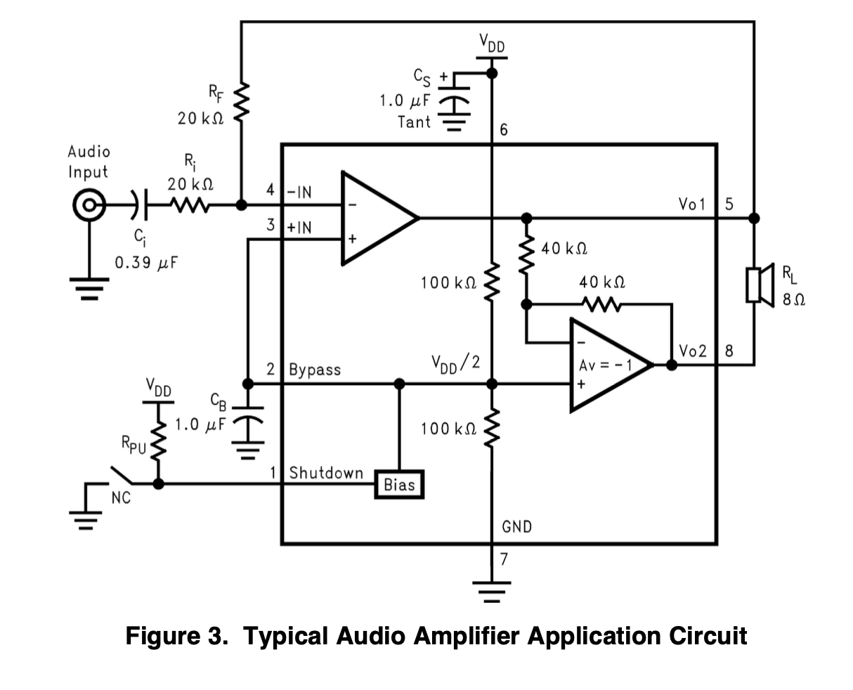
Screenshot of the LM4871 amplifier data sheet
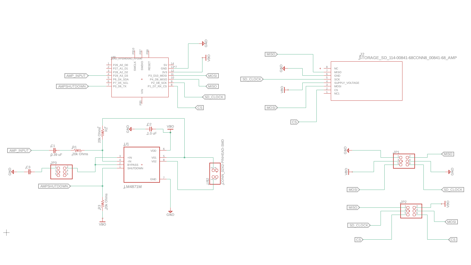
Screenshot of the board schematic
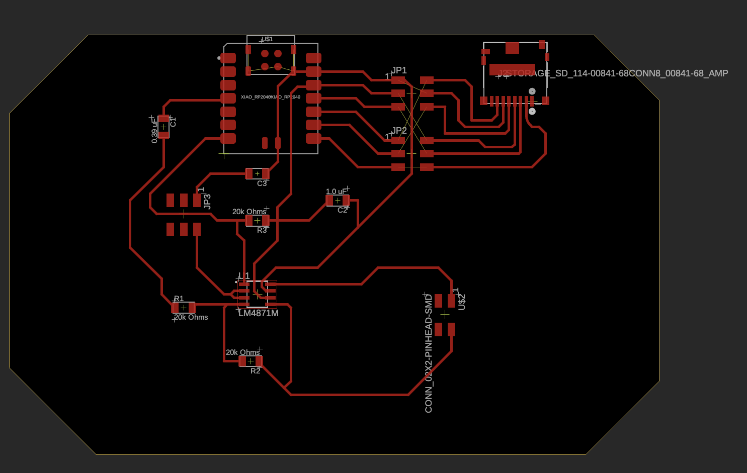
Screenshot of the PCB
Milling the board
I used the Genmitsu milling machine in E15-043 with the Universal Gcode Sender software on the adjacent desktop machine.
I followed the process I documented in Week 06 Electronics Production to
mill the board. The only difference this week is that I used double-sided tape to secure a new board on the sacrificial board.
I felt comfortable using the machine, zeroing the z-axis, and finishing the board. There were no issues.
If needed, this website has a good guide on how to use the "UGS platform".
These are the steps I followed to run the milling machine:
- Click “Open” - select my gcode file (.nc)
- Check if the drill is the right one (1/64” for traces, 1/32” for edge cutting)
- Click “macro” -> “[1] Raise Z”
- Setup the grounding cables, and click “macro” -> “[2] Probe and zero Z”
- Position the drill to the right position and set X0 and Y0
- Press the play button that reads “send” and start milling
- Turn on the vacuum cleaner and wear ear mufflers or noise-cancelling headphones
- Repeat the steps above for the edge of the board
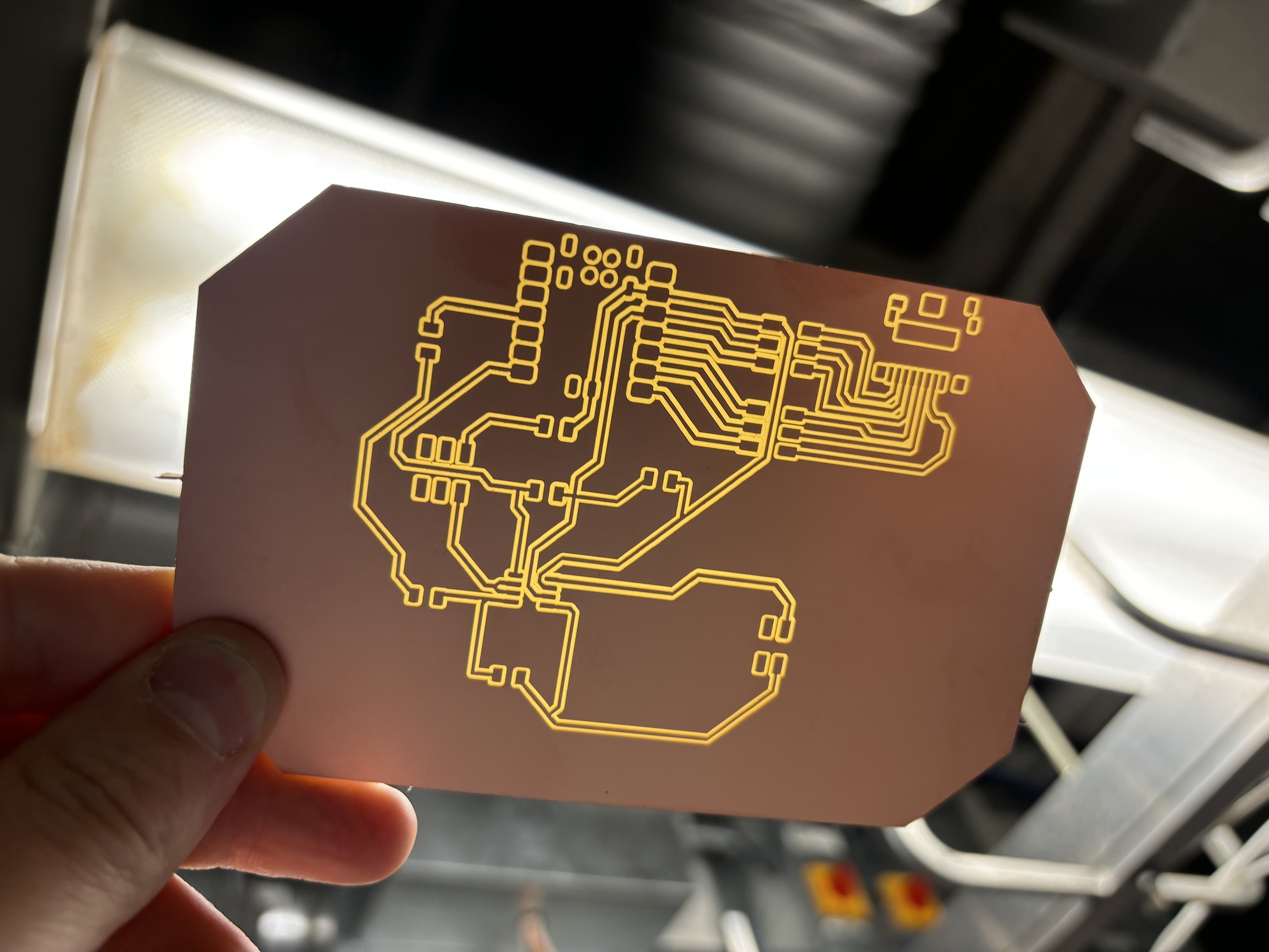
Final empty board ready for soldering
Soldering components to the board
This was easier than the tiny microphone I soldered onto the board last week. I used the components on the schematic, with an important disclaimer. Since we do not have 20k Ohm resistors in the lab, I used 10k Ohm resistors instead. Additionally, we do not have 0.39 uF capacitors, and I instead used a 1.0 uF capacitor.
I used the following components for my board:
- RP2040 microncontroller
- LM4871M amplifierlink to DigiKey
- Three 1.0 uF capacitors
- Three 10k Ohm resistor
- One 2x3 header
- One 2x2 header
- One short piece of cable
- One simple 4 ohm, 3 watt speaker from Amazon
I then patiently and deliberately soldered the components to the board with the help of flux. This week I used a different soldering iron at 320 C which seemed to work MUCH better than the iron I used last week.
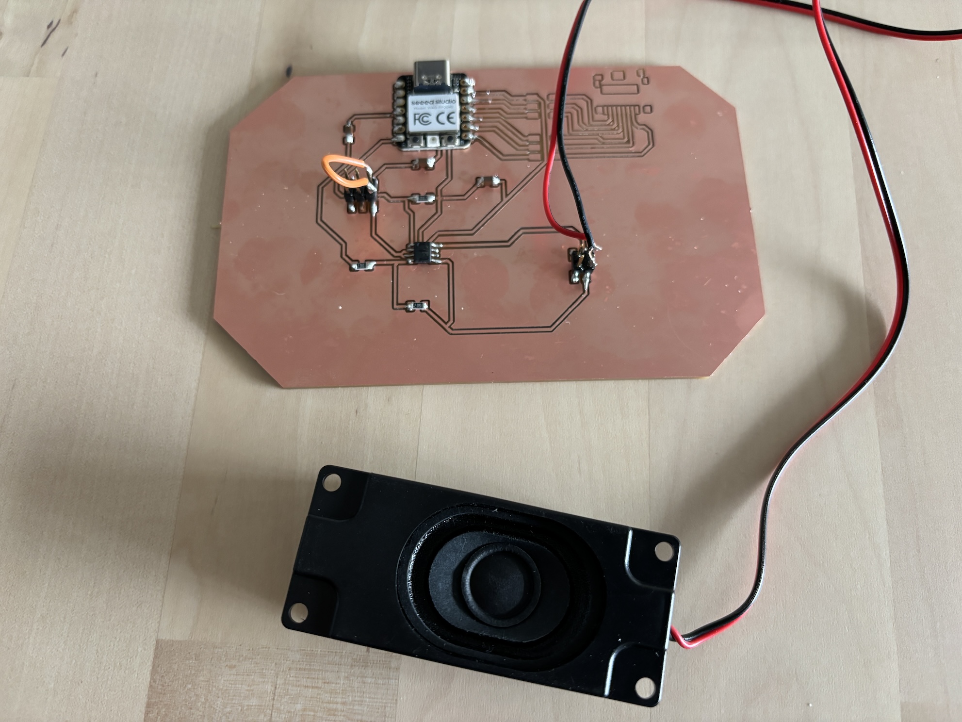
Final soldered board
Sending sound to the speaker!
As noted above, I didn't have the components needed to install a micro SD card slot, so I just focused on using the speaker as an output device. I used Pulse Width Modulation (PWM) to create different frequency sounds with the speaker. In the context of speakers, PWM is used to regulate the power that drives the speaker's cone, producing sound waves.
First I setup Thonny with the Xiao RP2040 microcontroller. I followed the process I documented in Week 03 Embedded Programming so I could write and upload a program to the RP2040 board. Specifically, I did the following:
- Plug in RP2040 to laptop via USB-C cable
- All the LEDs turn on, including the large one at the base of the device which blinks and changes colors
- I pressed and held the “B” button, then pressed and released the “R” button. This turned off the light, and then the RP2040 appeared as an external drive with the name “RPI-RP2”
- I installed the .uf2 file on the microcontroller by clicking and dragging the file to the "RPI-RP2" drive
- In Thonny, I went to the Run menu to select the option "Configure interpreter..."
- I made sure that MicroPython (RP2040) was selected, and the right port was selected (see screenshot)
- I Googled the frequency pattern of the Mario theme song. Lucas, my nephew, loves Mario and ultimately this speaker setup will be in my final project. The Microcontroller is using GPIO29 to send output signals to the amplifier, therefore I used pin 29 in the code.
- I uploaded the simple code to the Xiao microcontroller as "main.py" so it runs each time the microcontroller is connected to power. See the video to the right.
Here is the simple micropython program I wrote and uploaded to the board:
import machine
import utime

machine.PWM(machine.Pin(0)).freq(500)

def play_frequency(pin, frequency, duration):
	if frequency == 0:
		utime.sleep(duration)
	else:
		pwm = machine.PWM(machine.Pin(pin))
		pwm.freq(frequency)
		pwm.duty_u16(512)  # 50% duty cycle
		utime.sleep(duration)
		pwm.deinit()

def play_mario_theme():
	melody = [
		(659, 250), (0, 50), (659, 250), (0, 50), (659, 250), (0, 50), (523, 250), (659, 250),
		(0, 50), (784, 250), (0, 50), (392, 250), (0, 50), (523, 250), (0, 50), (392, 250), (0, 50),
		(330, 250), (0, 50), (440, 250), (0, 50), (494, 250), (0, 50), (466, 250), (0, 50), (440, 250),
		(0, 50), (392, 250), (0, 50), (659, 250), (0, 50), (784, 250), (0, 50), (880, 250), (0, 50),
		(698, 250), (0, 50), (784, 250), (0, 50), (659, 250), (0, 50), (523, 250), (0, 50), (587, 250),
		(0, 50), (494, 250), (0, 50), (523, 250), (0, 50), (440, 250), (0, 50), (392, 250), (0, 50),
		(784, 250), (0, 50), (880, 250), (0, 50), (698, 250), (0, 50), (784, 250), (0, 50), (659, 250),
		(0, 50), (523, 250), (0, 50), (587, 250), (0, 50), (494, 250), (0, 50), (523, 250), (0, 50),
		(440, 250), (0, 50), (392, 250), (0, 50), (659, 250), (0, 50), (784, 250), (0, 50), (880, 250),
		(0, 50), (698, 250), (0, 50), (784, 250), (0, 50), (659, 250), (0, 50), (523, 250), (0, 50),
		(587, 250), (0, 50), (494, 250), (0, 50), (523, 250), (0, 50), (440, 250), (0, 50), (392, 250),
		(0, 50), (0, 250),  # Pause
		(784, 250), (0, 50), (0, 250),  # Pause
		(659, 250), (0, 50), (0, 250),  # Pause
		(523, 250), (0, 50), (0, 250),  # Pause
		(587, 250), (0, 50), (0, 250),  # Pause
		(494, 250), (0, 50), (0, 250),  # Pause
		(523, 250), (0, 50), (0, 250),  # Pause
		(440, 250), (0, 50), (0, 250),  # Pause
		(392, 250), (0, 50), (0, 250),  # Pause
	]

	for note in melody:
		play_frequency(29, note[0], note[1] / 1000)  # Convert duration to seconds

if __name__ == "__main__":
	play_mario_theme()
Video of the Mario theme playing when the RP2040 is connected to power
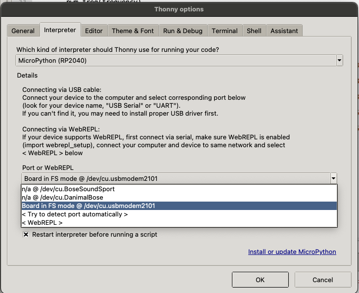
Screenshot of setting up Thonny