Summary
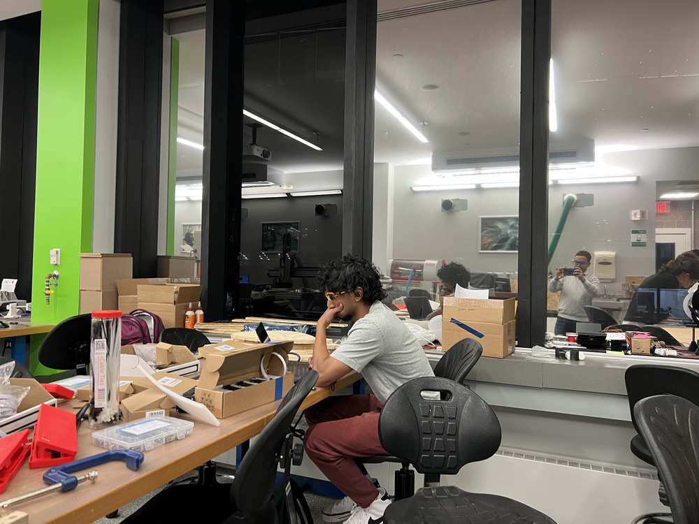
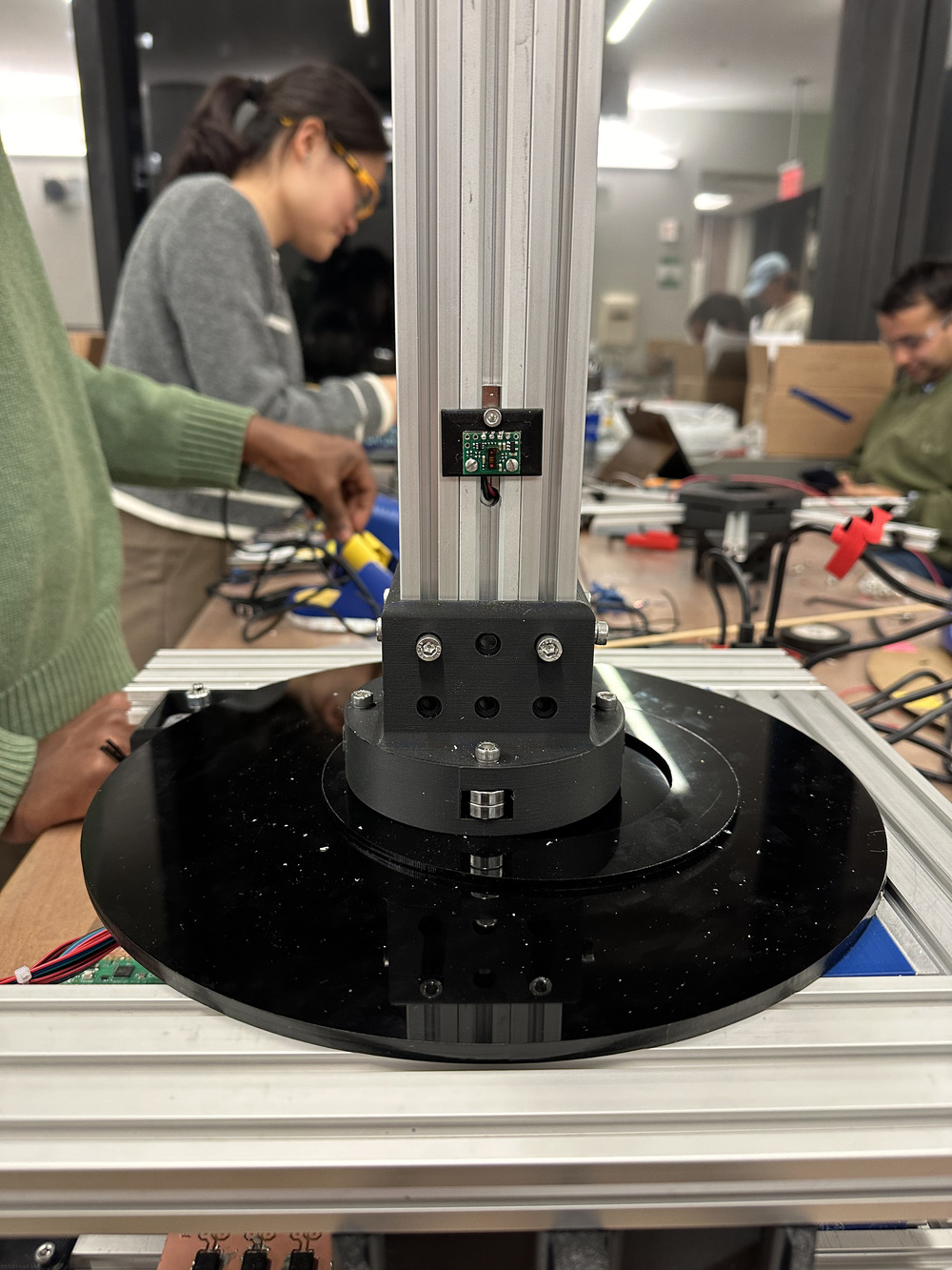
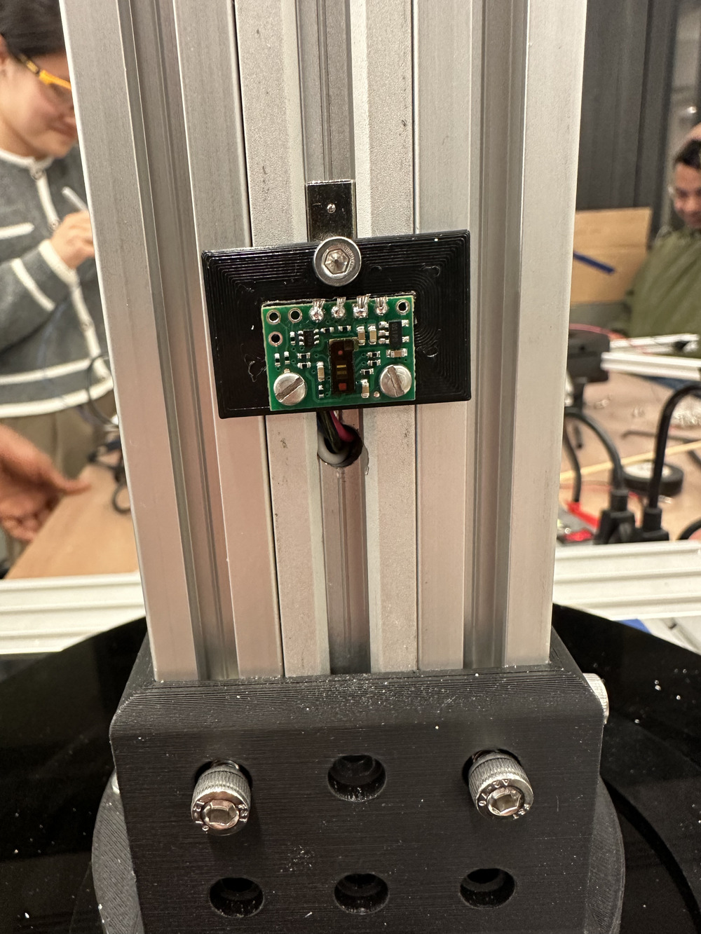
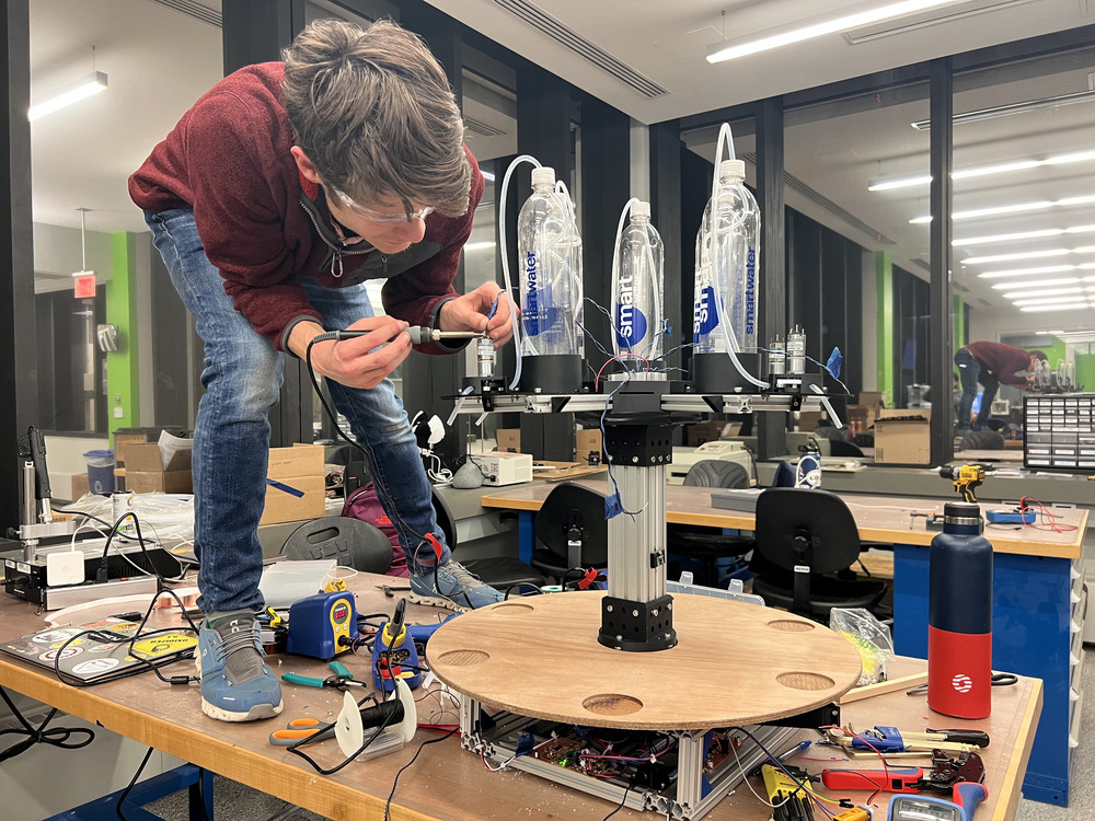
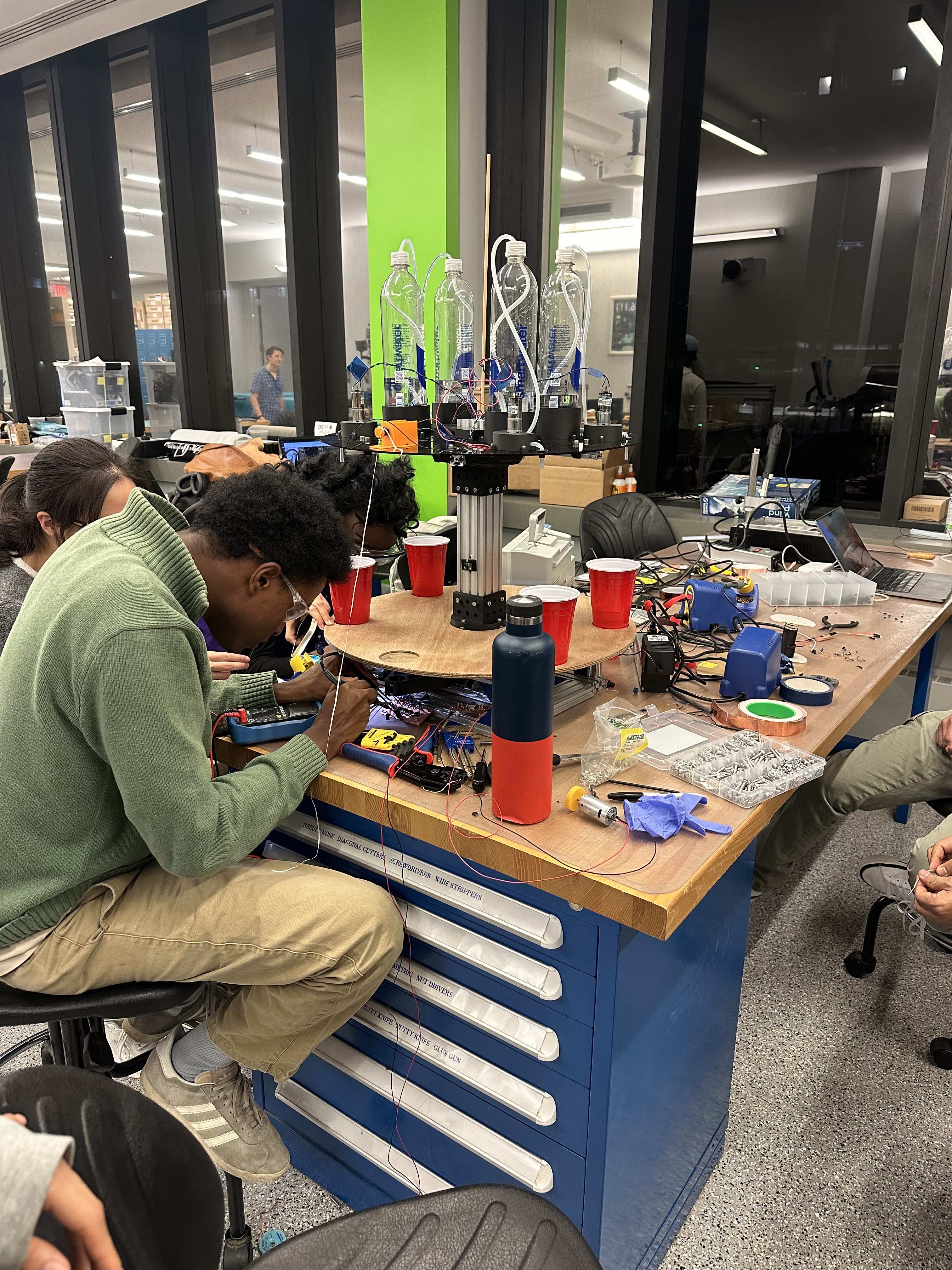
No project is ever finished, but we are thrilled to have the machine functional. It is able to spin the table to position the cups under the pumps, and liquid can be dispensed. We even got the neopixel lights working to light it up like Neotokyo. We ran out of time to implement the cup detection module and hall effect sensor to home the table during start up. We all learned a hard lesson about supply side time management, as Neil would put it. It was difficult to coordinate differnt sub-projects until we had a mostly built unit on Tuesday night. We all want to see this project working regaurdless of what we turn in on Wednesday. Many of us agreed to continue working on the Barduino to get it to its fullest potential. We will update the documentation when we get the rest of the machine working!
Class demo
Test in the lab
Highlight of the week is how we as a team come together and pull out what though to be impossible. Team meeting with the experts in the field made it easiear.
Overview:
Turn table with drink pouring and mixing technology. Place the cup in the machine. Select drink on UI. The turntable rotates the drink through multiple stations which add ingredients and mix the drink, then returns it to the user.
Team
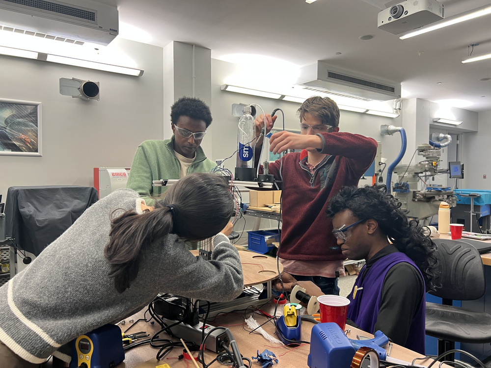
We are working as one group on all parts of building the machine. Each sub-team is focused on specific components to make everything work together.
| Subteam | Members |
|---|---|
| Pump/Dispenser | Lily, Robin, Nathaniel |
| Stirring Mechanism | Emma, Alex, Sungmoon, Sophia |
| Turn Table/Main Board | Fan, JD, Hayashi, Laxman |
| UI Control System | Jocelyn, Kathy, Alicia, Michael |
| Cup Detection | Addison, Liam, Vivek |
| Documentation | Laxman, Alicia |
Brainstorming Sessions
After class on Wednesday, we brainstormed several ideas for machine-building projects. Two ideas stood out during our discussion. The first idea, proposed by Addison, was a pick-and-place machine for Minecraft blocks. The second idea, suggested by JD, was a Shot Bot that uses peristaltic pumps to fill shot glasses with random liquids. Below are the details of these ideas and our decision-making process.
Pick and Place Machine for Minecraft Blocks
Addison's idea involves using a modded Minecraft world as the control interface for a physical pick-and-place machine. When blocks are placed or destroyed in the game, the machine physically picks them up and drops them at the specified location. The concept requires several components:
The pick-and-place frame is the physical structure with motors that move along three axes to handle block movement. A claw device, potentially using a toggle magnet, would be responsible for picking up and moving blocks. Onboard electronics would control the frame and claw device, while a custom Minecraft mod would detect in-game block changes and send this information to a local web server. The web server, in turn, would send placement data to the onboard electronics. A control loop mechanism would ensure accurate movements of the tool, and blocks would need to be fabricated to fit this system.
Shot Bot
JD's Shot Bot is designed to use two peristaltic pumps to draw liquids from separate containers and fill shot glasses with random liquids, such as water or vinegar. The system includes a turntable driven by a stepper motor and a distance sensor that detects whether the filling station is empty, has an empty glass, or contains a full glass. The machine would operate in two phases: loading and filling.
During the loading phase, the machine starts empty. A glass is placed into the machine, and the sensor detects its presence. The turntable then rotates to the next available position. This process repeats until the desired number of glasses are loaded or the machine is full. Once loading is complete, pressing the "fill" button exits the loading phase, and the glasses are filled with liquid.
Other Ideas and Final Decision
We also considered other creative ideas, including a bamboo production line, a clothes-folding machine, a building assembler, and a writing machine. After evaluating the feasibility and excitement of each idea, we decided to move forward with the Shot Bot. We have named the project "Barduino."
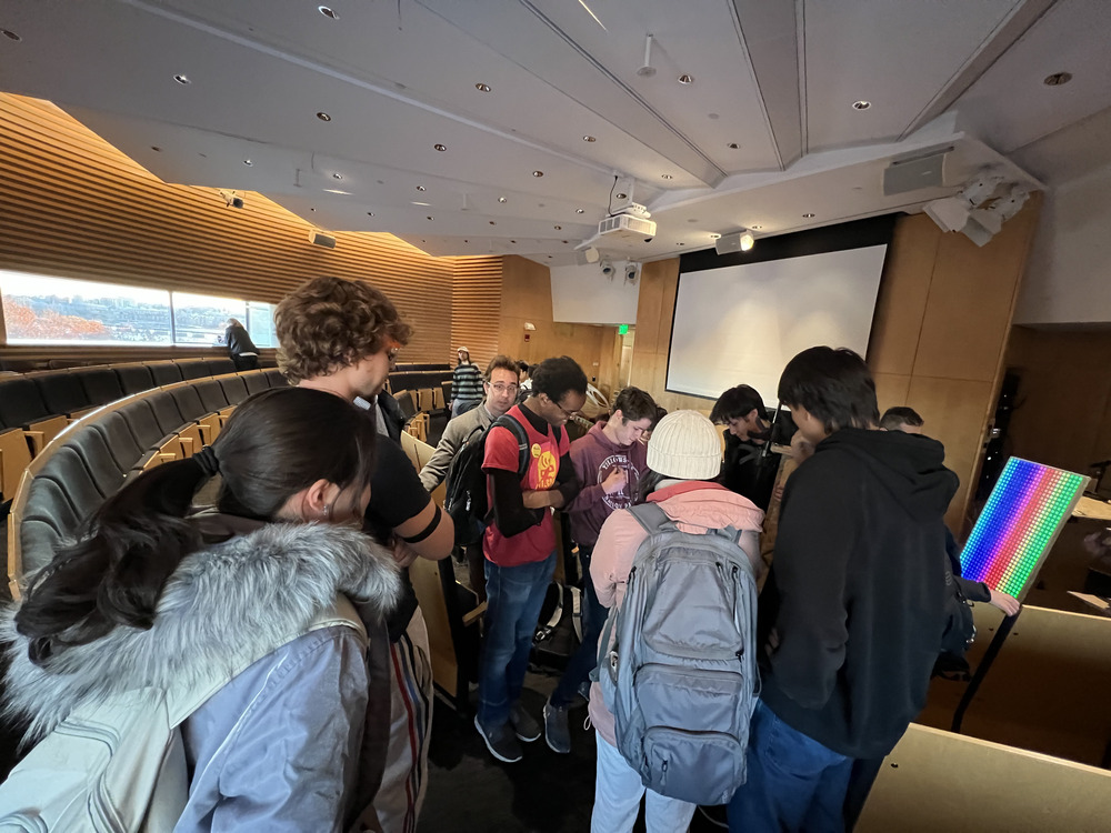
We will meet again on Thursday before the recitation, from 3-5 pm, to discuss ideas and plan our approach for machine week.
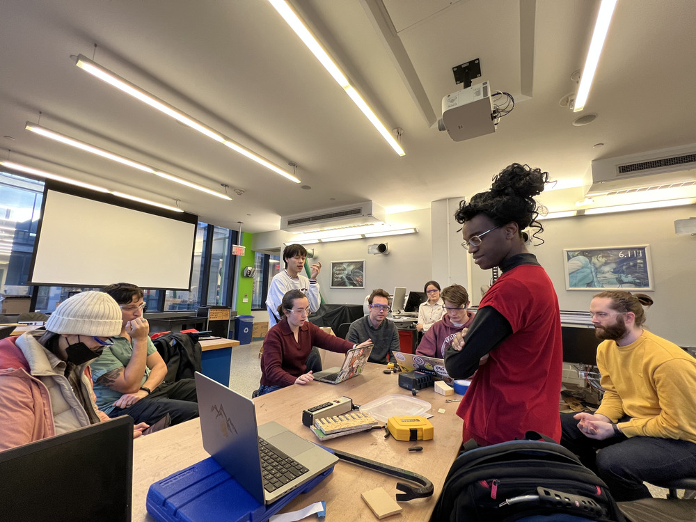
Jake came to help us on Saturday and Monday and checked some of our idea and gave us excellent advices. Big thanks to him.
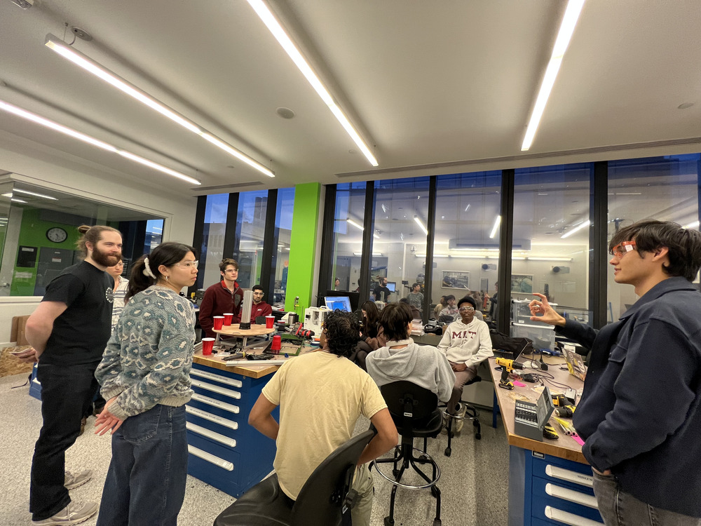
General
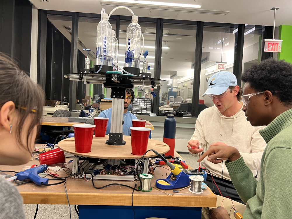
This section documents the things that we all the sub-teams worked together.
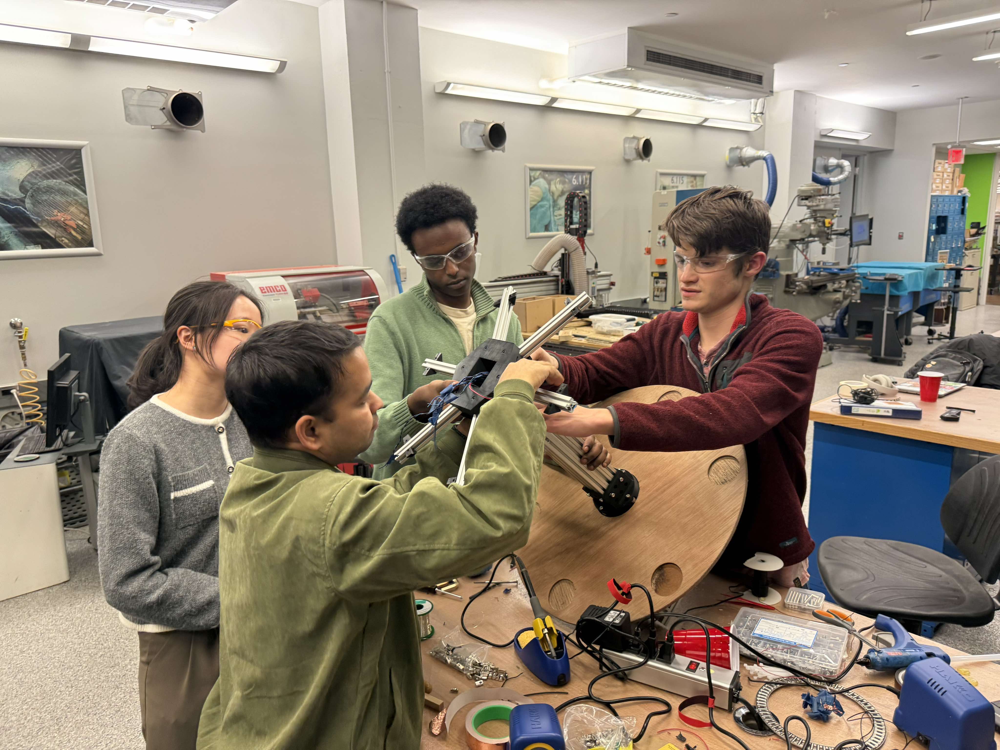
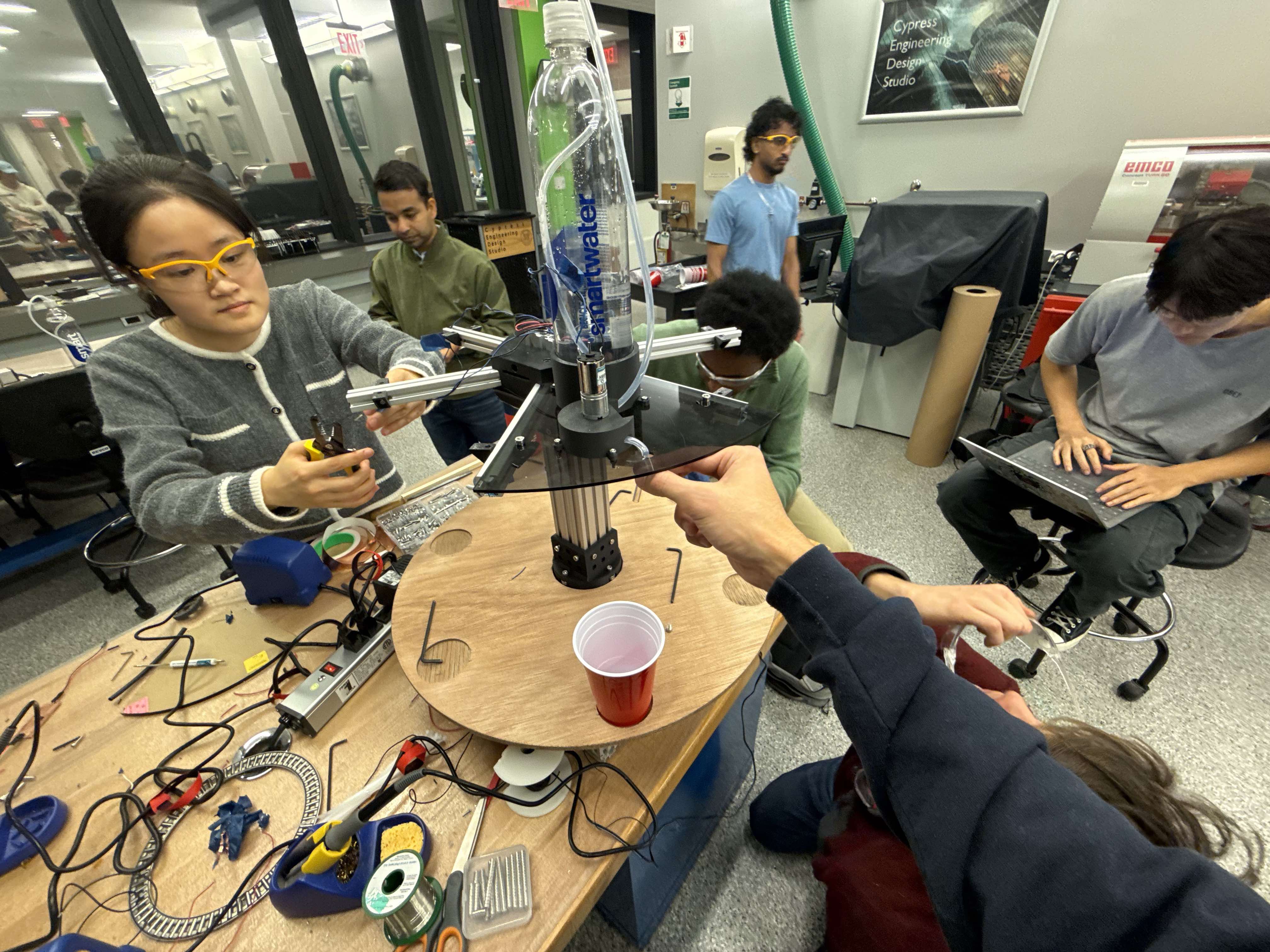
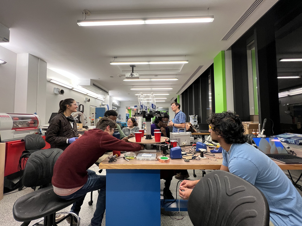
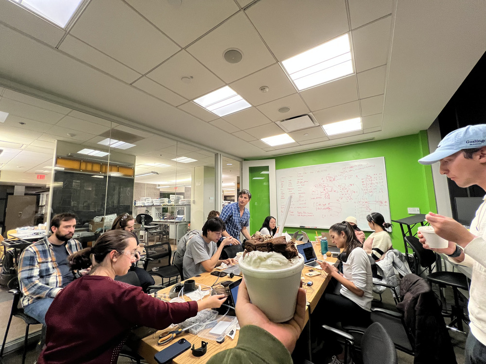
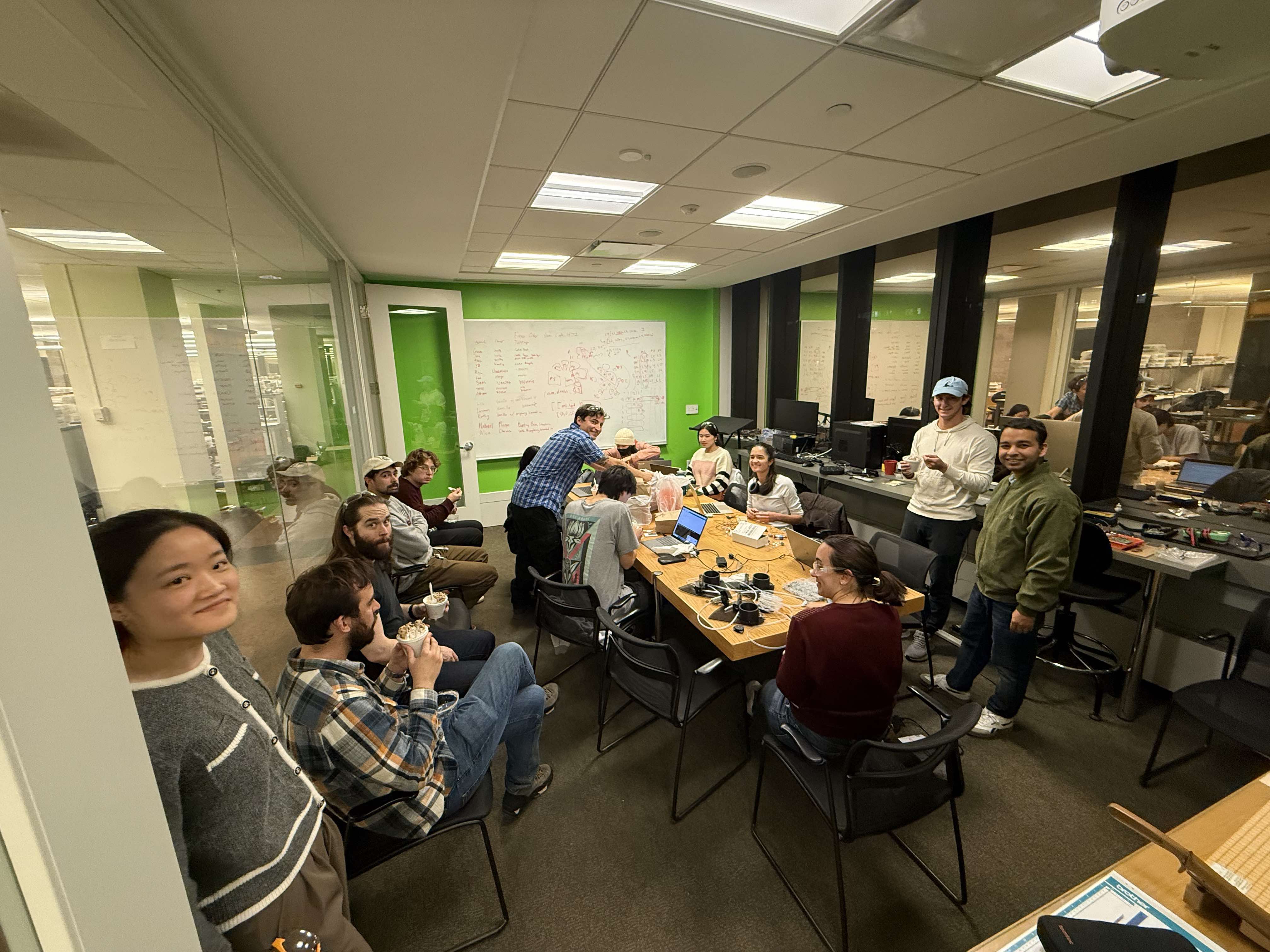
Pump and Dispenser
This section is for documenting work related to pump and dispenser.
We decided to make our own peristaltic pumps for this week because as neil said it's not that hard. A peristaltic pump works by basically pushing on a tube and then the liquid follows the pressure and goes through. We did some research on different peristaltic pumps and created the cad for an initial one. Here's the rotor part spinning.
When put entirely together, it didn't work because it wasn't pressing tight enough on the tubing to create a full seal. This video is kinda misleading cause its not actually moving anything
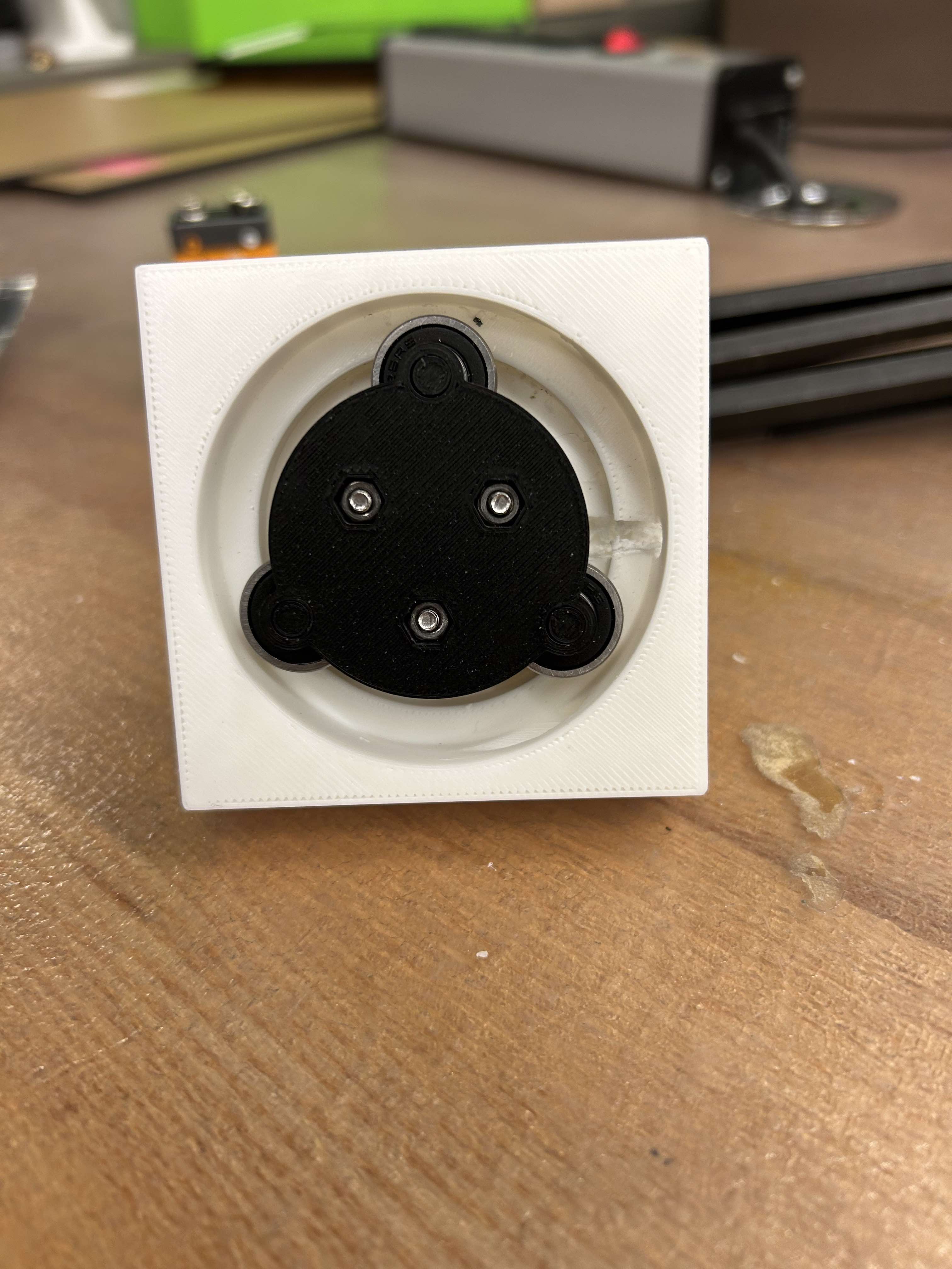
we resized it a bit and got it working! That said, this designed ended up being kinda finnicky. We printed some using a different 3D printer and then it wasn't working anymore so we added a couple layers of eletrical tape to make the wall thicker and that did the trick
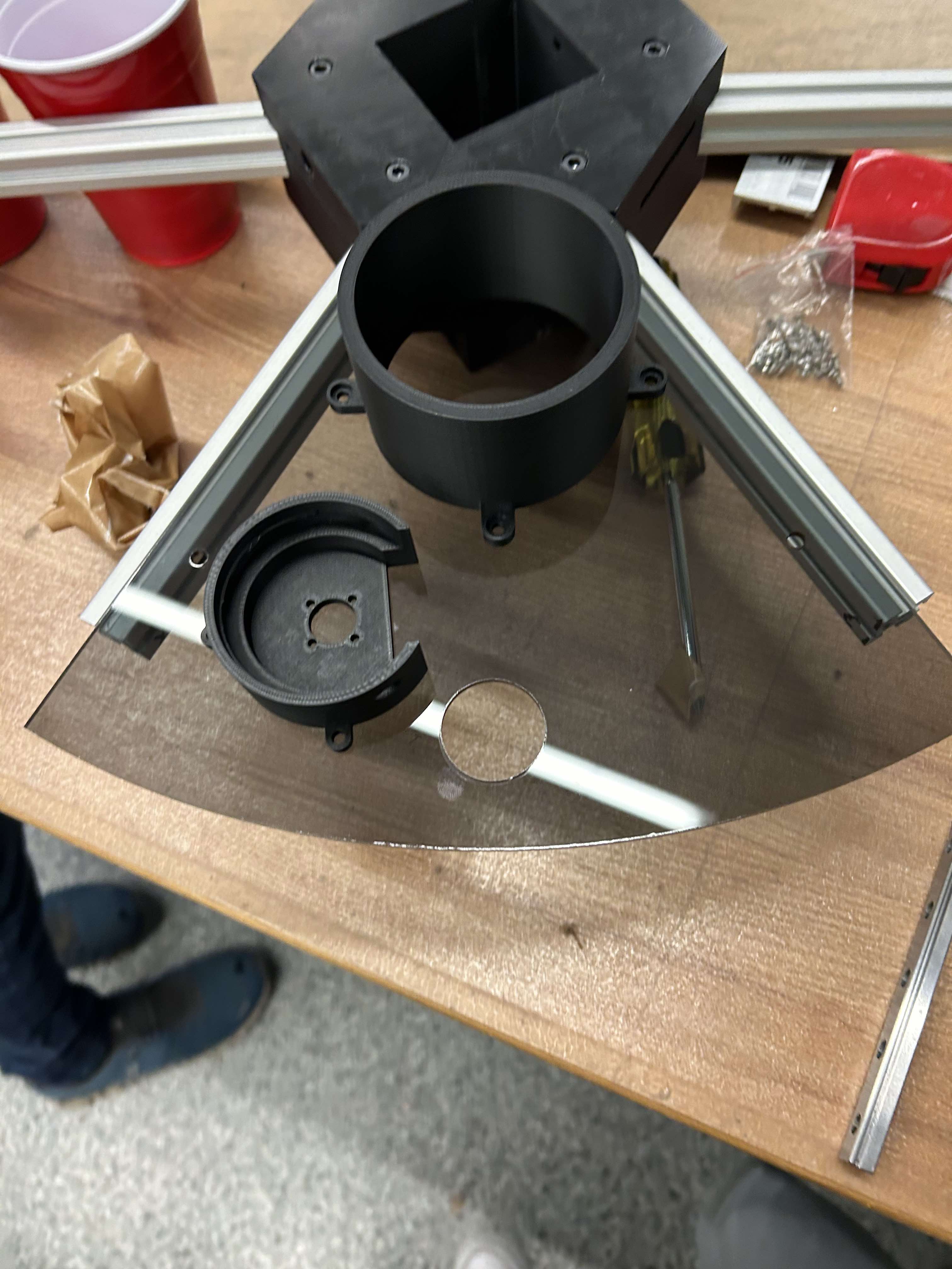
As a group we decided on using acrylic panels for the top surface so we also caded some mounting holes and bottle holders to complete the pump dispenser modules
Stirring Mechanism
This section is for documenting work related to stirring mechanism
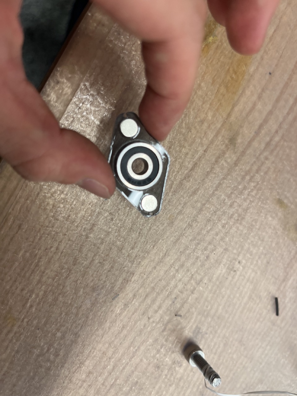
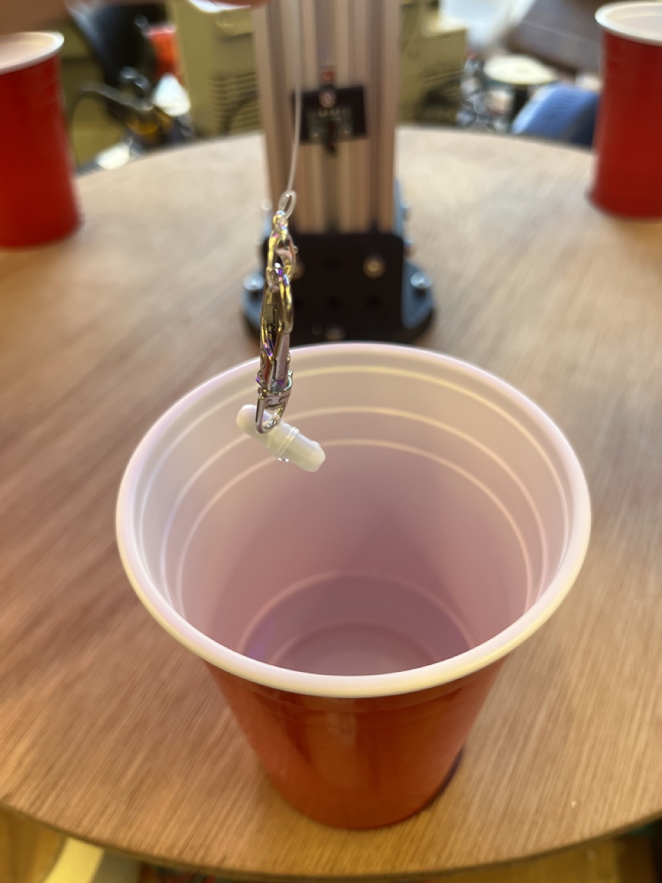
Turn Table
The Turn Table team focused primarily on hardware-related tasks. This included designing the bearing system, cutting, and assembling aluminum extrusions. This section documents the efforts and execution of the Turn Table team to achieve a functional rotating table.
We started with the concept design, which included a 24-inch turn table supported by a strong vertical column. This column would hold the drinks and pumps at the top and feature gears at the bottom. The vertical column was made from aluminum extrusion, as it was the provided material and is extremely easy to work with.
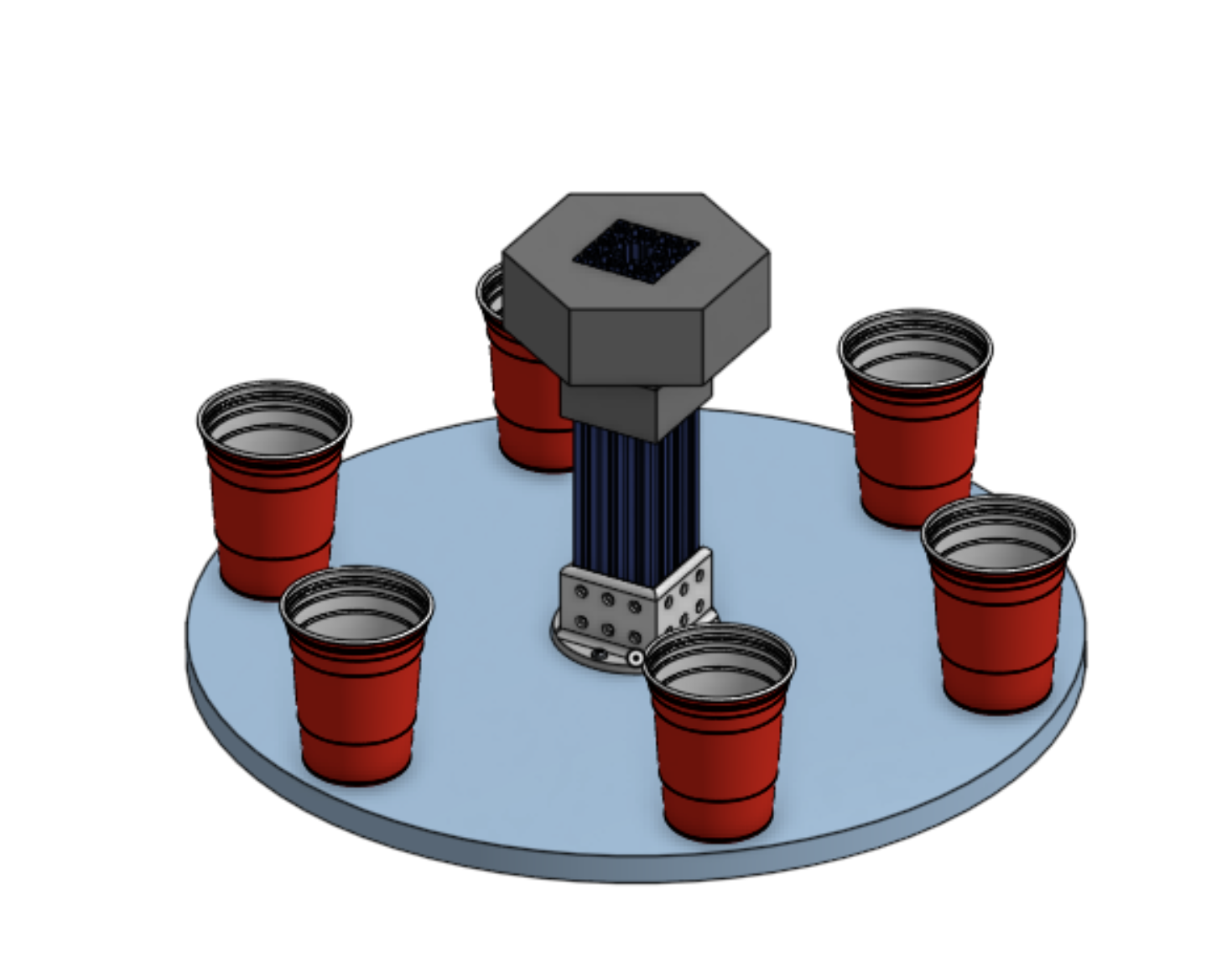
Simultaneously, we designed the gear system. Our gear system has a 6:1 ratio, meaning one full rotation of the stepper motor rotates the table by 60 degrees. This was ideal, as each cup needs to rotate 60 degrees to reach the next drink dispensing station. Below is a Fusion 360 animation showcasing how the gear system works.
The dimensions of the gears that create the 6:1 ratio are as follows:
Dimensions of the large gear:
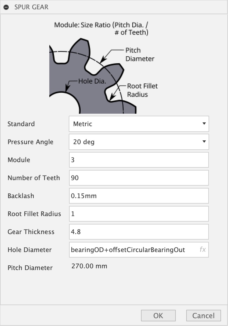
Dimensions of the small gear:
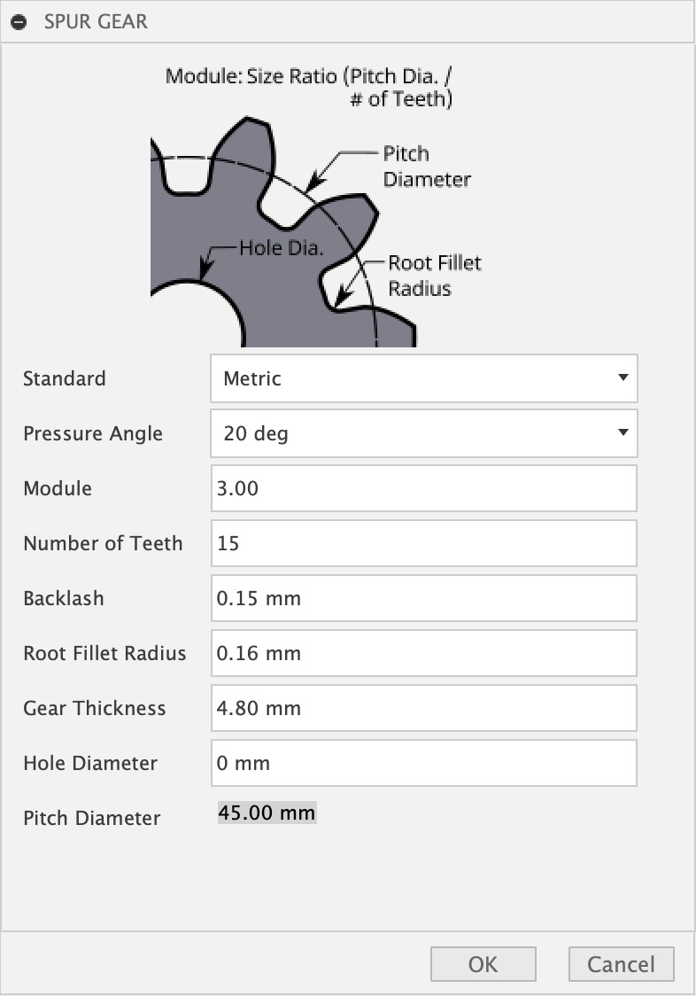
After designing the gear system, we used a laser cutter to cut acrylic for the components. Below are the settings we used for cutting:
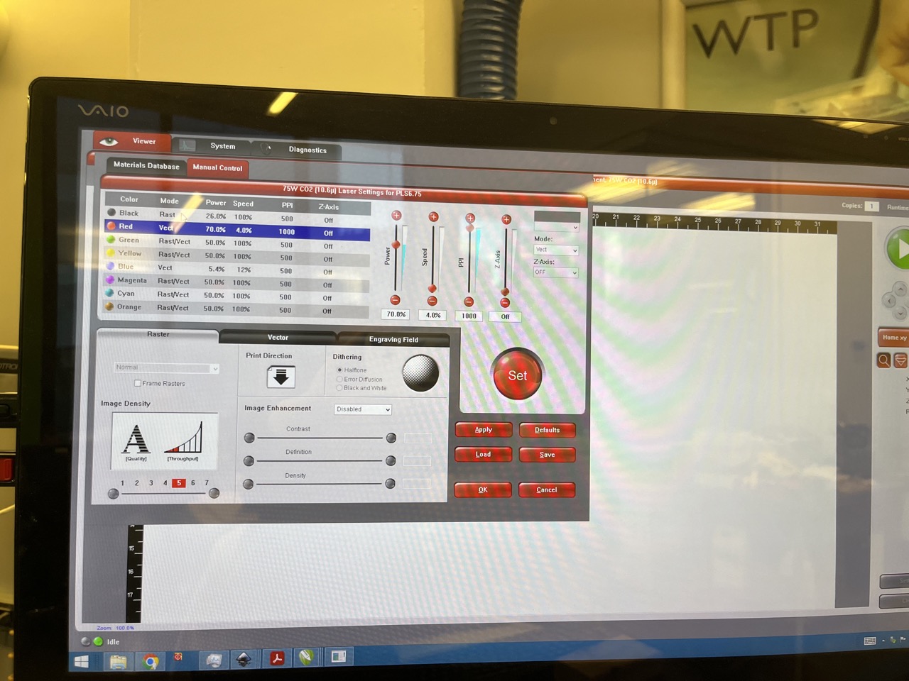
The laser cutting process went smoothly.
Next, we tested the compatibility of our designed and cut bearings with the gear. The testing was a success, as seen in the following video:
We also tested the smaller gear:
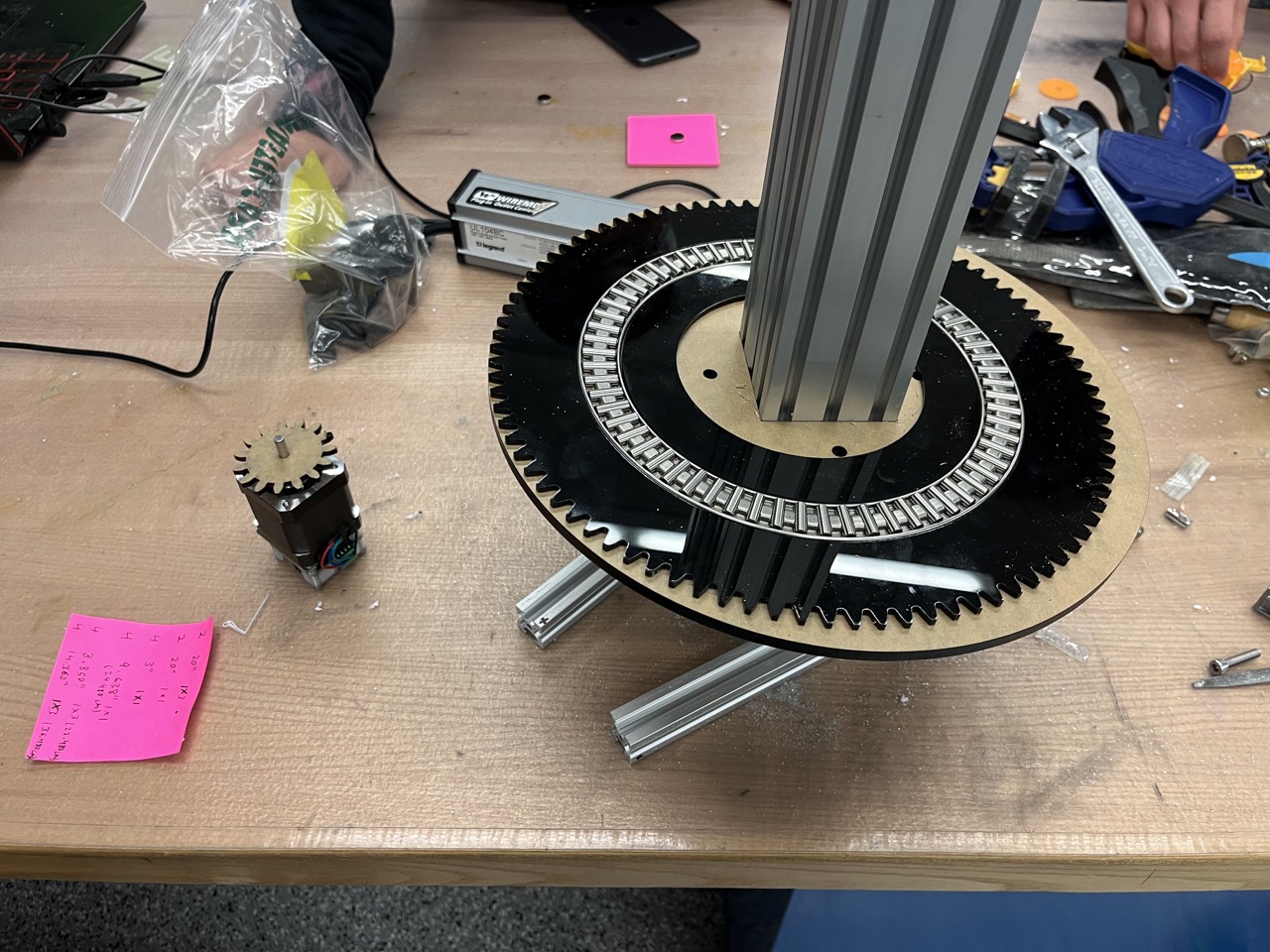
Below is the fully assembled gear and bearing system, along with the servo motor that rotates the table:

While working on the gear assembly, we also cut aluminum extrusions to create the base and assembled them using the provided brackets:
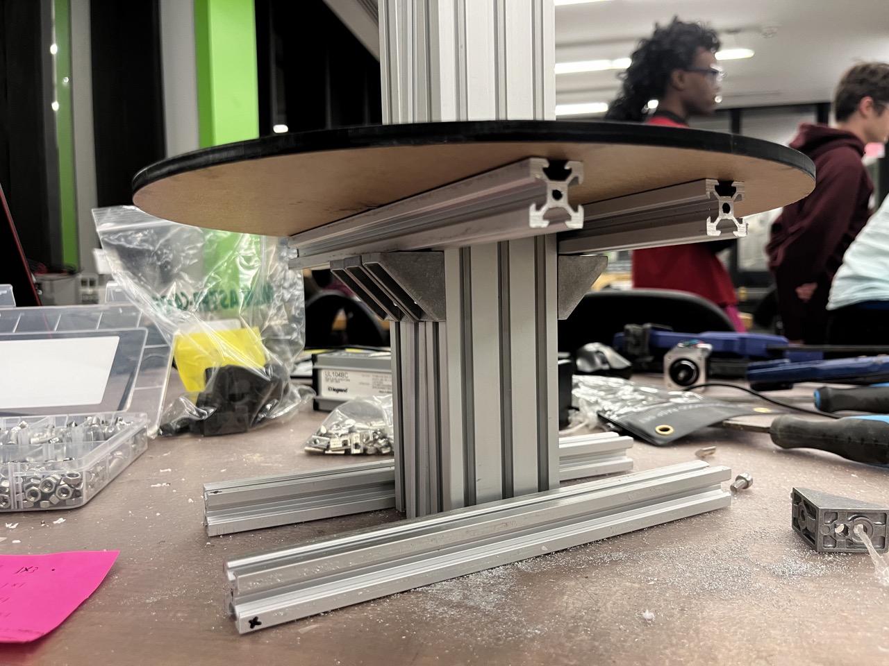
The initial assembly with the gears and bearings is shown below:
A major discussion within the team revolved around the material for the large turn table. Wooden materials were initially ruled out due to their incompatibility with liquids. Acrylic was considered but eventually dismissed due to its fragility. After careful evaluation, we chose plywood treated with beeswax for water resistance. JD sourced the plywood for us (if you need plywood, contact JD!). The plywood was machined using a CNC machine:
After machining, we sanded the table:
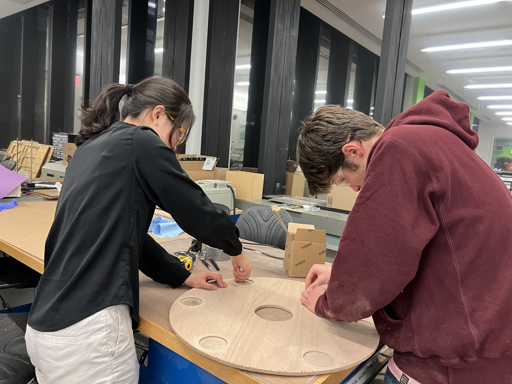
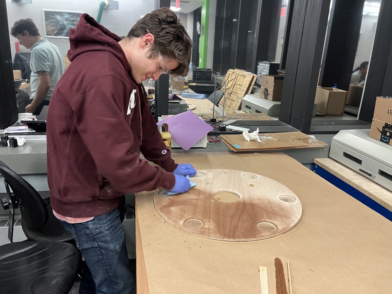
We treated the plywood with beeswax to enhance water resistance:
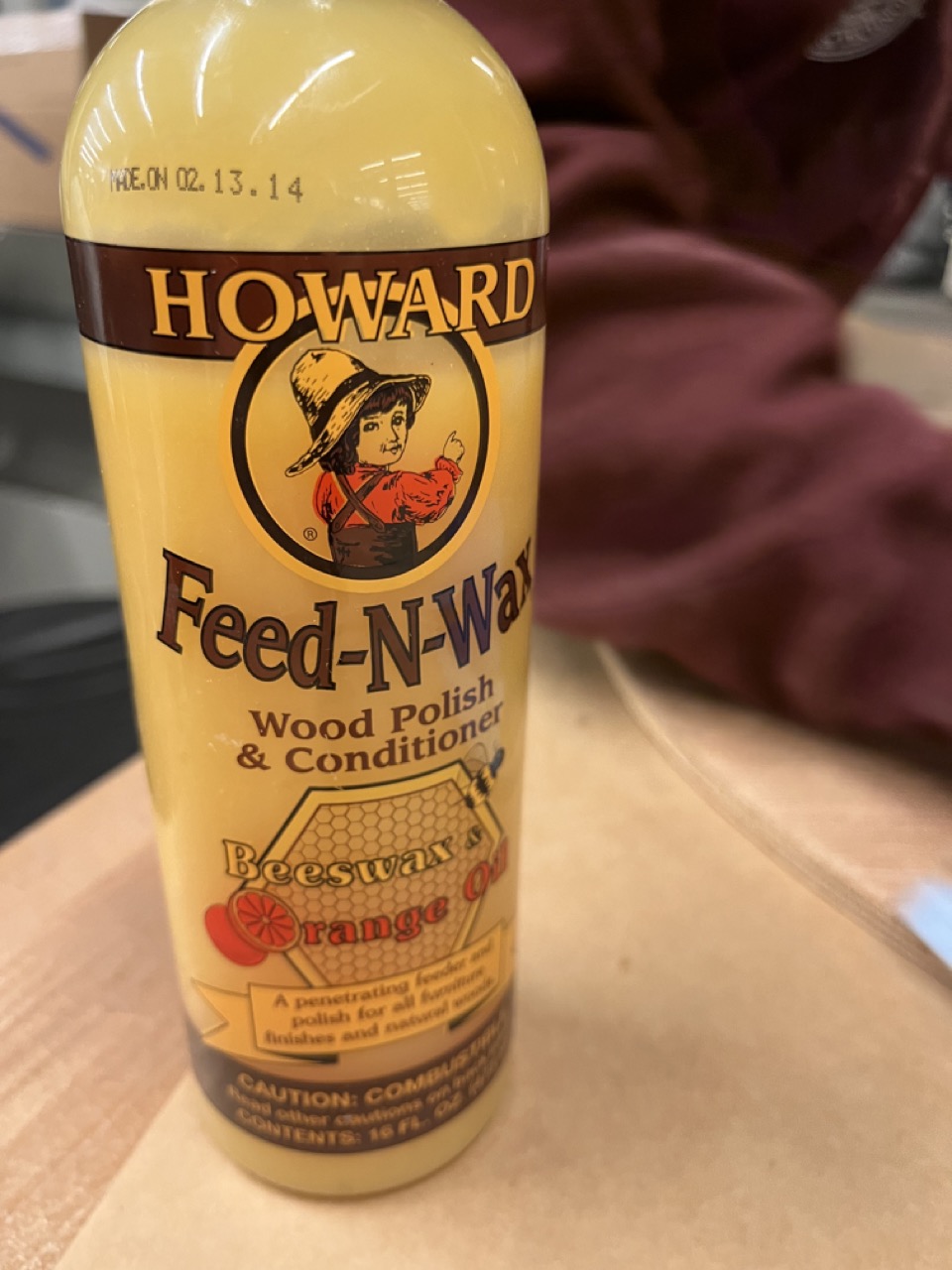
Beeswax is easy to apply—simply pour a small amount onto the wood and spread it with a paper towel. It cures quickly, which was ideal for our project.
Finally, we tested the table top with the gear and bearing system. The hand testing went well, as shown in the video below:
After tirelessly assembling the turn table, we decided to use our custom motor control instead of the default H-bridge motor provided in the kit. Below is the first test of the turn table with our motor control:
Electronics
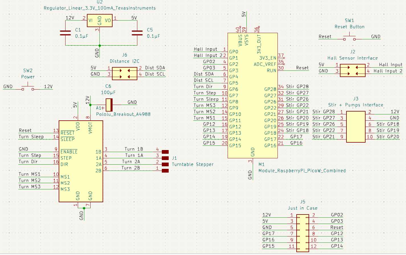
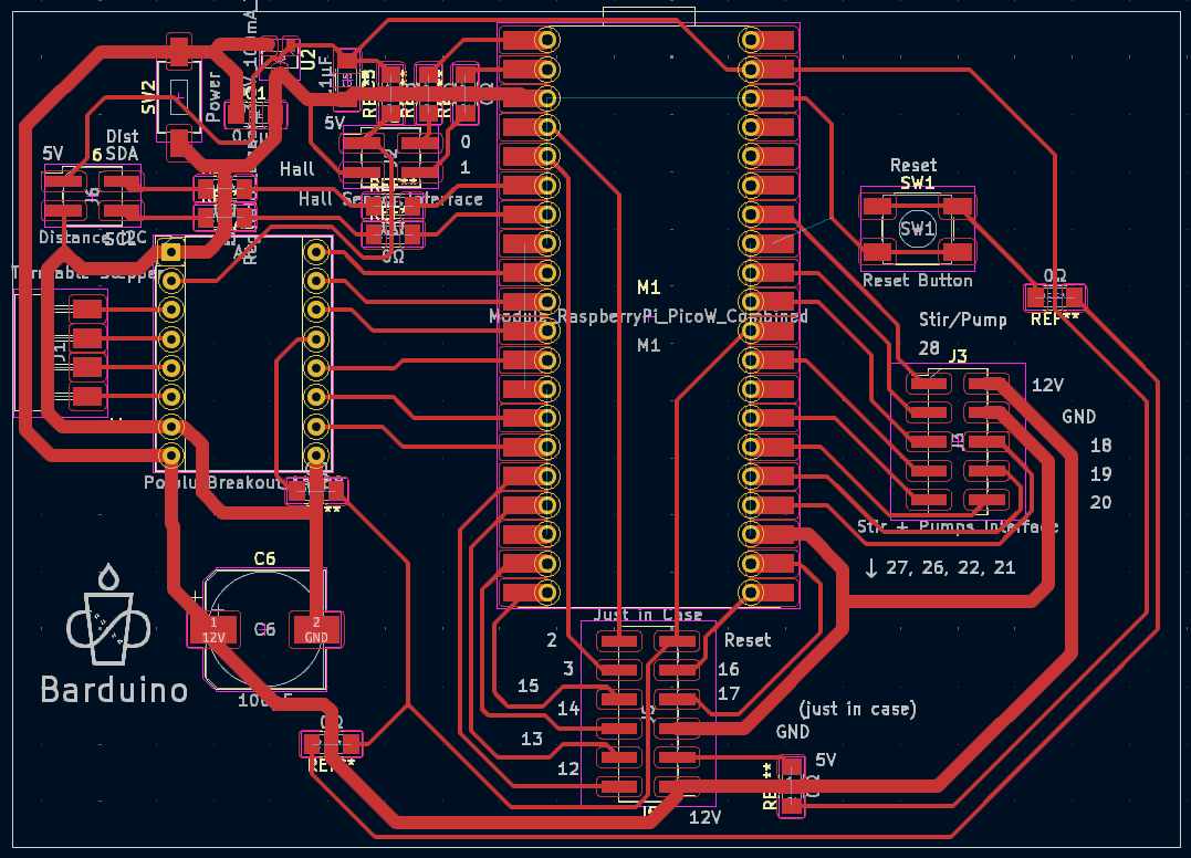
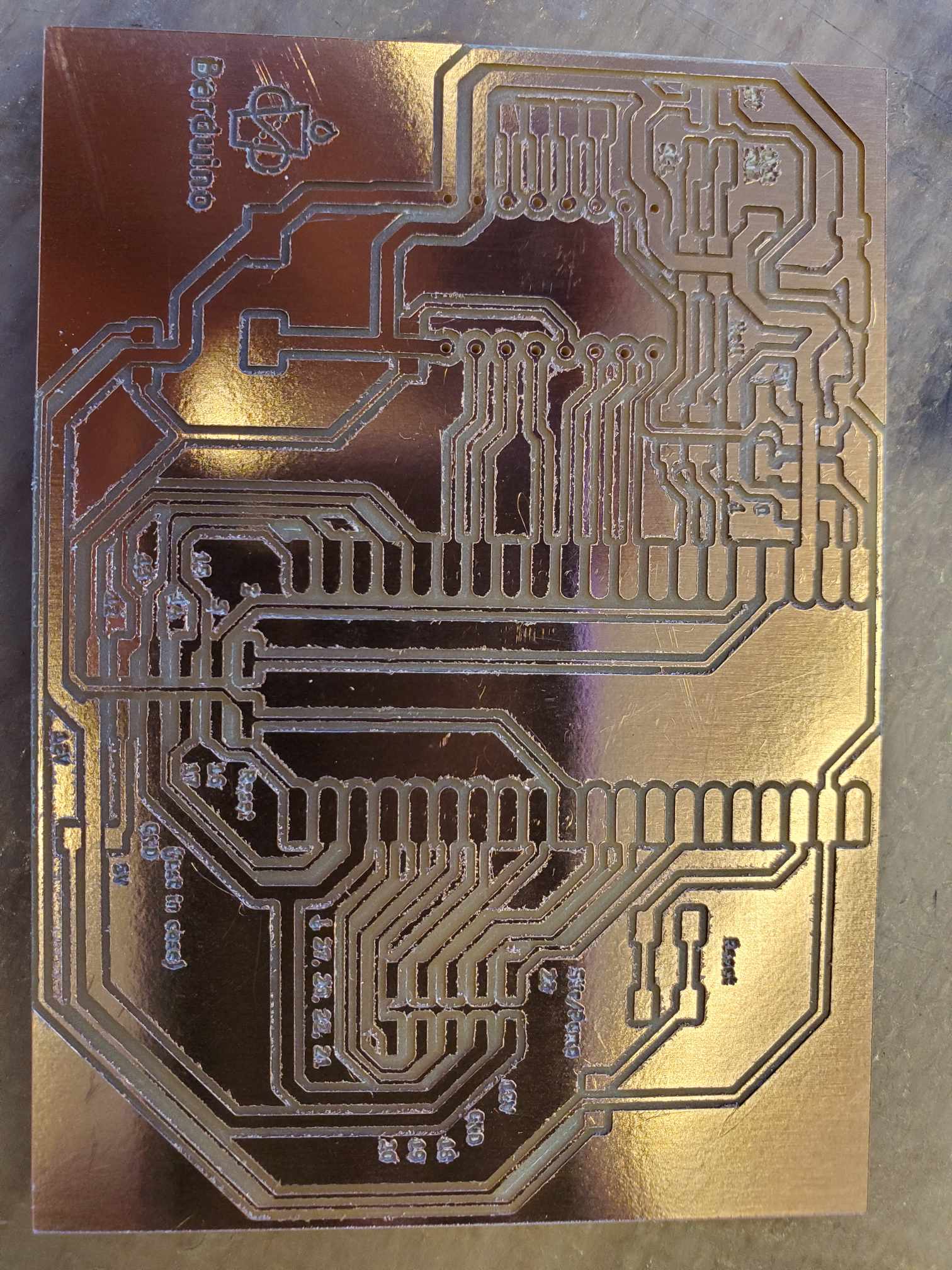
This section highlights the work done by different team members on the electronics, particularly the design of the project’s main board.
Main board schematic:
Main board PCB layout:
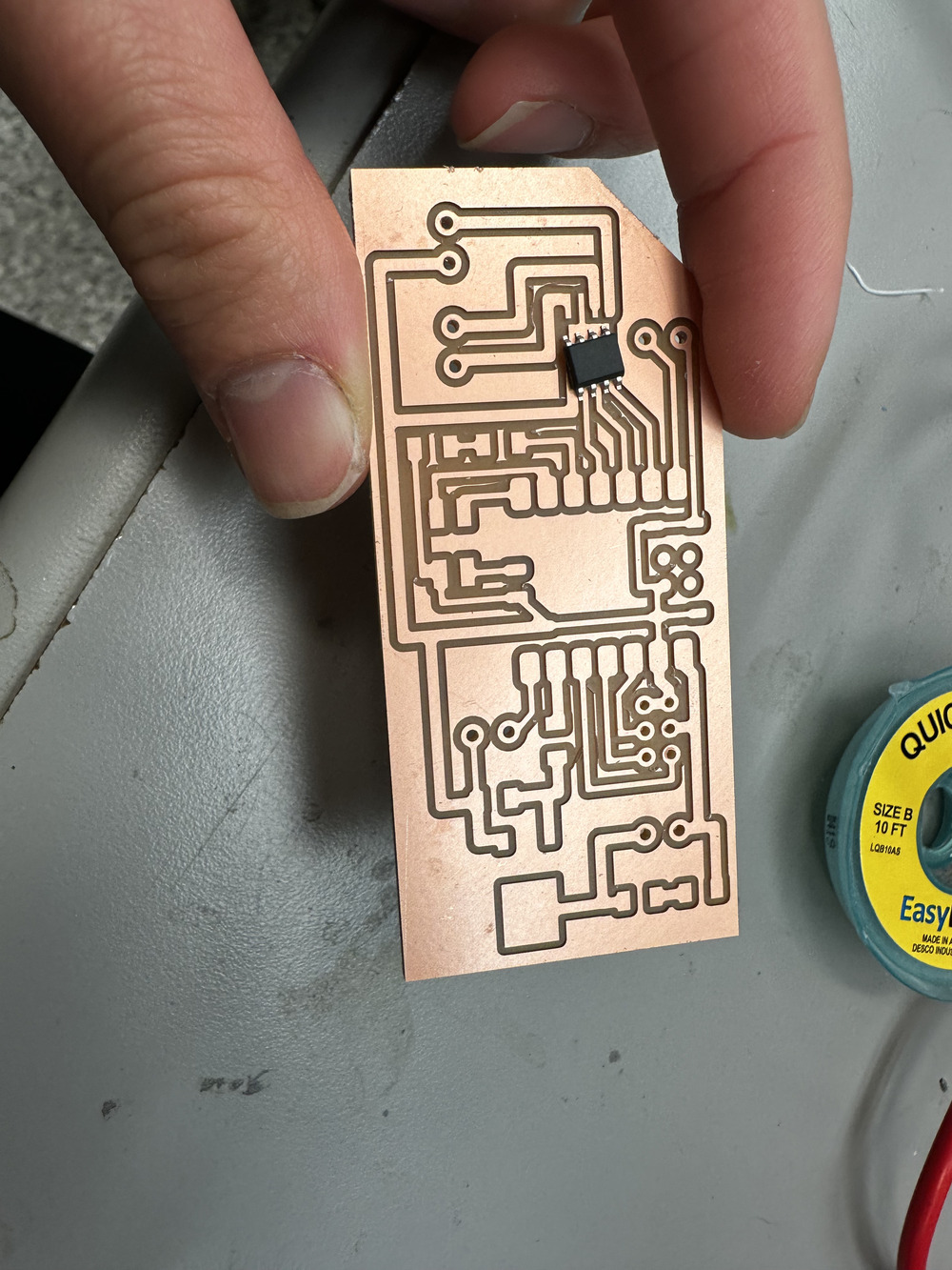
The main board after milling:
UI Control System
Cup Detection
