This week's assignment was to incorperate input devices into my microcontroller workflow. My initial idea was to create an automatic schedule printer, or to do list utilizing a thermal receipt printer and Google's API. I bought the Adafruit Mini Thermal Printer online - note that it has been discontinued.
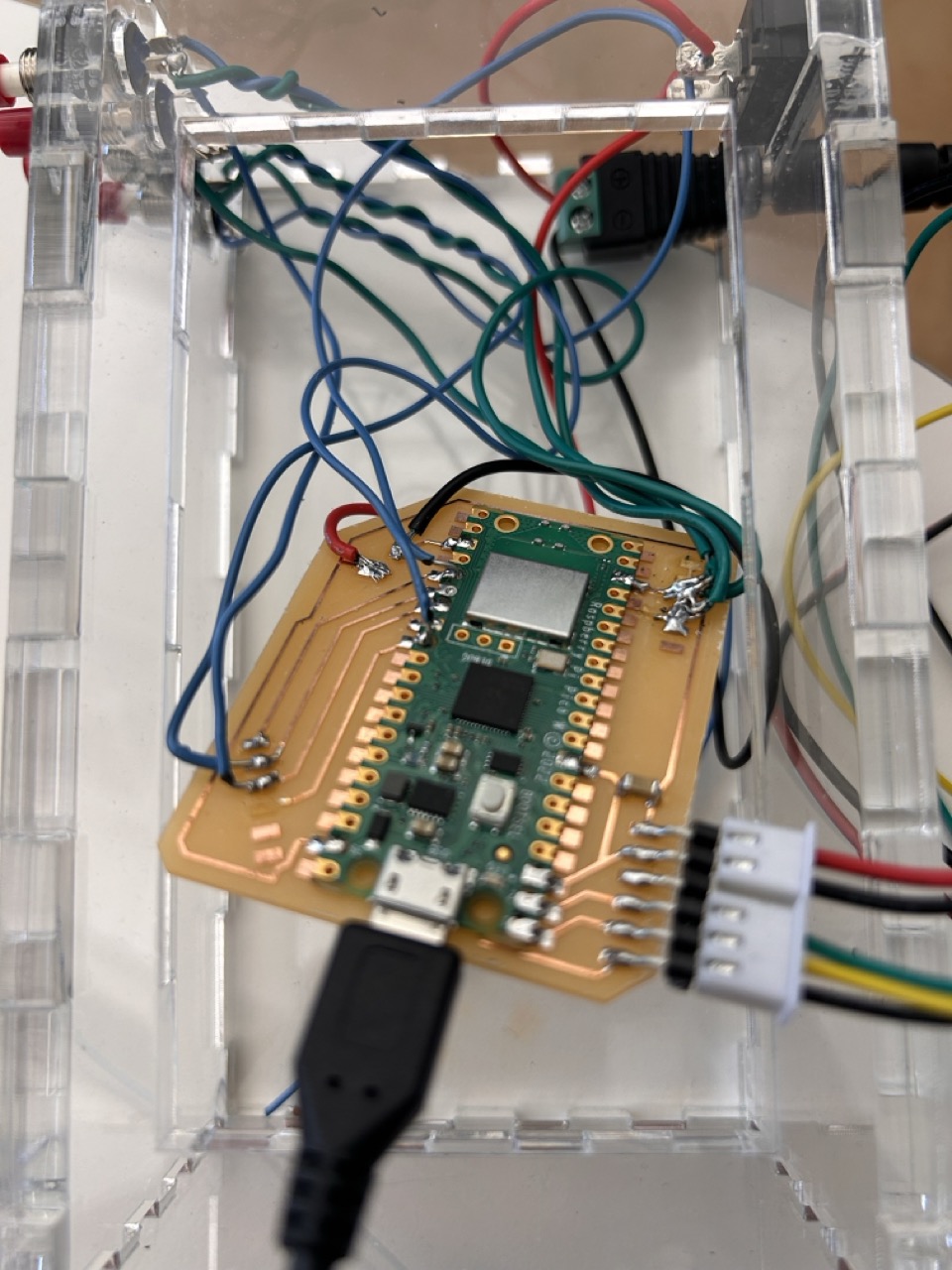
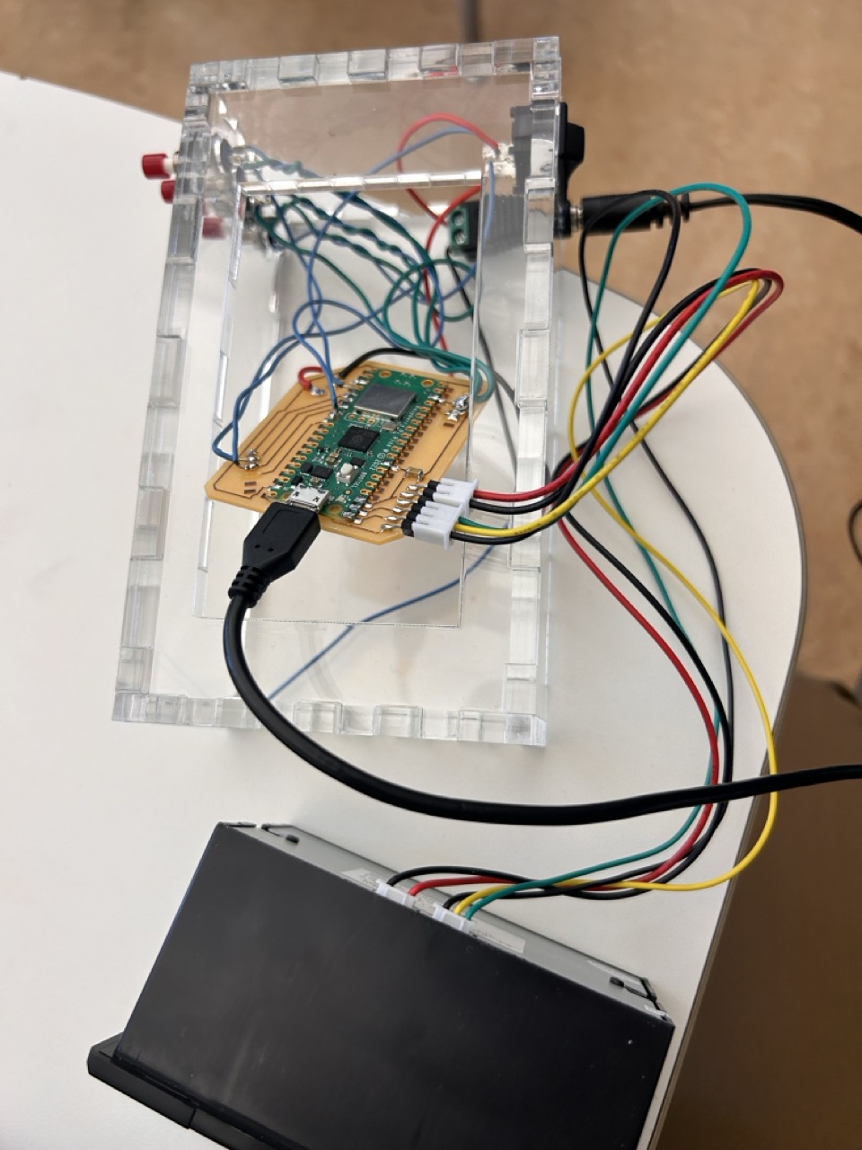
My intent is to build an acrylic finger joint box with a custom PCB, 4 buttons and an external power source. I am very keen on making projects look professional, rather than a bird nest of wires. For this project, I was only moderately successful. The final hardware certainly is not production ready, but I have definitely learned a lot through this process about the different connectors and electronic components availible.

This is the acrylic box cad rendering. I worked hard to *finally* make this parametically modular - to include the joints. You can see in the below picture of the various parameters I used in this design. This has definitely been an iterative process to ensure that I didn't break the box as soon as I changed one parameter like length or width. Specifically, in this design I codified the number of joints (at 10) and defined the size of the joint by a function of side length.
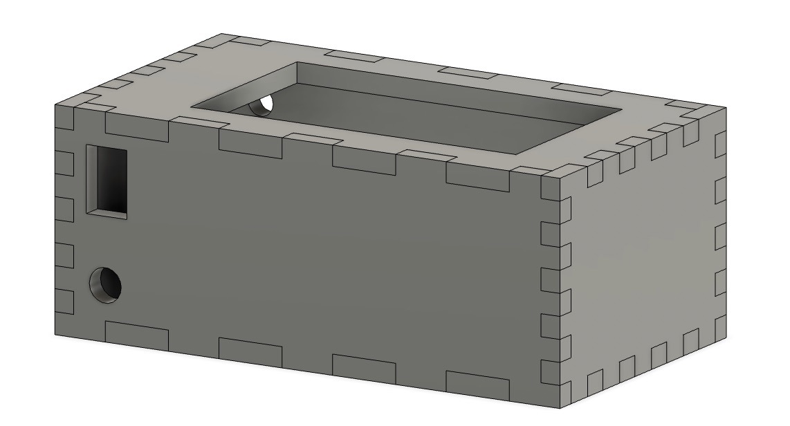
Back of the box. I used calipers to ensure a tight fit with a switch, barrel jack, buttons, and drop-in window for the printer head.
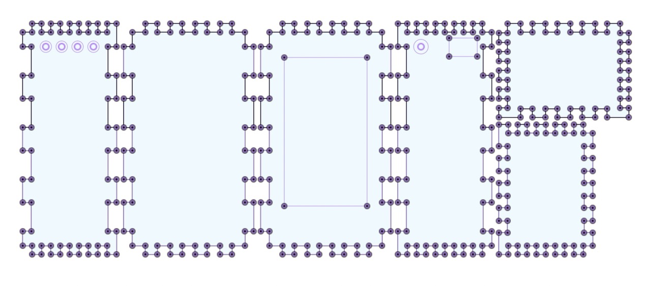
Box sketch. I offset each profile by 1/2 kerf. In my inital box, I used a kerf of 0.25mm (roughly 0.010 inch); however, this was *just* too tight and split the acrylic with the friction fit joint. I reduced the kerf to 0.24mm which resulted in a perfect fit (through, I think 0.23mm would be perfect)
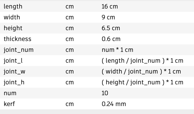
These are a list of the parameters.
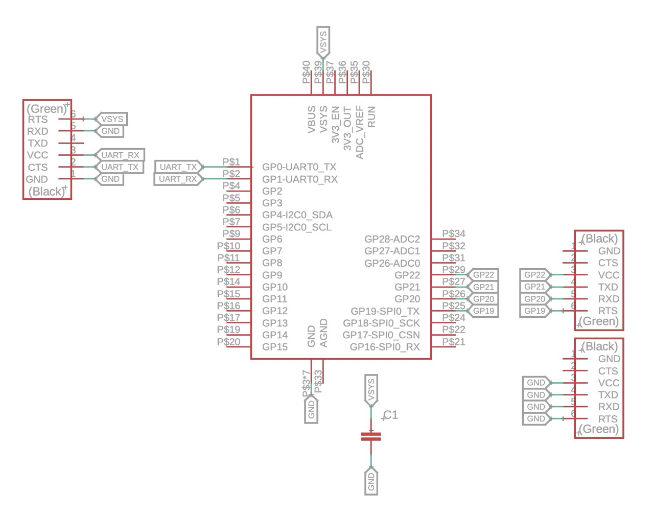
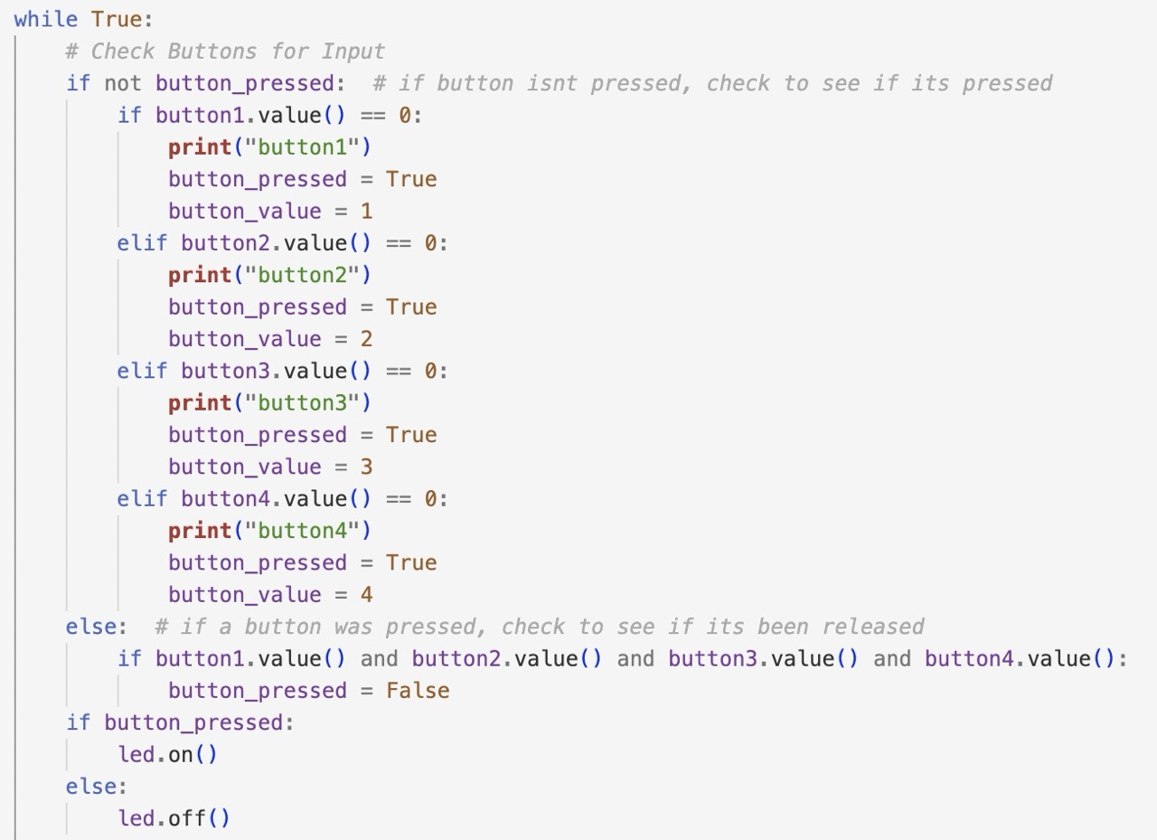
This is the circuit schematic. I'm incorperating four buttons, connected to the PICOs gpio, and ground - utilizing the innate pull-up resistors in the PICO. The receipt printer utilizes a 5V, 2A power supply and a standard UART. I broke out these pins on the top left of the board, though I didn't have the JST connectors the printer came with, I used 0.1 inch pitch header pins surface mounted to the board. Additonally, I included a 10uF bypass capacitor.
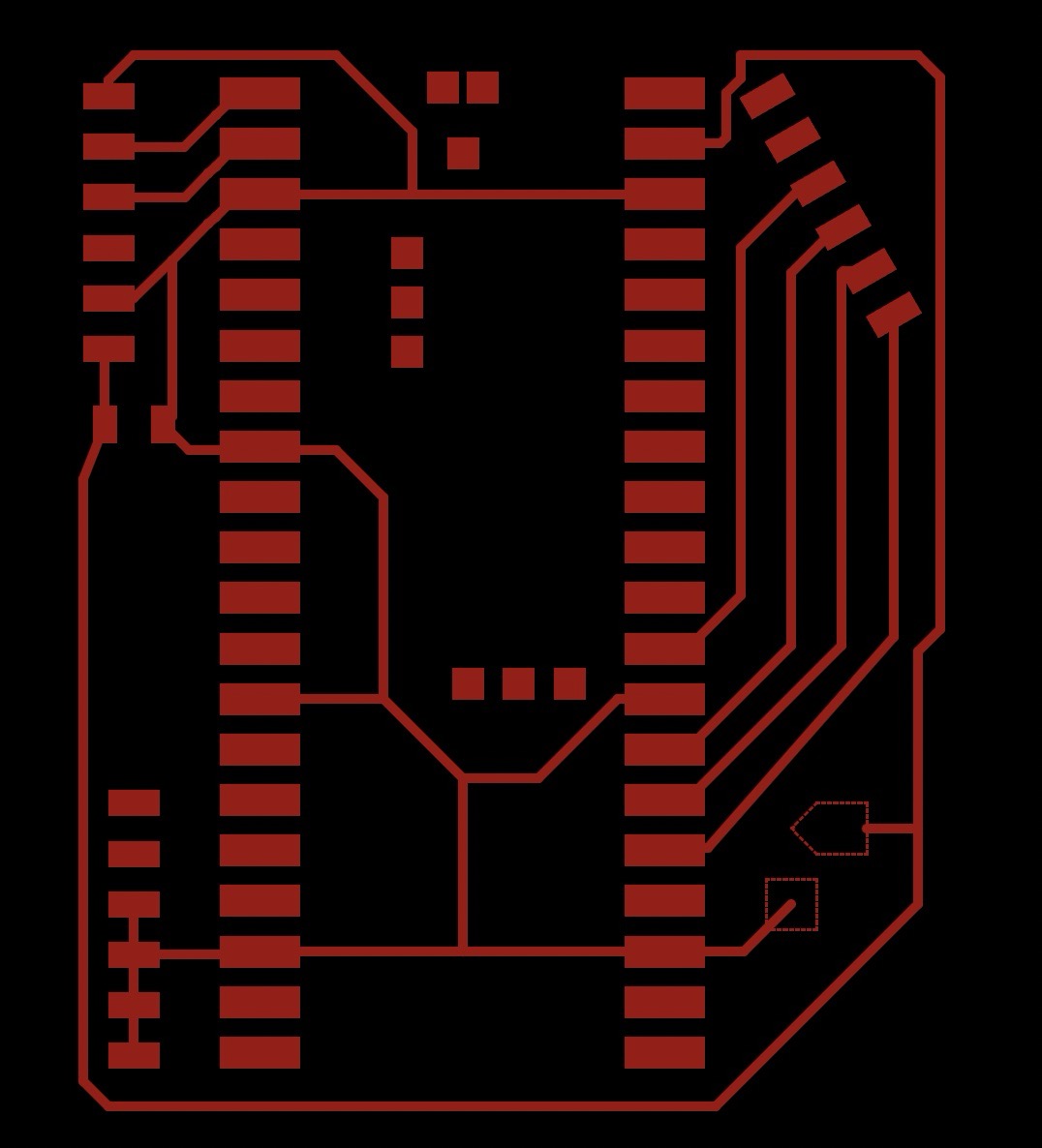
I needed to add two heafty pads on the board for the power interface from the barrel jack. Instead of making a through hole and screw down terminals, I elected to draw my own polygons. I did a house shape for VCC and square for GND.
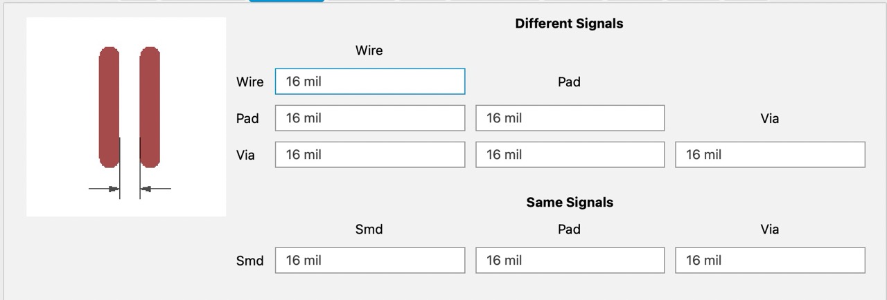
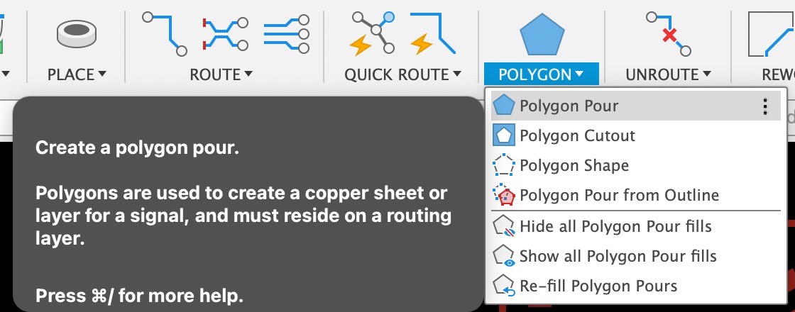
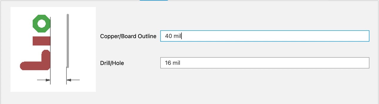
Recapping from electronic design week - make sure to selec the correct EDRs. My first design didnt have this and I had to redo it.


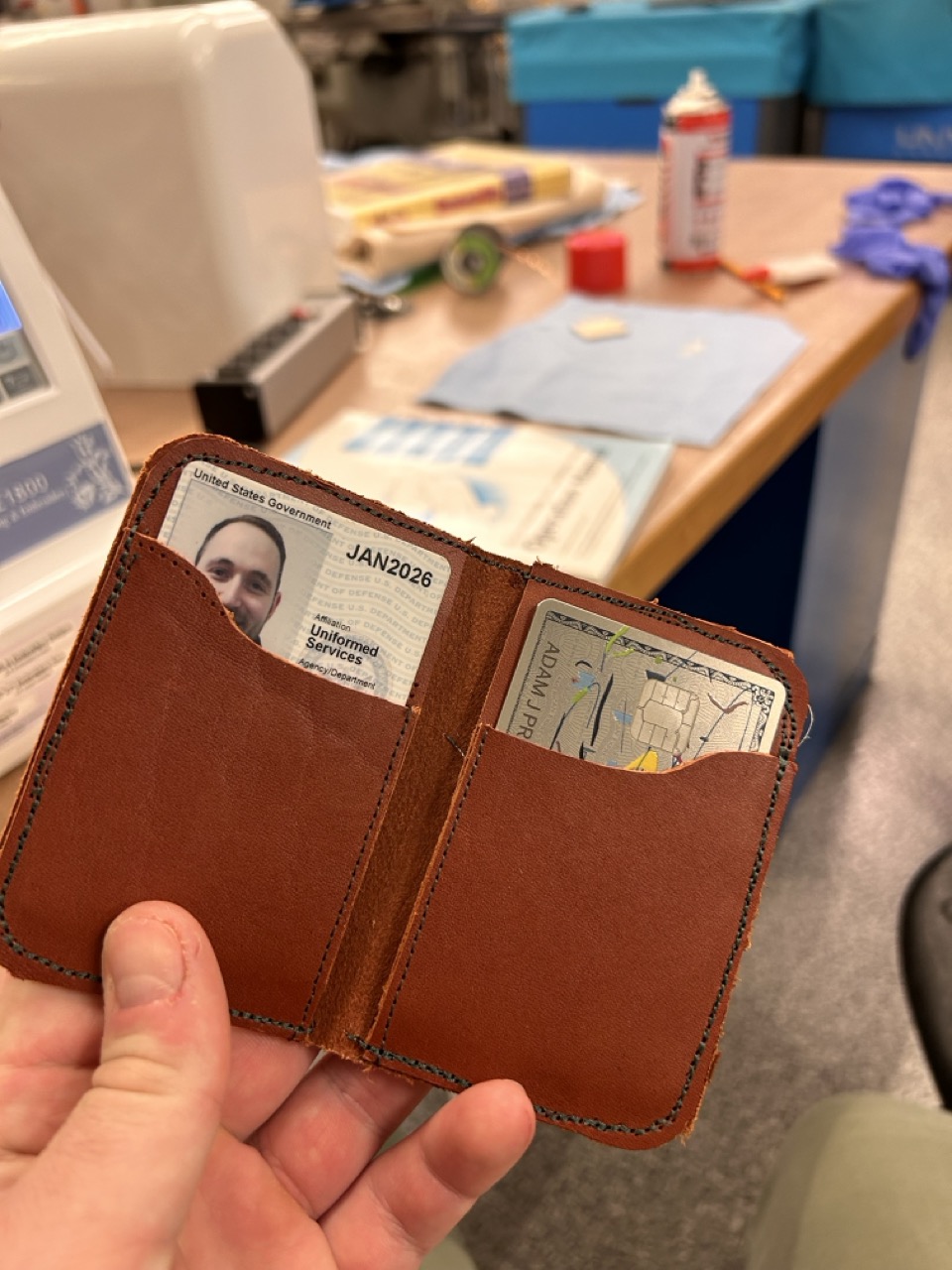
As a bonus! I finished sewing my wallet from the vinal cutting week!