
HTMAA Week 10
Assignment Description:
add an output device to a microcontroller board you've designed, and program it to do something
Output Devices – Hydroponics
This week I continued work towards my final project, an automated watering and feeding system for my two hydroponic gardens. In order to deliver water and nutrients and route reservoir water for EC testing, I need to operate several liquid pumps.
Four pumps used for each garden (2x4 = 8 pumps):
- One Pump from water jug -> garden reservoir
- One Pump from nutrient solution A -> garden reservoir
- One Pump from nutrient solution B -> garden reservoir
- One Pump to/from sensor testing bath <-> garden reservoir
As well as one additional pump from water jug -> sensor testing bath in order to wash the probes
Therefore, I need a total of 9 pumps. I am using these brushed 12V DC peristaltic pumps. I opted for peristaltic pumps because they do not actually interact with the liquid, instead physically compressing the tube.

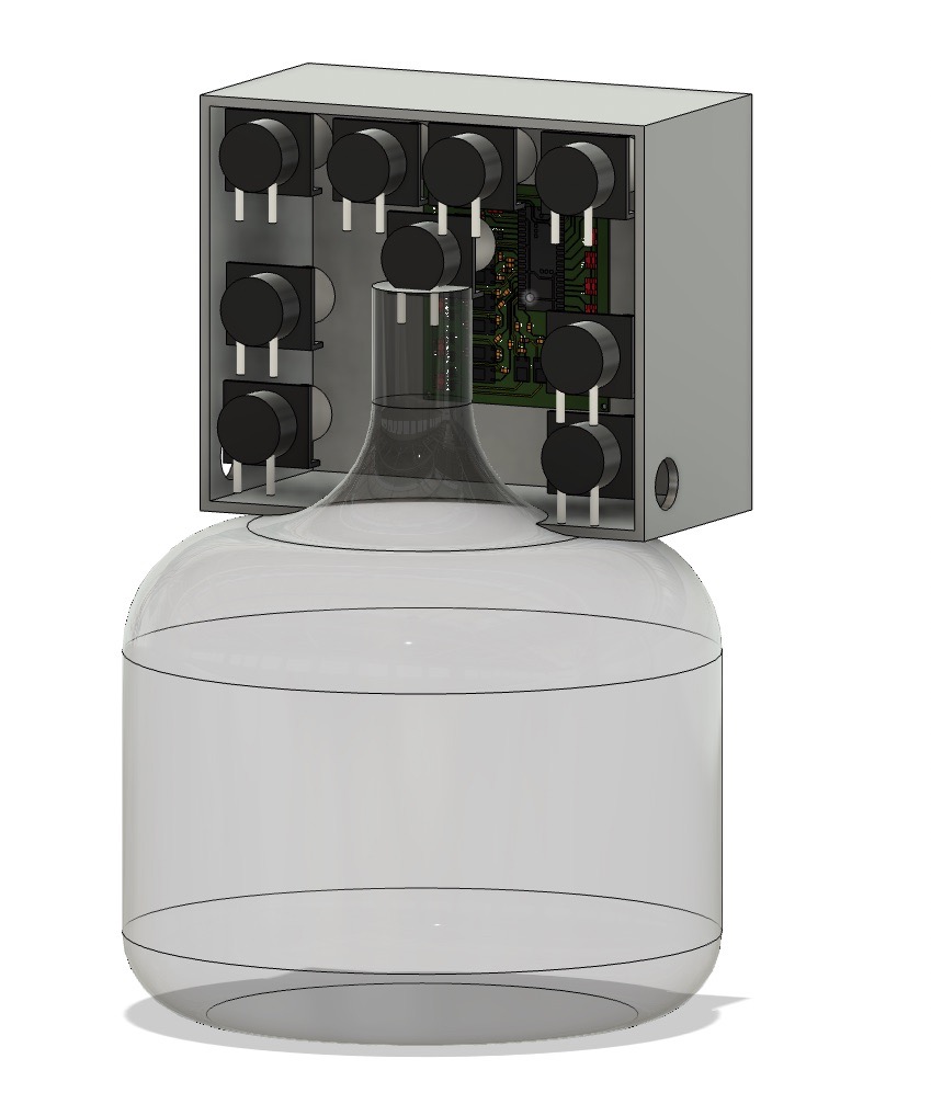
The following is a rough CAD sketch of how I am planning to implement the pump housing for my final project:
Designing the Board
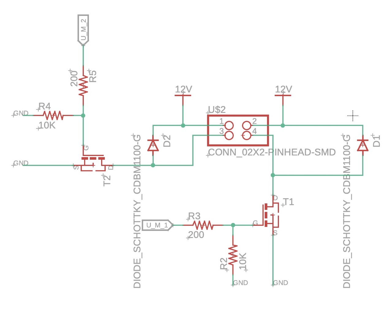
In order to drive even one pump, much less 9, I needed to design a new board in order to provide 12V to the pump motor. To toggle power to the motor with the logic voltage (3.3V) from the Pico, I needed an N-channel MOSFET. The following is the circuit I used to control the unidirectional pumps. It is duplicated twice over to utilize the 2x2 pin header.
Moreover, I utilized the TB67H451AFNG H-bridge in order to drive the two bidirectional pumps.
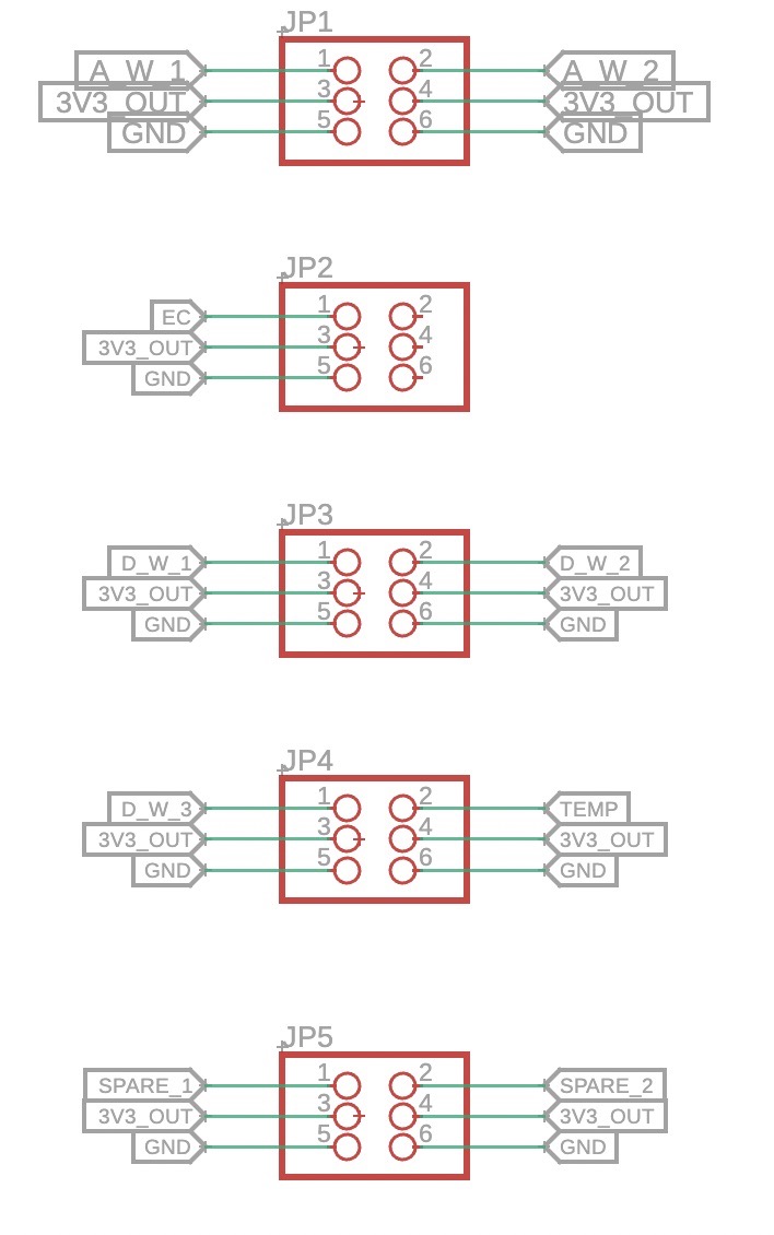
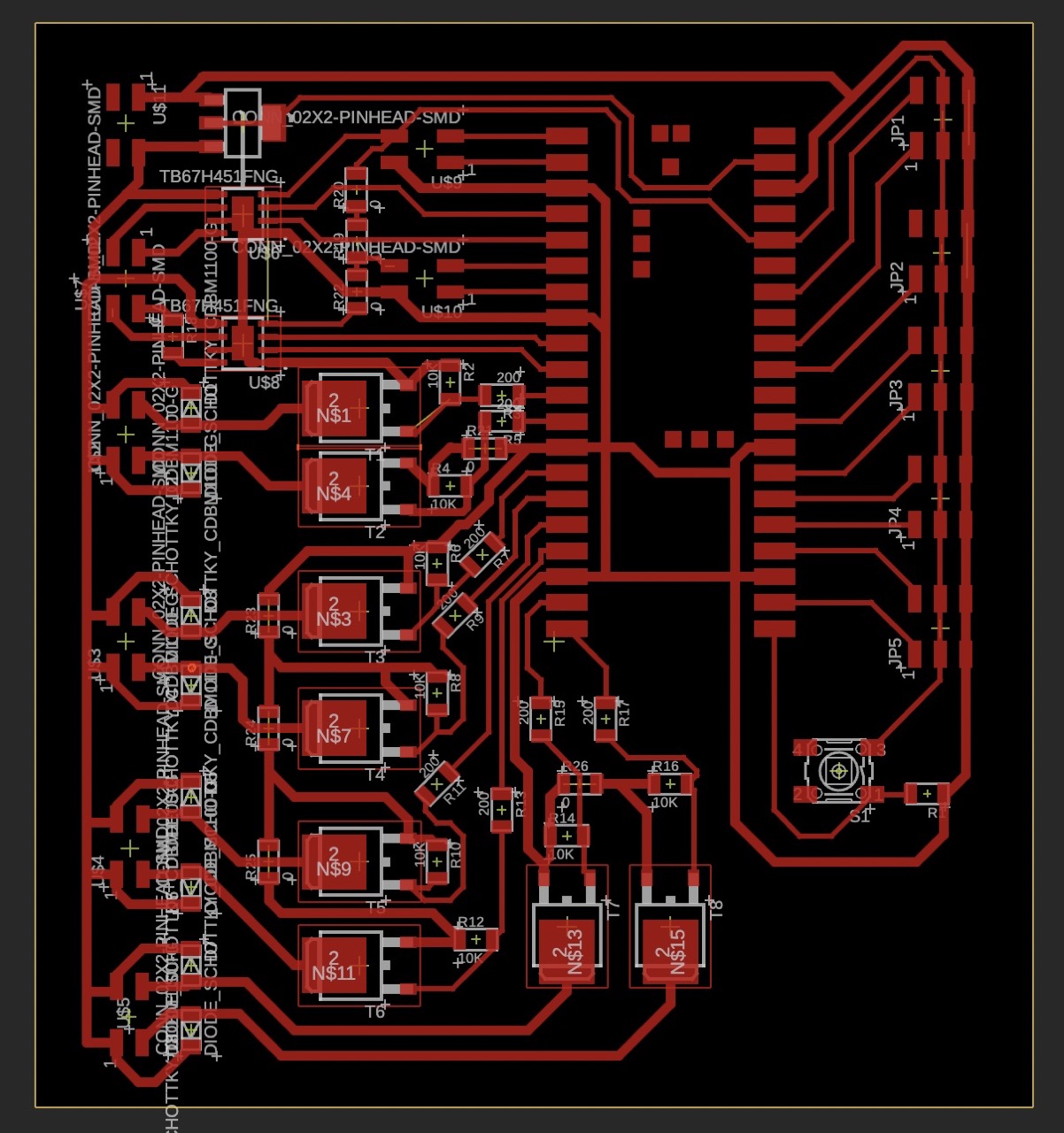
I designed the board with the intention of future proofing it for use down the line in my final project, so I reserved the right side of the board (as that is where the analog pins are) for inputs:
Routing this board was quite the challenge and took several hours. The large components (MOSFETs, H-Bridges) took up quite a bit of space and made routing especially difficult. Navigating GND and 3V3 were the most difficult, and required the use of several 0 Ohm resistors to jump traces.
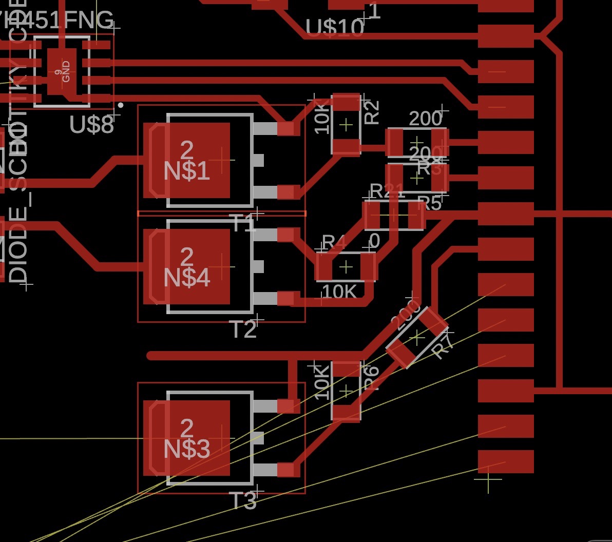
The following is the final design:
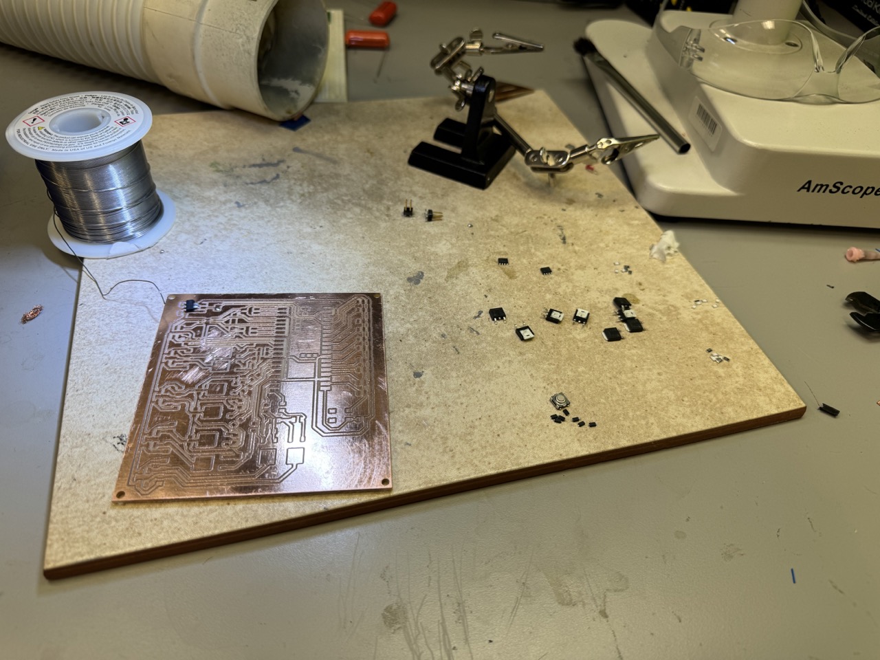
Milling
As I did in week 6 I used the Othermill to mill the traces for my board.
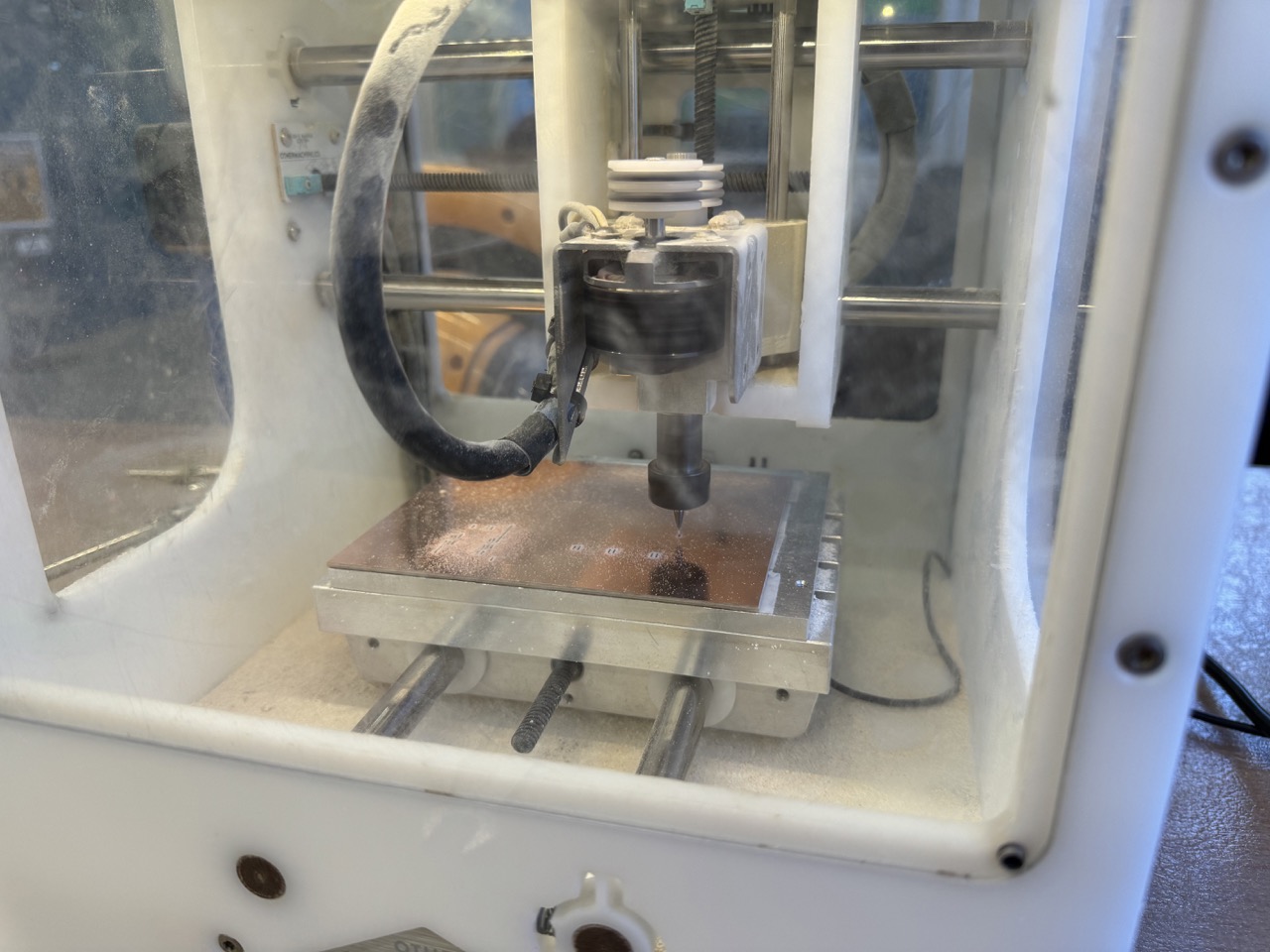
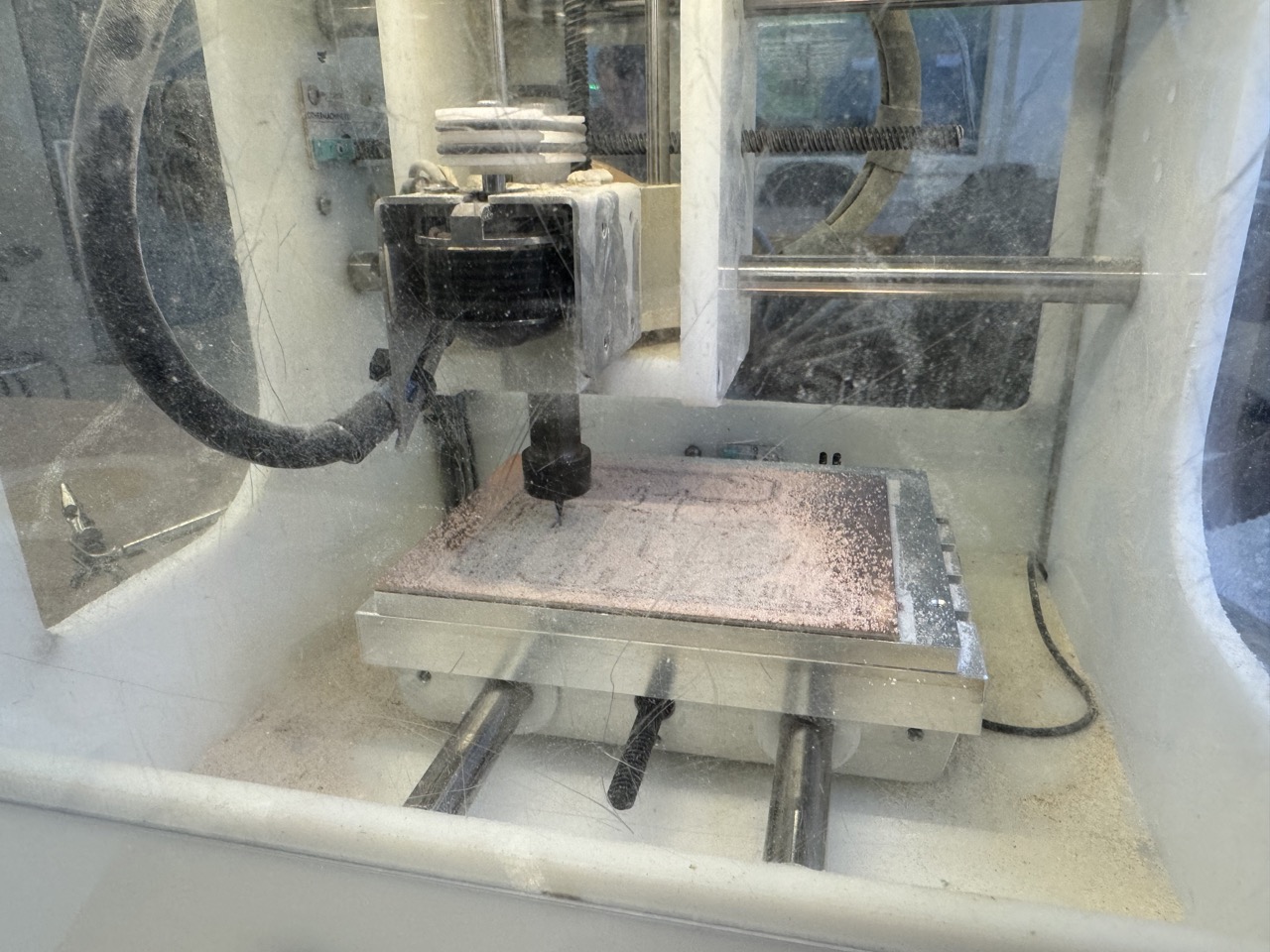
The 1/32 endmill was pretty dull, so it chewed up the board pretty good and left a rough finish.
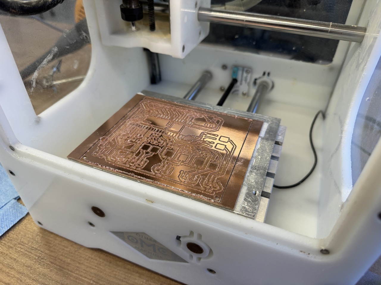
After some time with sandpaper, it cleaned up pretty nicely.

Soldering
Before soldering, I perused the component cabinets and found each of the components I needed. We were out of 200 Ohm resistors, so I went with 100 Ohm ones instead. I *think* that should be okay. We also only had 150 mA diodes, which I think will be okay given that the current draw of the pumps is on the order of 80 mA. I started with the smallest components (resistors and diodes) to make it easier. This took forever and I probably should have used reflow. This experience inspired me to learn.

Finally, I had my finished board:

Pico Setup
Because I was using a fresh Pico, I needed to install MicroPython. No problem, right? I went through the installation process within Thonny, and then wanted to test my connection by flashing the onboard led. I tried loading GPIO25, I tried loading "LED", and everything the guides online said, but no dice. Then I found this forum thread that mentioned installing the MicroPython firmware by hand over the file system. Then, it worked like a charm!
Testing the Board
There are many functionalities to test on this board, but given that this is output device week, I tested my ability to control both bidirectional and unidirectional pumps.
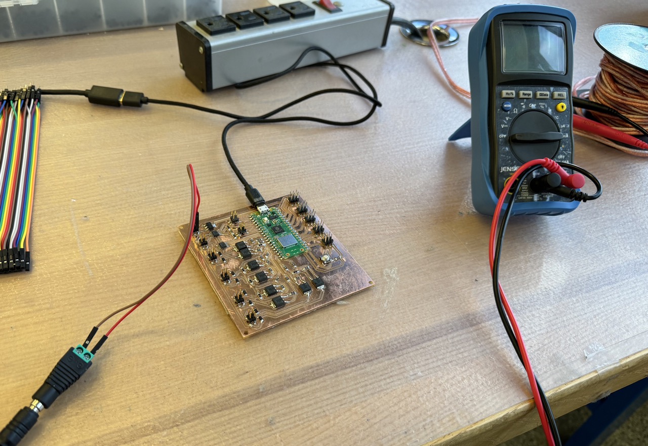
N
Note: The above problems were resolved as I continued work on the final project. It turns out the barrel jack was not making a solid connection, leading to power issues. By slightly bending the center spine of the power jack, it made a solid connection, and power was good. In the below videos, the pumps are actually running off of the 5V from USB, leading to the poor flow rate. I describe many other changes to the board including the aforementioned diode on my final project page.
Then, I tested the H-bridge's ability to switch the pumps in both directions:
There was a little stutter within the motor, so I inspected the board and realized I forgot to solder one of the pins to the board!
Finally, once at home I tested the pumps ability to ... pump!
(Again, this is at 5V, not their rated 12V, leading to this poor flow rate. This is fixed in the final project)