
HTMAA Week 6
Assignment Description:
Make and test the development board that you designed in week 5 to interact and communicate with an embedded microcontroller
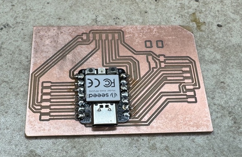
Assembled Board
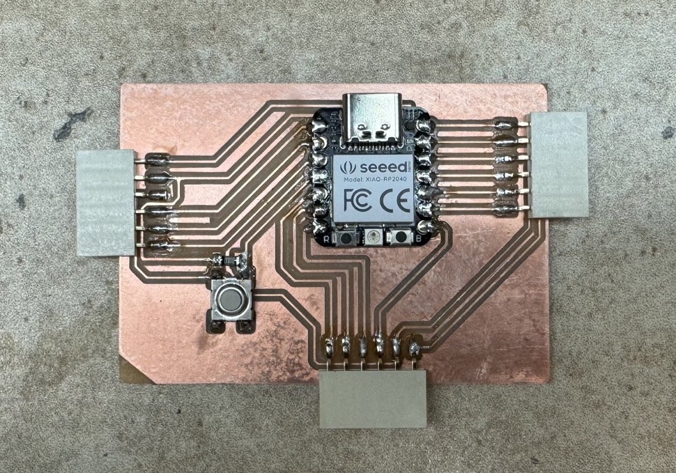
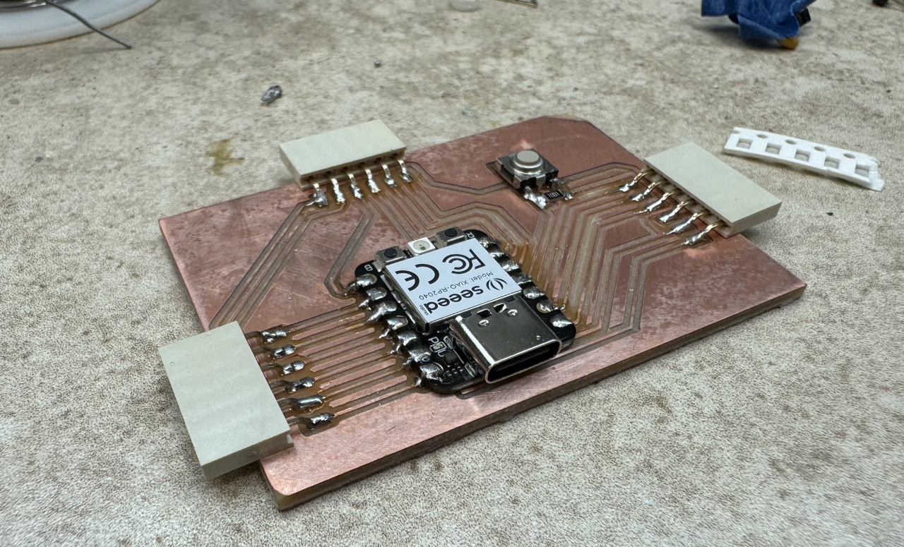
This week I milled and assembled my first ever circuit board!
Last week I designed a development board for the seeed studio RP2040 Xiao, a microcontroller powered by Raspberry Pi's RP2040 chip capable of running MicroPython.
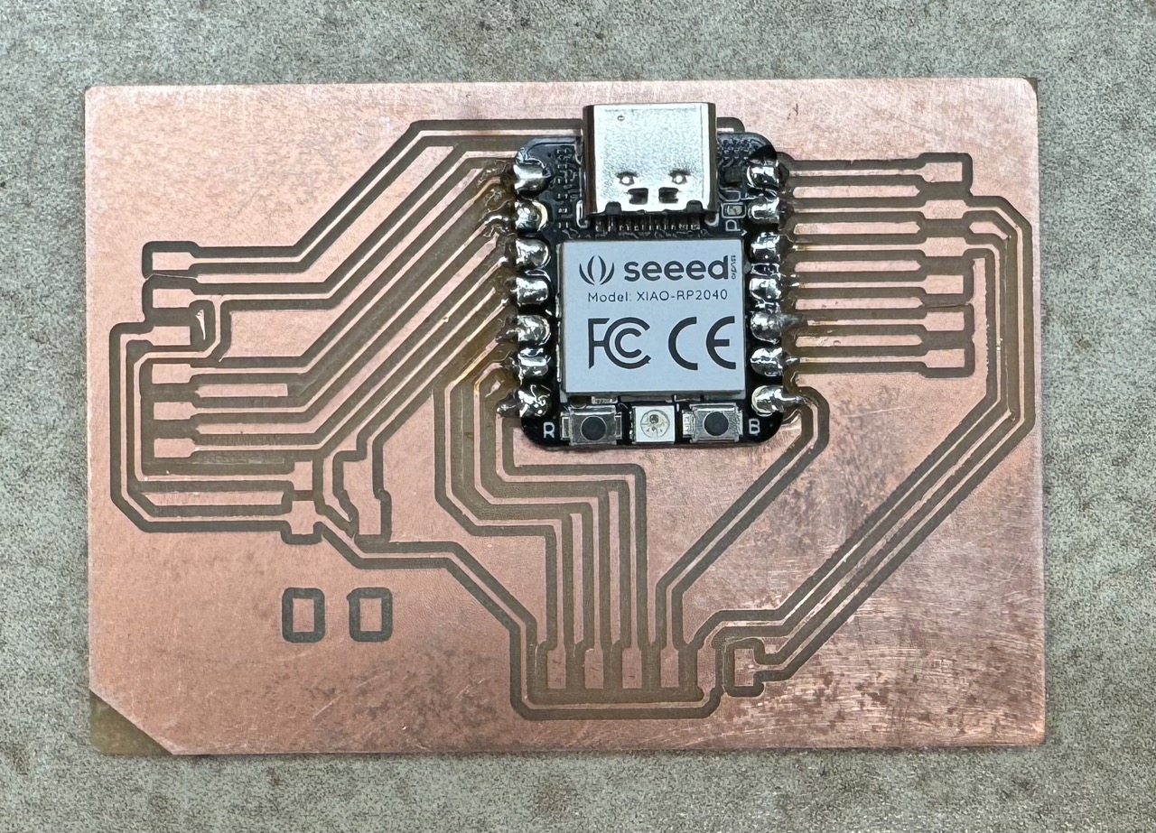
Pinout
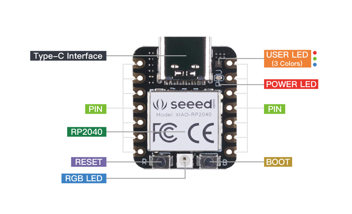
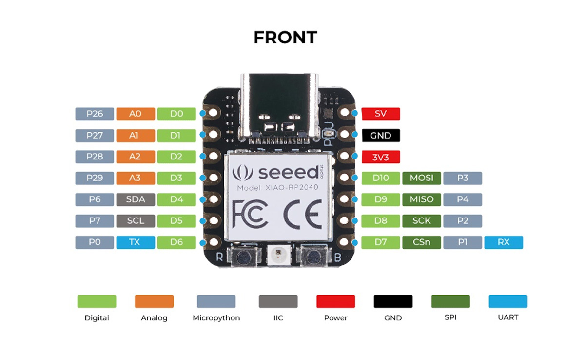
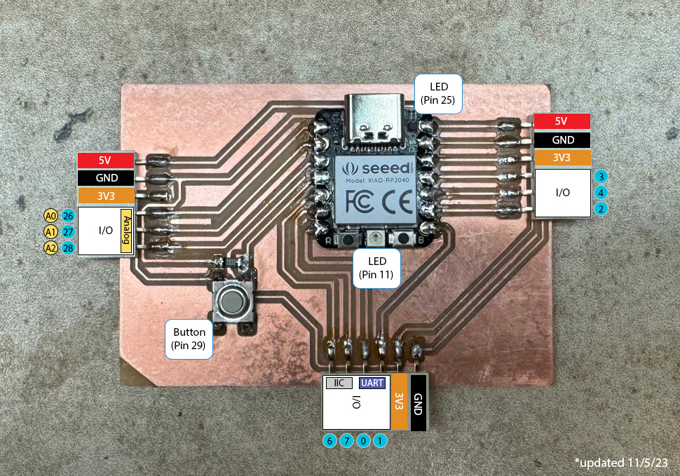
The aim of the board is to "break out" the RP2040's pins into a usable interface for external components, as well as add a button for simple user interactions and testing. The following shows the completed board with its pins labeled. By following the traces one can see where each pinout originated on the board and its label from the datasheet. I plan on using MicroPython, so I am using its pin numbering convention.
Milling
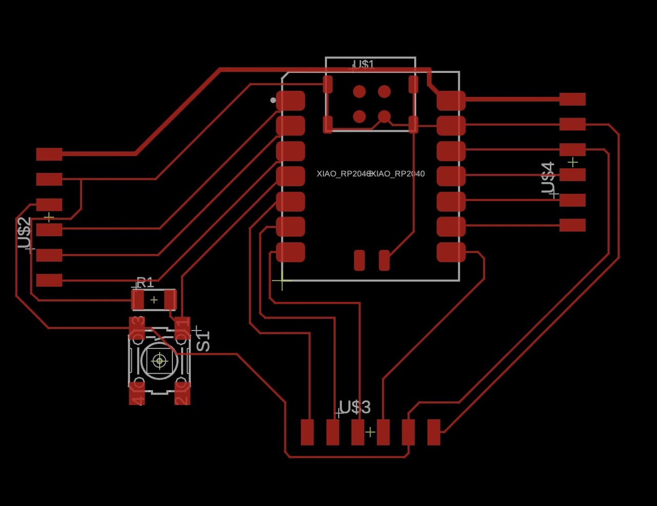

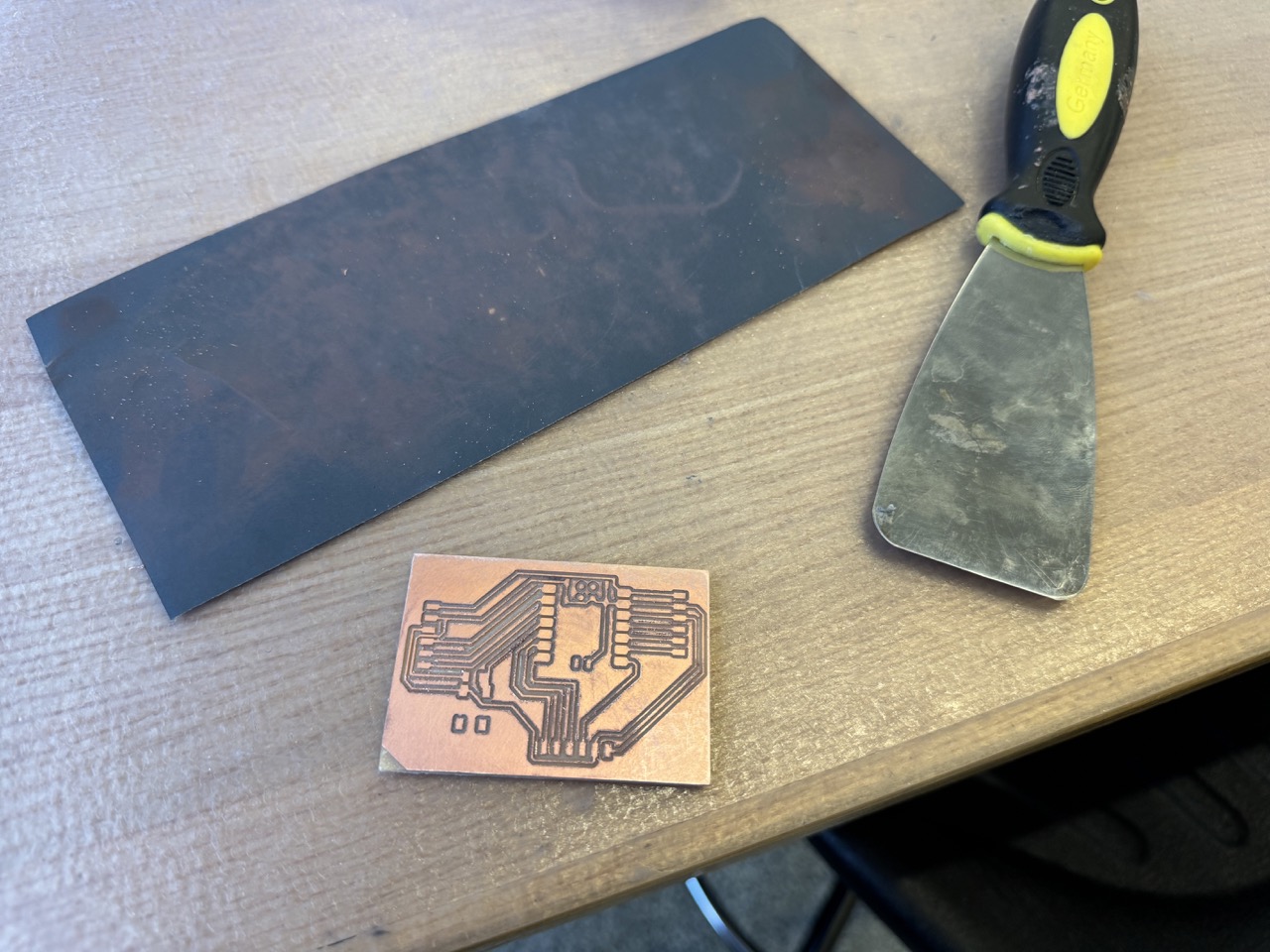
Per Anthony's recommendation, I used the OtherMill to mill the board. It was extremely easy to use! Walking through the process with Anthony, he noted that my traces were too narrow, so I widened each of them to 16 mil. The notches within the microcontroller pads were too tight for the 1/32 bit, so the board required a pass with the 1/64 bit. Note that the 1/64 bit container also has "1/32" printed on it, so be sure to check the smallest number on the package, which is the actual tool diameter. After a couple of quick changes, the board was milled in about 10 minutes.

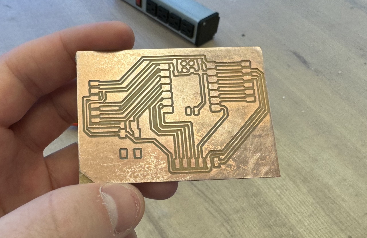
The 1/32 bit had seen better days, so the initial product was extremely rough and three-dimensional (the photo above was taken after a few minutes of cleanup with the spatula). Per Anthony's recommendation (once again) I carefully ran the metal spatula parallel to the traces to clear the largest bits. Next, I put the board face down on some fine-grit sandpaper and rubbed it around in circles. Finally, a few blasts of compressed air got rid of the remaining junk.
Assembly
After cleaning up the bare board, I heated up the soldering iron to begin the assembly process. I have soldered in the past, but not with components this small on a brand new board. Neil's tip about letting the iron rest on the junction for 10 seconds to heat them up before introducing the solder served incredibly useful. Moreover, I maintained a shiny tip to avoid gunky solder as much as possible.
After soldering a few connections, I was getting the hang of it. Once I soldered each of the Xiao's pins, I added the button and the 1K pull-up resistor. Tweezers were a necessity for placing the itty bitty resistor.
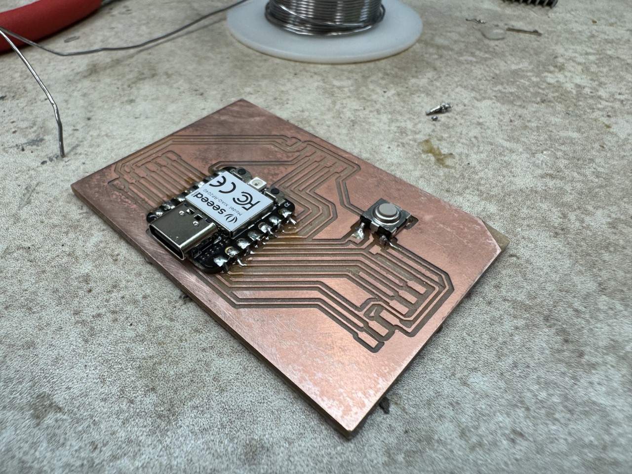
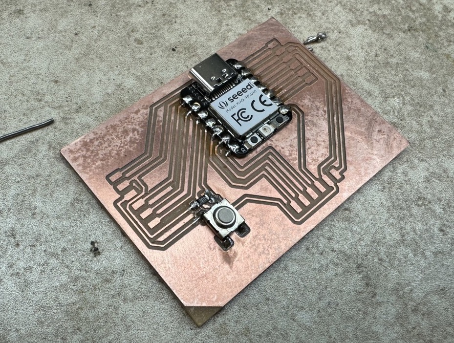
Finally, I added the three pinout interfaces. I opted for female connectors as having male pins stucking out/up everywhere seemed like a recipe for getting poked and pins getting bent.
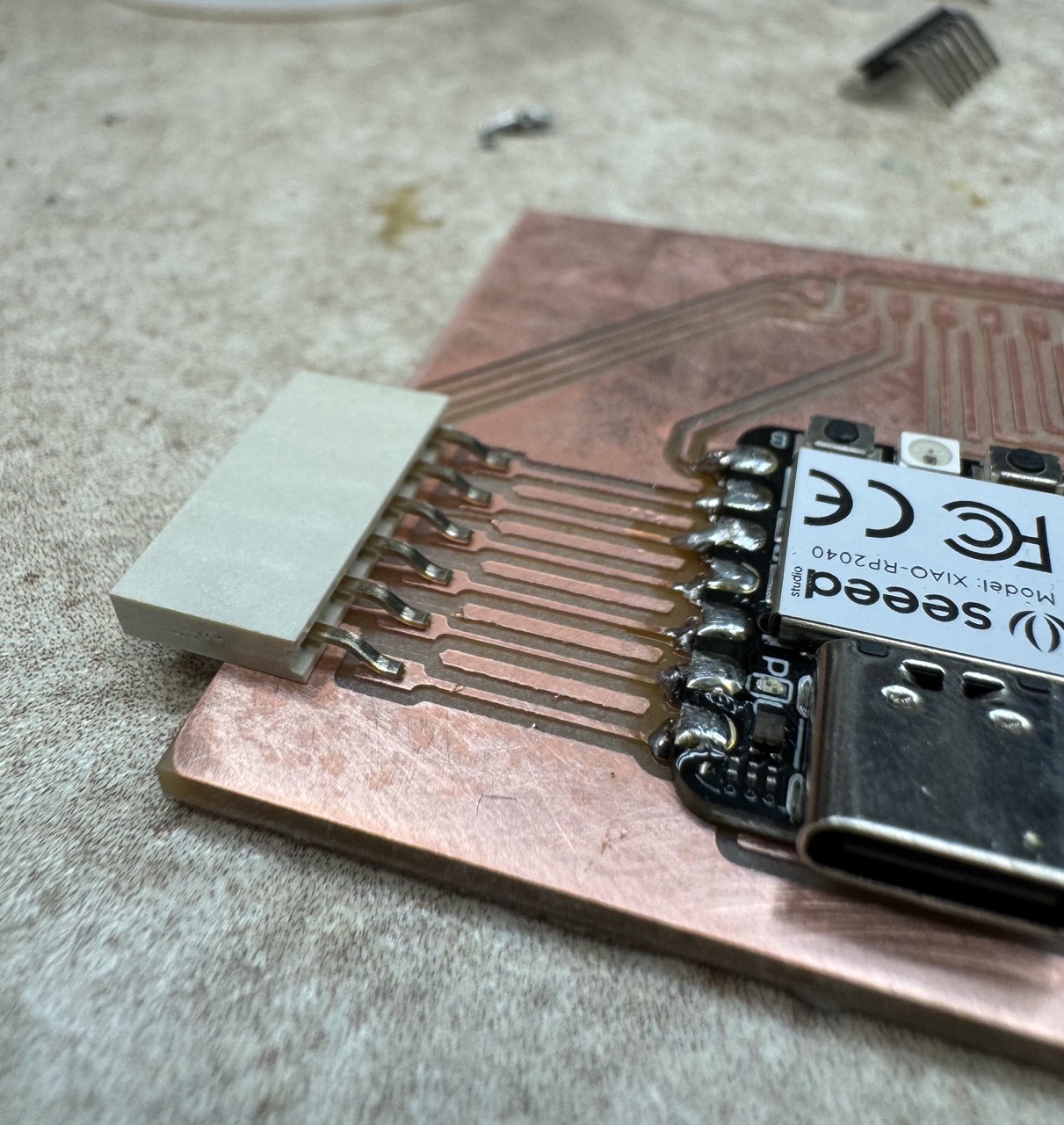

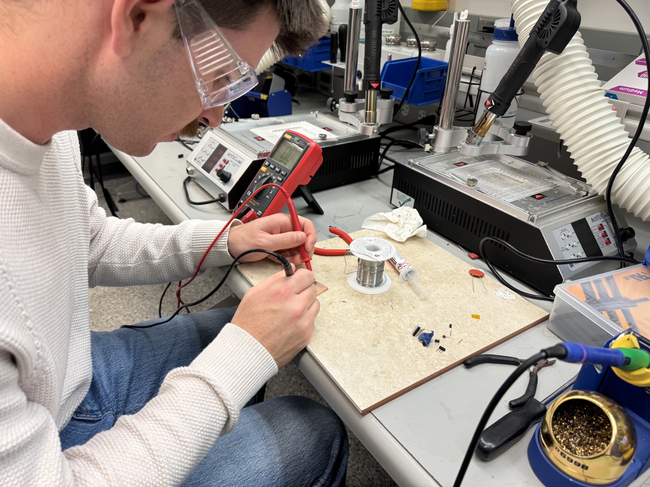
In order to test the connections I soldered, I used the resistance setting on a digital multimeter to make sure everything was connected as it should. I placed the probes on various combinations of pins, pads, and traces. The connections averaged about 20 Ohms, which I considered a success.
Testing in Micropython
Since I used a separate Raspberry Pi Pico W during microntroller week, this was a fresh RP2040 that I needed to set up. This guide from Seeed showed how to install MicroPython to the board via Thonny. I then ran the provided file and tested the RGB led's functionality.
This verified the microntroller was working and that I could interface with it via Thonny over USB. However, I still needed to test that the board I had assembled was functional.
I wrote a MicroPython program that checks if the onboard button has been pressed by polling pin 29. Because the button pin is connected to the 3V3 line and utilizes a pull-up resistor, it is normally "high" in the resting state and will read "low" when it is pressed and connected to ground. A button press then causes the onboard LED to light up, confirming the functionality of at least the board's button. Therefore, the functionality of the button is controlled via software and can be customized depending on the running program. In future weeks, and as I continue to develop my final project, I will utilize the pinouts to interact with external components.