Final Project
Nothing like spending a semester automating something that takes 1 minute a day
(AG)2 - The AeroGarden Auto Gardener
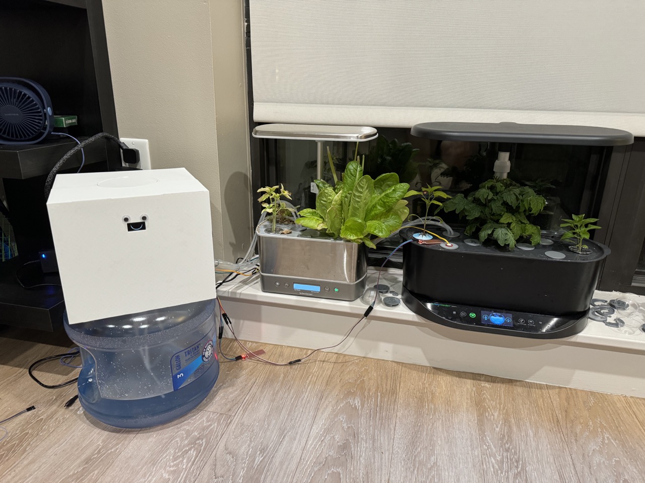
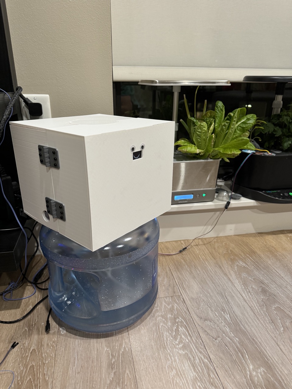
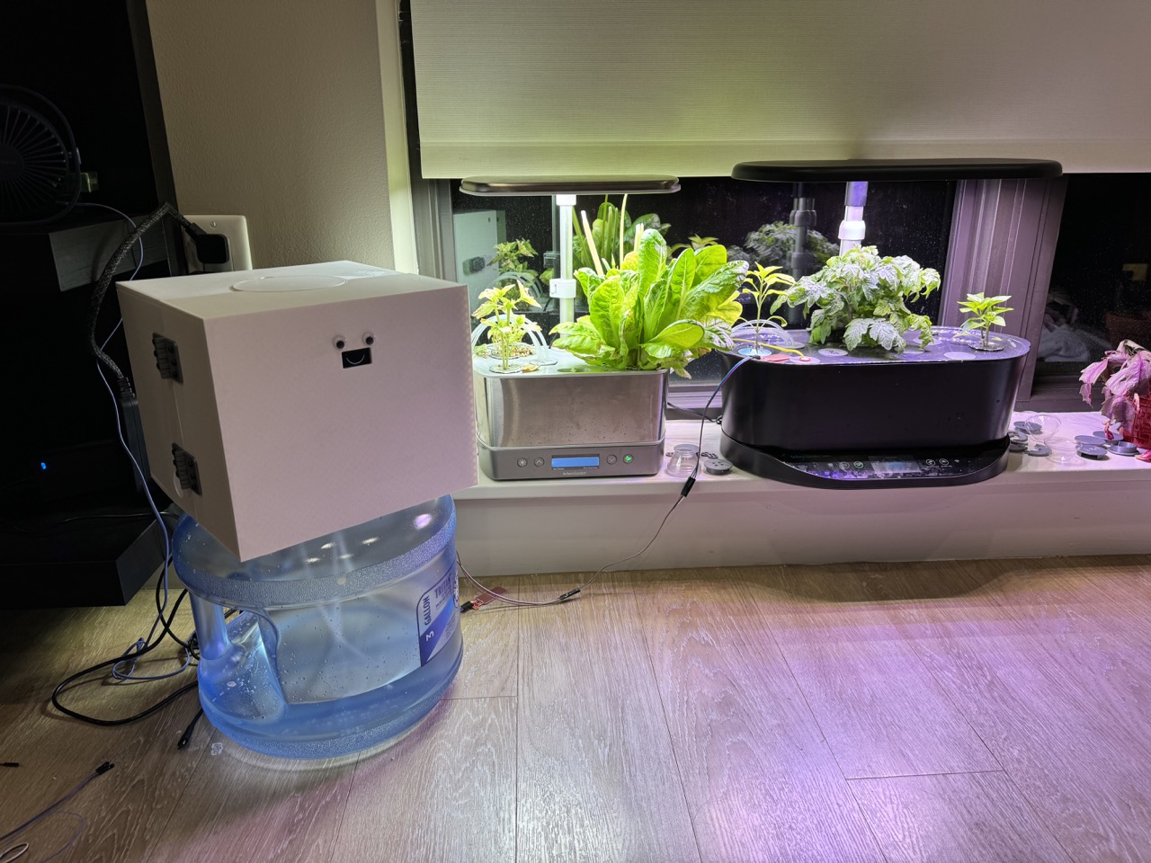
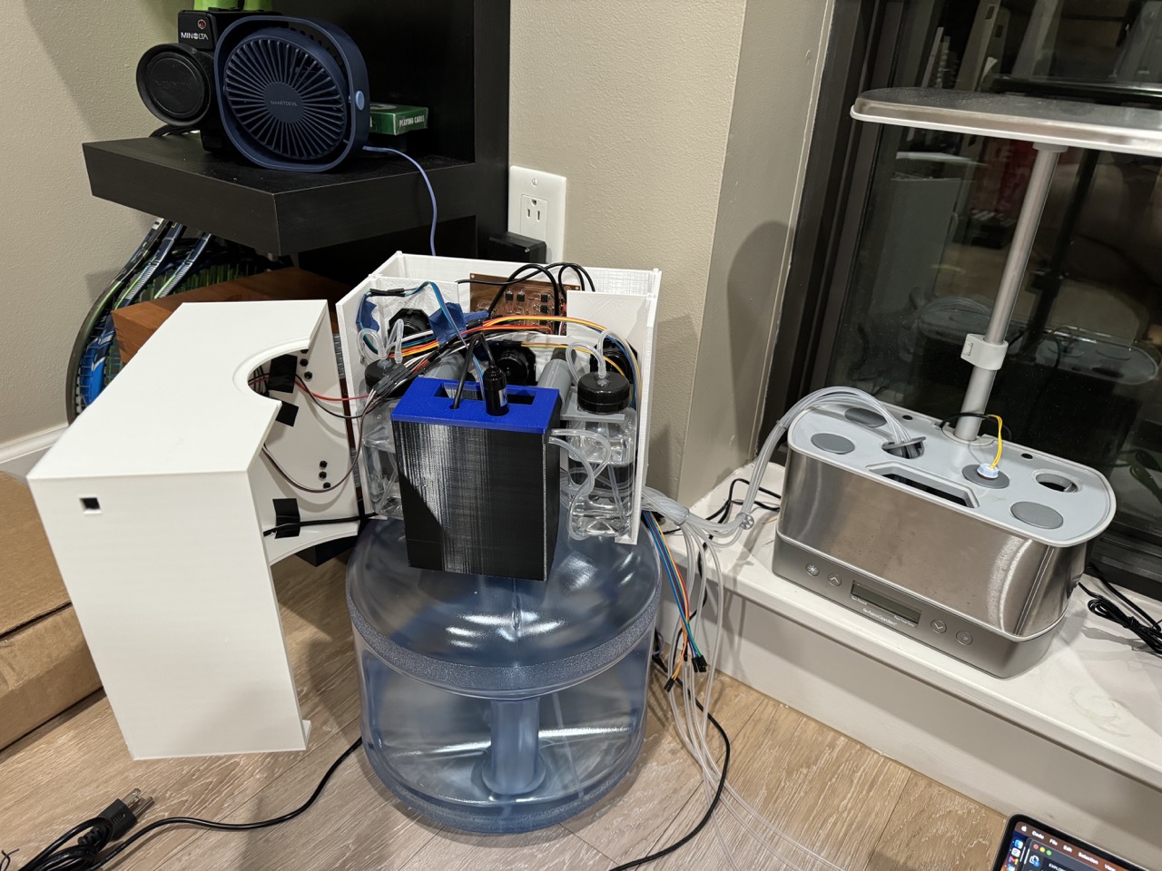
Behold! This collection of pumps, wires, tubes, and 3D Printed plastic automatically waters and feeds two AeroGarden hydroponic gardens.

Hydroponic Watering and Feeding
In my apartment, I have a pair of Aerogarden hydroponic gardens. These offer a convenient package for growing small plants indoors. Plants reside within a reservoir of water that they consume and needs to be topped up daily. Plants are fed nutrients twice a week.

As the plants get larger, they really begin to gulp down water, requiring me to top up their reservoirs (from roughly half full) each day (Note, I gave the gardens a fresh start for the completion of the project). Moreover, every two weeks, the plants require liquid nutrients. This is typically done by pouring a few capfuls into the reservoirs for the AeroGarden nutrients, and then a few eyedroppers full of CalMag. This can be mildly messy and a little smelly. So clearly, I have a massive problem and I must employ maximum effort to solve it. Also, it's generally better for plant growth to always have a full water reservoir, and more notably, to maintain a consistent concentration of nutrients (measured by way of Electrical Conductivity) rather than shocking the plants every two weeks.
Therefore, this project accomplishes the following for two AeroGardens:
- Automatically water
- Autonomously maintain nutrient levels
- Monitor diagnostics such as water temperature and consumption
- Capture images for timelapse creation
Bill of Materials
- 3 Gallon Water Jug
- 9x Peristaltic Pumps
- Raspberry Pi Pico W
- Tubing (I used 4 25' coils)
- 3x Water Level Sensor
- EC Sensor
- Temperature sensor
- 2x Float Sensors
- ESP32S3 Sense Xiao
- MicroSD Card
- Dupont Connector Jumper Wires
- Power Supply(Don't need this much power here)
- 8oz Bottles (for nutrients)
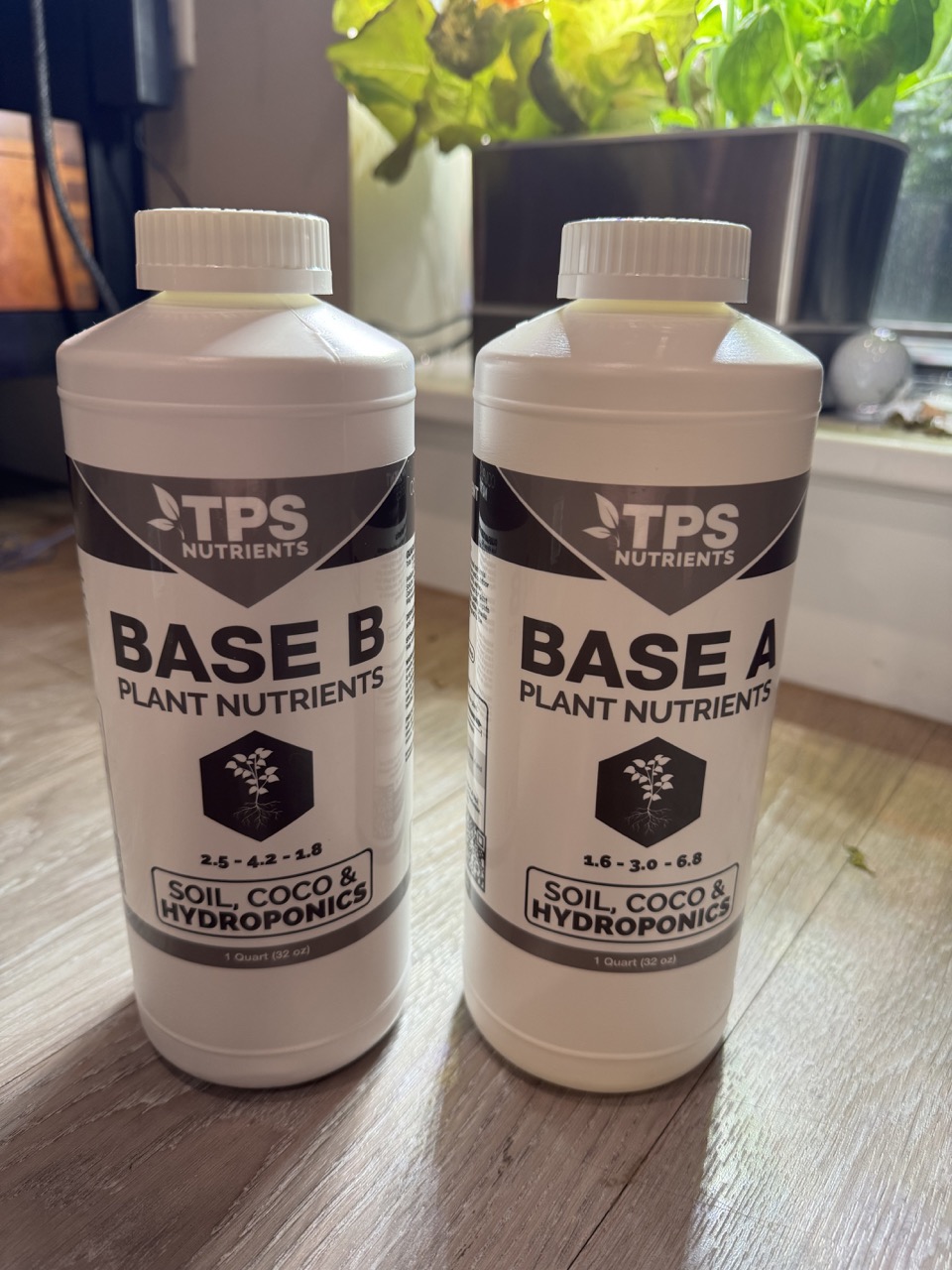
- Plant Nutrients
Code and Files
- MicroPython Code Archive
- Arduino Code Archive
- Juggy STLs
- Pod Cover and Spacers STLs
- Sense Board CAD File
- Control Board CAD File
- Juggy CAD File
Ideation and Brainstorming
Automating hydroponics is not a new idea. In fact, the AeroGarden itself is a semi-automatic approach to the field. I was heavily inspired by Kyle Gabriel's DIY Build Writeup and YouTube Video. While he built an entire setup from scratch, I wanted to make use of my existing AeroGardens and make the build as compact as possible. Moreover, Kyle's setup utilizes a single, nutrient-filled water loop for all of the plants. My approach separates a fresh water supply from the two isolated AeroGarden resevoirs in order to reduce nutrient lockout.
The following notebook drawings show my initial brainstorming of the system's design. While I toyed with the idea of an expandable design, for the sake of simplicity I early on decided to scope down to just two gardens and no pH measurement/correction.
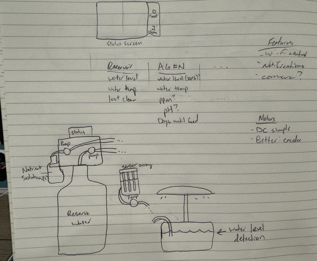

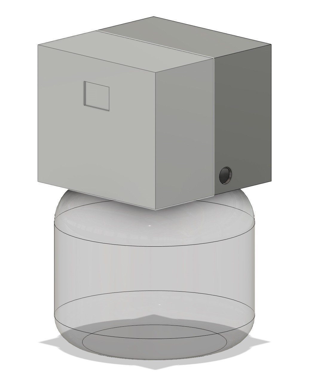
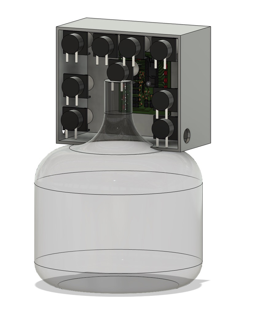
I then began to model it in Fusion 360, taking the shape of a rectangular housing on top of a stubby 3 gallon water jug.
Input Devices
The system utilizes serveral input devices that provide signals to dictate system behavior:
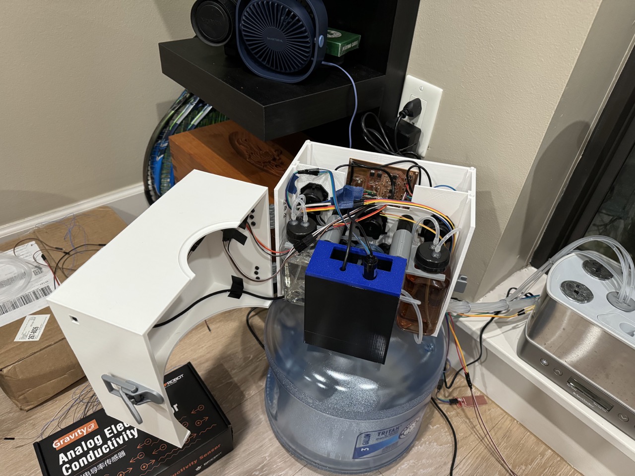
- An Electrical Conductivity (EC) Sensor to measure the concentration of nutrients in the garden resevoirs
- A Temperature Sensor to enable more accurate EC readings
- 2 Float Sensors to determine the water level in the garden resevoirs
- 2 Water Sensors placed around the gardens to act as overflow failsafe sensors
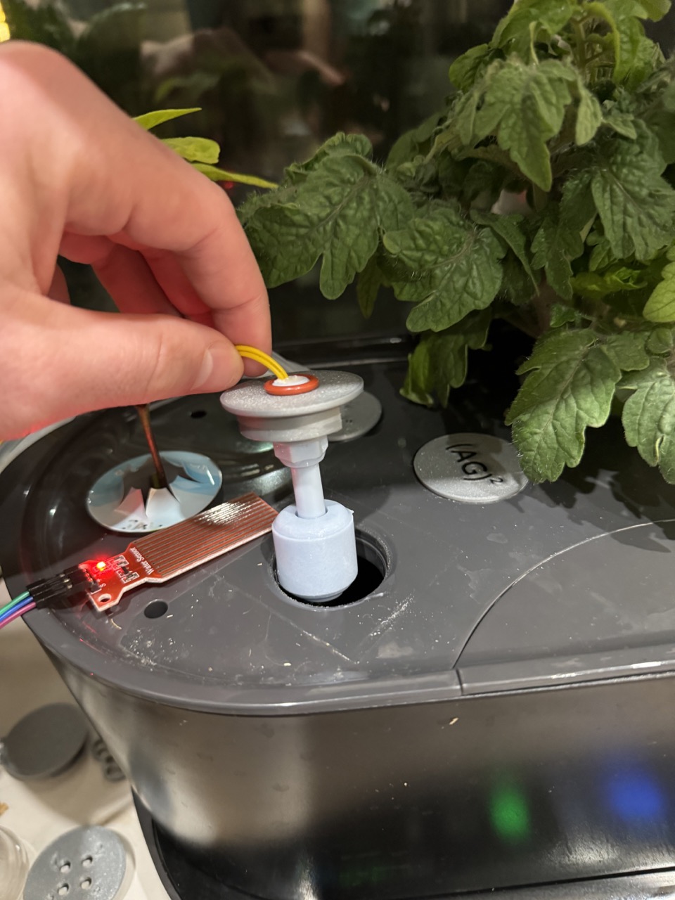
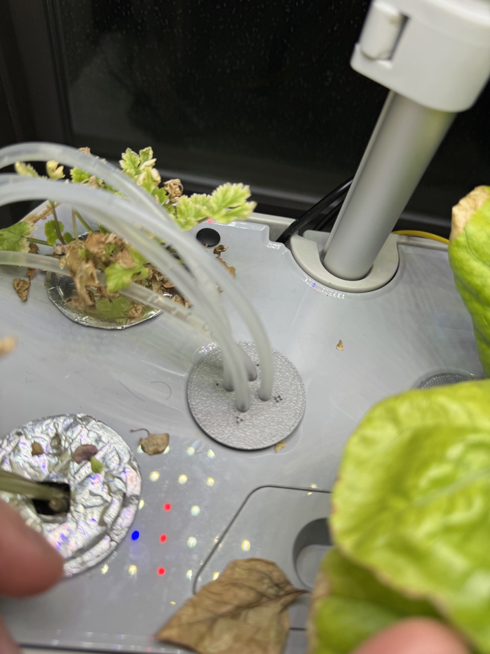
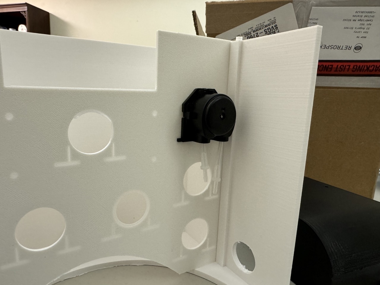
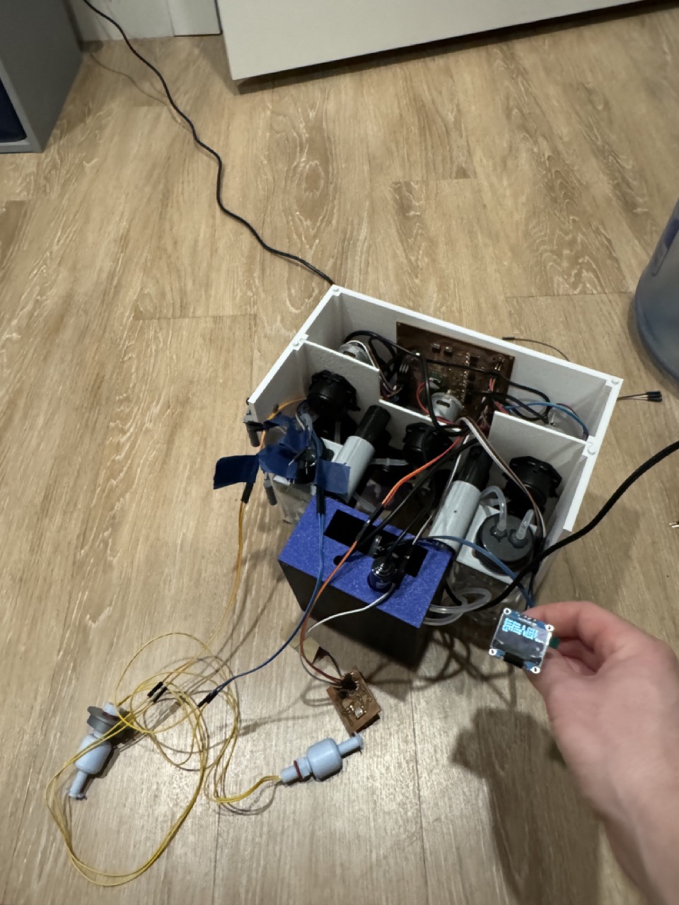
Here you can see one of the float sensors mounted to a pod hole cover. This sends a signal when the floater rises, lining up with the AeroGarden's water fill line. Moreover, it is next to an overflow sensor that detects the presence of water should the garden overflow. There is an additional overflow sensor placed below the gardens.
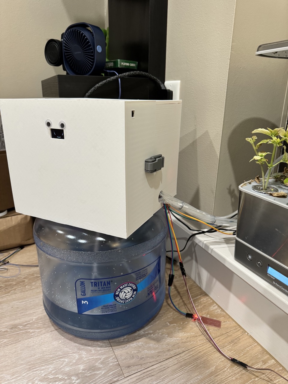
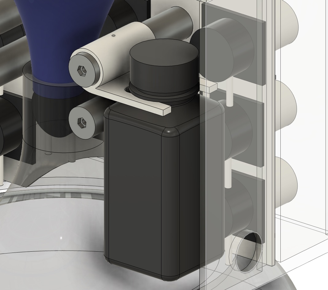
Mounted to the front, you can see the black & blue printed test bath with the EC and temperature sensors poking through the top, where reservoir water will be tested for nutrient concentration (more on this later). Finally, the wires for the remaining input devices are routed out the right side of the device.
Input Device Code
I wrote the following code to enable the use of my sensors. ChatGPT helped with a lot of the boilerplate here.
- sensors.py - groups all of the sensors into a central location for testing
- water_level_analog.py - Reads analog voltage from the water level sensor
- ecsensor.py - Calibration and readings, rewritten library to support python3 and OOP
- ds18b20.py - Mini library that supports temperature readings and OOP
I developed and tested the bulk of this code in week 9 using the simple RP2040 board I made in week 6.
Output Devices
In order to deliver water and nutrients and route reservoir water for EC testing, I need to operate several liquid pumps.
Four pumps used for each garden (2x4 = 8 pumps):
- One Pump from water jug -> garden reservoir
- One Pump from nutrient solution A -> garden reservoir
- One Pump from nutrient solution B -> garden reservoir
- One Pump to/from sensor testing bath <-> garden reservoir
As well as one additional pump from water jug -> sensor testing bath in order to wash the probes
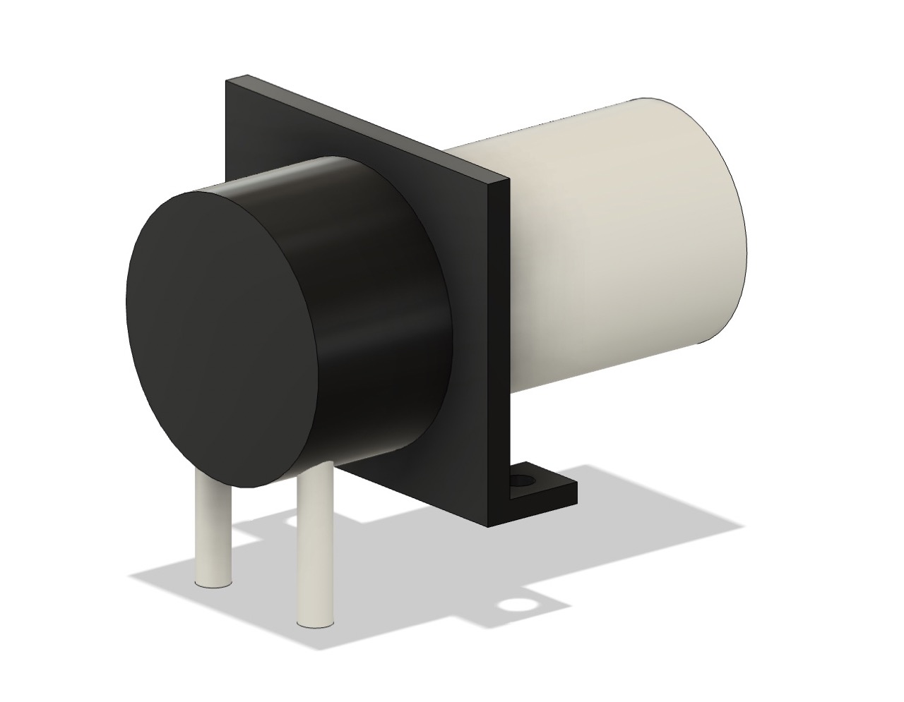
Therefore, I need a total of 9 pumps. I am using these brushed 12V DC peristaltic pumps. I opted for peristaltic pumps because they do not actually interact with the liquid, instead physically compressing the tube.

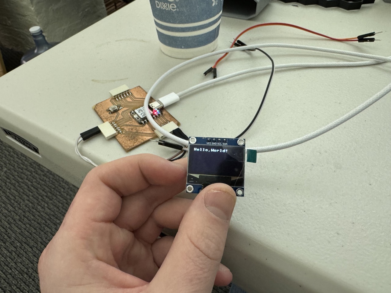
Moreover, I want to make use of a mini I2C OLED screen to print status messages.
Output Device Code
I wrote a simple library to make interacting with my pumps easier:
- pumps.py - contains the
Pump()and BiDirectionalPump() classes with methodson()and off() - screen_test.py - Tests the I2C OLED screen
- ssd1306.py - Driver for the screen (source)
Making the Brain
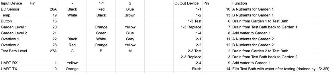
In Week 10 I set out to make a single board to handle most of the project's function. Because the system requires 6 input devices in addition to 9 pumps, a screen, and a serial interface (more on those later), I opted for the Raspberry Pi Pico W microcontroller. Its array of GPIO pins and support for MicroPython made it a clear choice. Moreover, it uses an RP2040 MCU, which I used in previous weeks in the XIAO form factor. Ahead of time, I charted out what devices I needed and what pins they would connect to. I made sure to future-proof the board by adding extra input and output circuits should plans change.

The pumps are rated to run at 12V, but the Pico's pins can only produce 3.3V (and not much current either). Therefore, we need an external 12V power source and to toggle power to the motor with the logic voltage (3.3V) from the Pico. This can be done with an N-channel MOSFET. The following is the circuit I used to control the unidirectional pumps. It is duplicated twice over to utilize the 2x2 pin header. This circuit controls two unidirectional pumps.
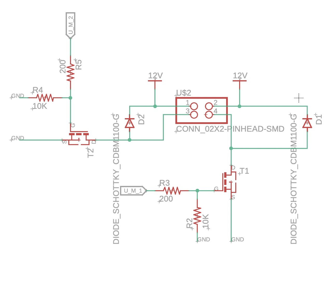
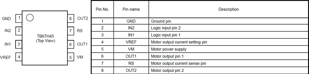
Moreover, I utilized the TB67H451AFNG H-bridge in order to drive the two bidirectional pumps. This allows one pin to trigger the motor in the forward direction, and another to trigger the backward direction.
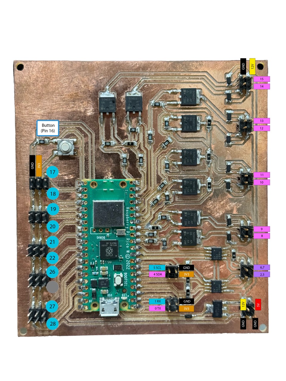
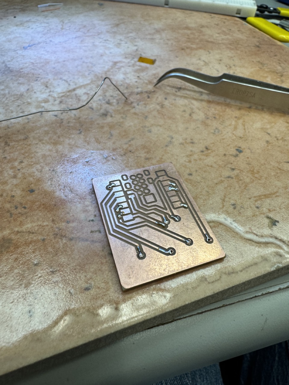
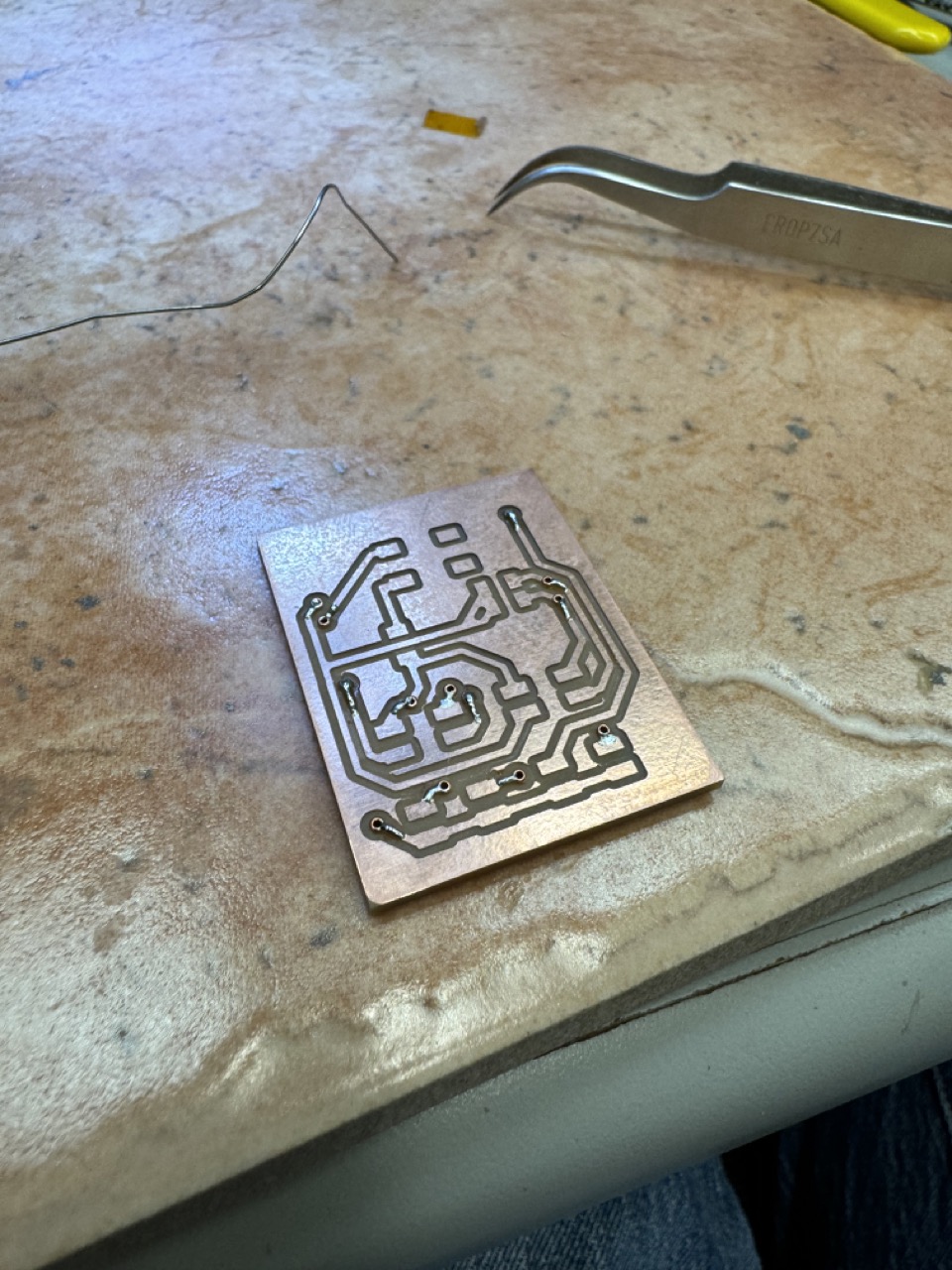
Here is the routed board design (note, there are a few changes from the initial design in week 10 that are annotated at the end of this section)
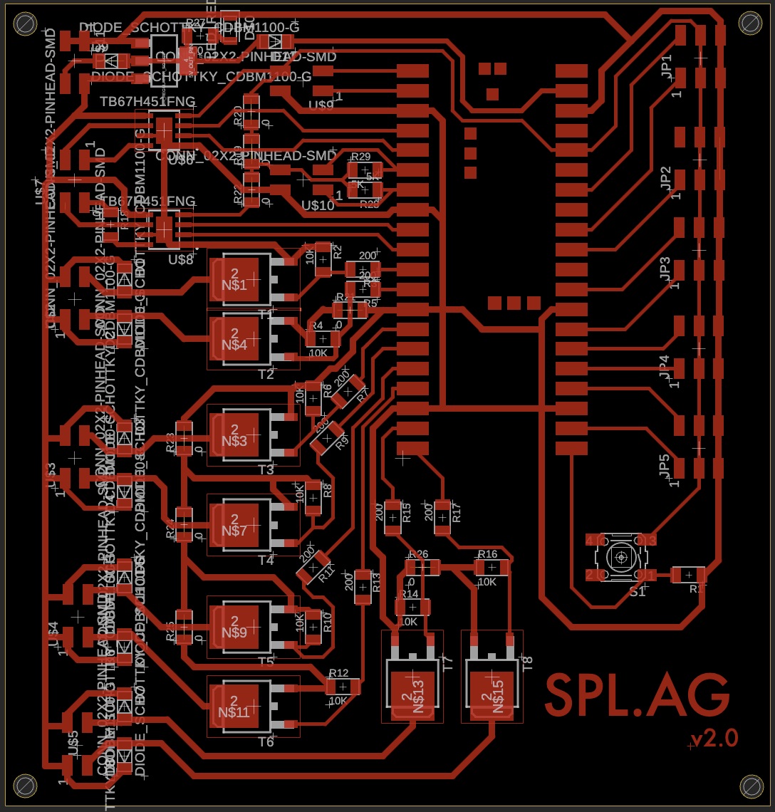
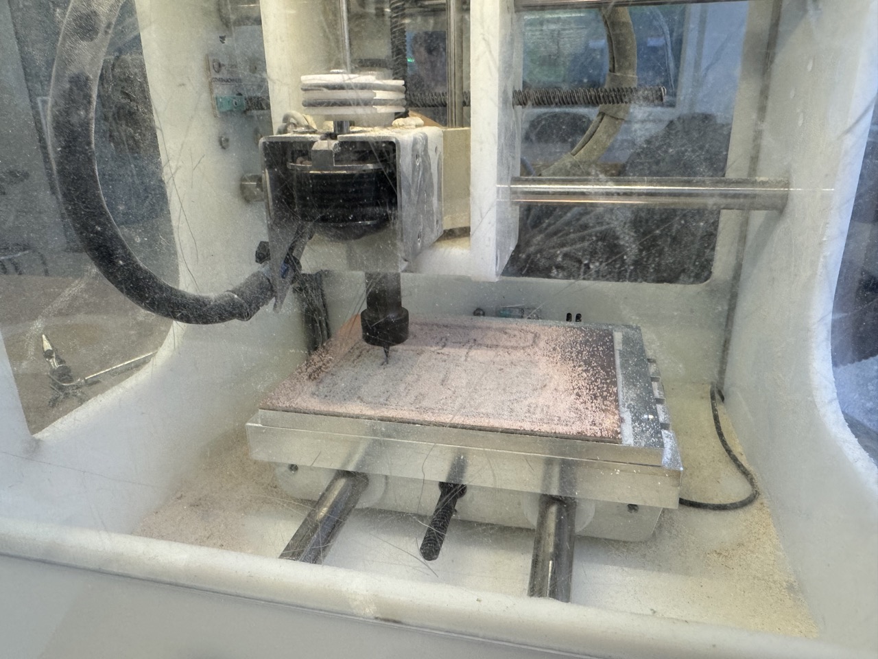
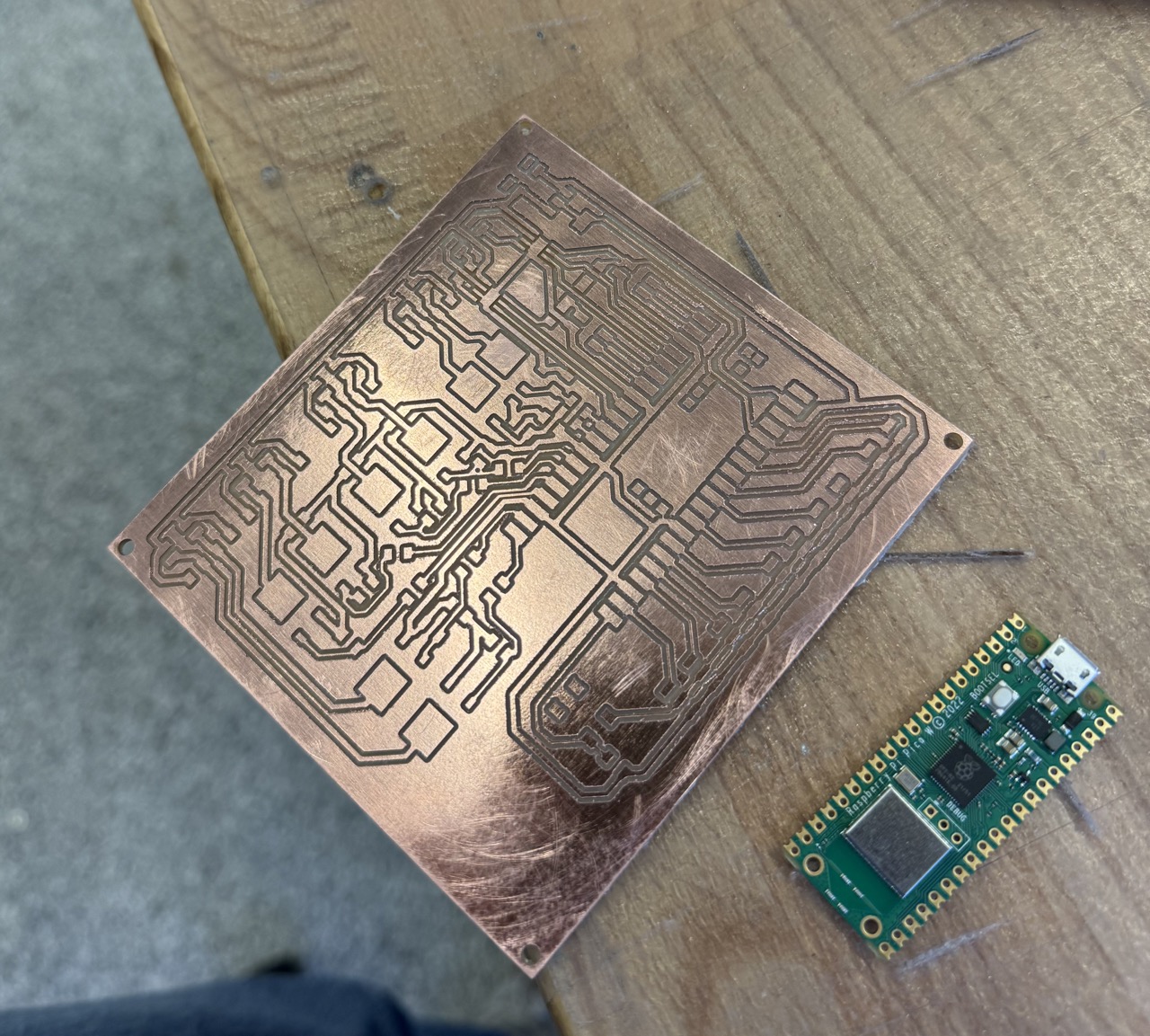
I then milled the board on the Othermill.
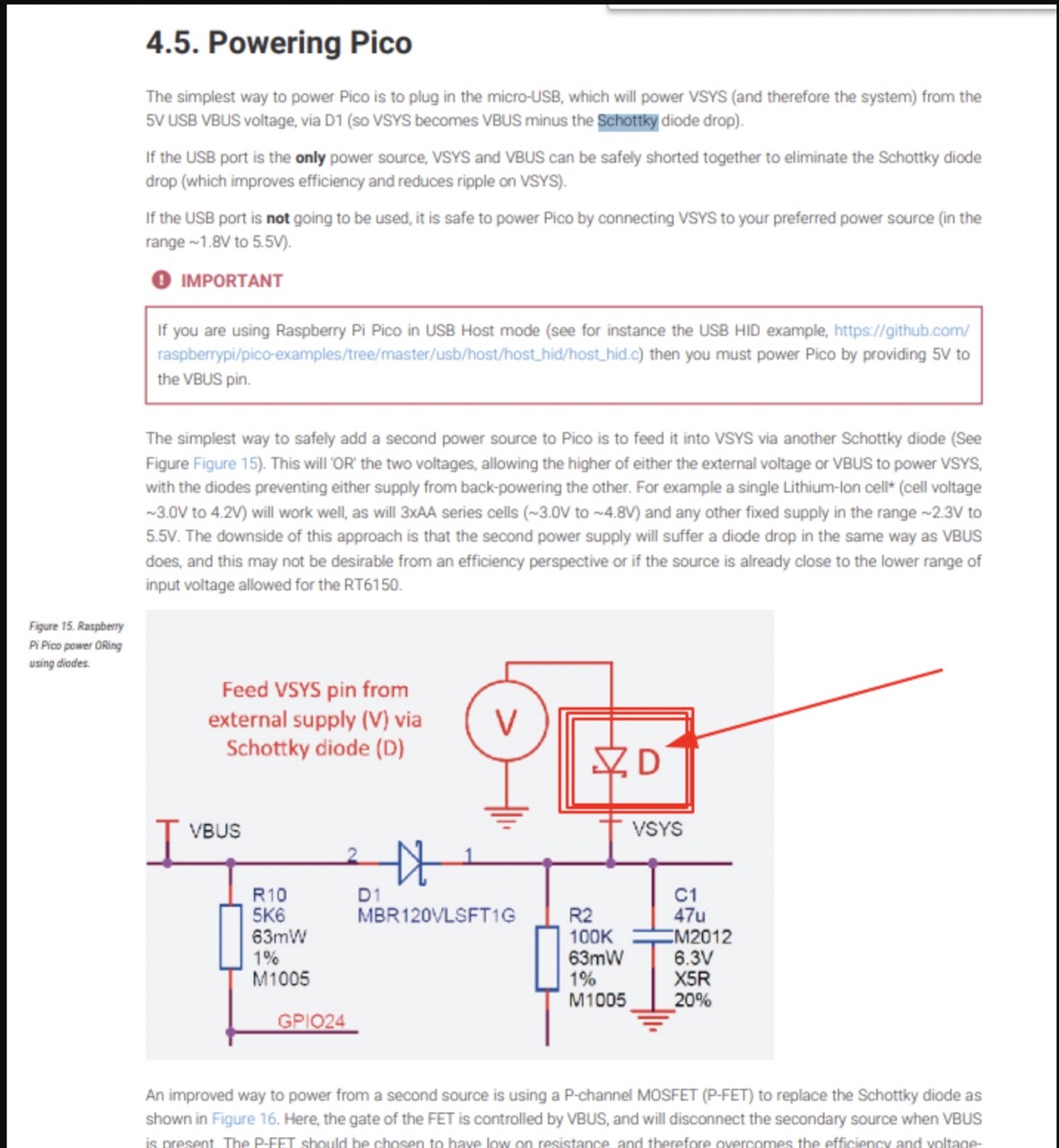
Additionally, I made a few edits from the board as I assembled it in week 10. Firstly, I added a diode (which allows current to flow only in one direction) between the 12V->5V voltage regulator and the Pico. This ensures that if the pico is connected to power on both VBUS and VSYS (USB and our power supply), current will not travel up into our voltage regulator and power supply from USB. This allows us to power the pico and pumps from the power supply while still being connected over USB to upload code and read logging output. The relevant entry from the Pico's datasheet:
Moreover, I created a 5V out and GND pin pair to power another board. More on that next. This has a diode as well for the same reason mentioned above.
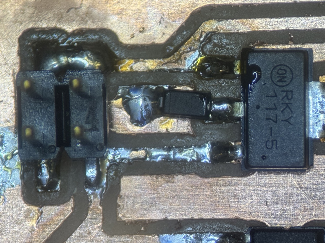
Finally, I added an LED to indicate when the board is powered by the external power source. While I jerry-rigged each of these changes, I have integrated them to the fusion files should anyone reading want to make one for themselves. The final board:

Sense Board
While the aforementioned board controls most of the device's function, I want another board with the following features:
- A camera to take a timelapse of plant growth (and optionally a live feed)
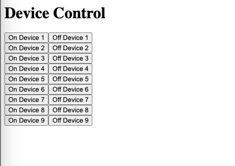
- A web server to interact with the system, check data, and test components
Given these requirements, the Seeed Studio Xiao ESP32S3 Sense is a great fit given the built-in Wi-Fi, camera module, and SD Card slot. This board is connected to the Pico controller board over serial inside the project housing, so that controls from the web portal can be sent to the pumps.
I initally planned for this board to drive the OLED screen, but I could not get it to pick it up over I2C. I am unsure if I did not set up the pull down resistors correctly or if I fried the board partially when I soldered it via reflow. Moreover, I planned to connect an array of buttons placed on the front panel of the device to the board, but I decided I didn't really need buttons and preferred a cleaner external appearance.
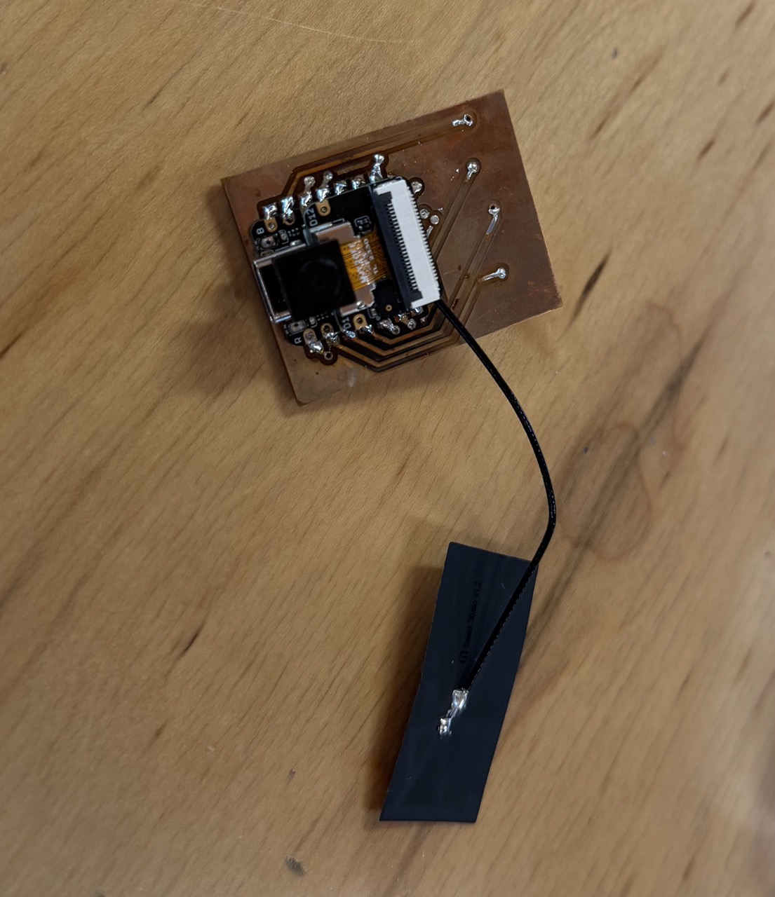
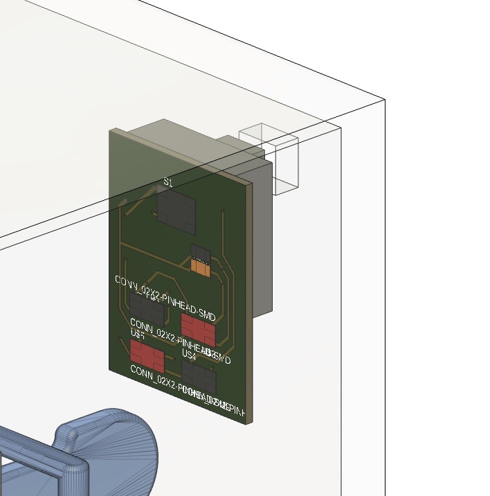
I describe the creation and testing of this board more fully in Week 11. In order to reduce footprint and allow I/O to be routed behind the chip, it is a double-sided board.
This board is powered from the main control board pins I jerry rigged in the previous section. Here is the completed board. Note the camera, SD card, and antenna built in, while the I/O pins are on the underside of the board.
Device Design
Now with the sensors, pumps, and control mechanisms sorted, it was time to design the housing to bring them all together in a neat package.
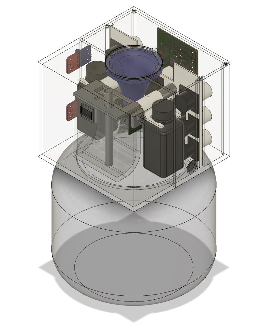
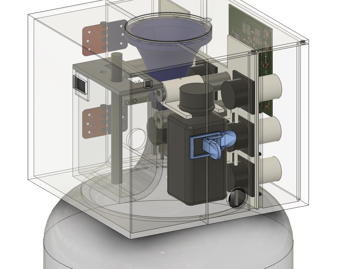
The housing contains the following:
- 9 Peristaltic Pumps
- 2 Nutrient Bottles (Solution A and B)
- Testing Bath to measure garden EC levels with probes
- Control Board (Pico W)
- Sense Board (ESP32S3)
- OLED Screen
- Funnel to easily refill the jug
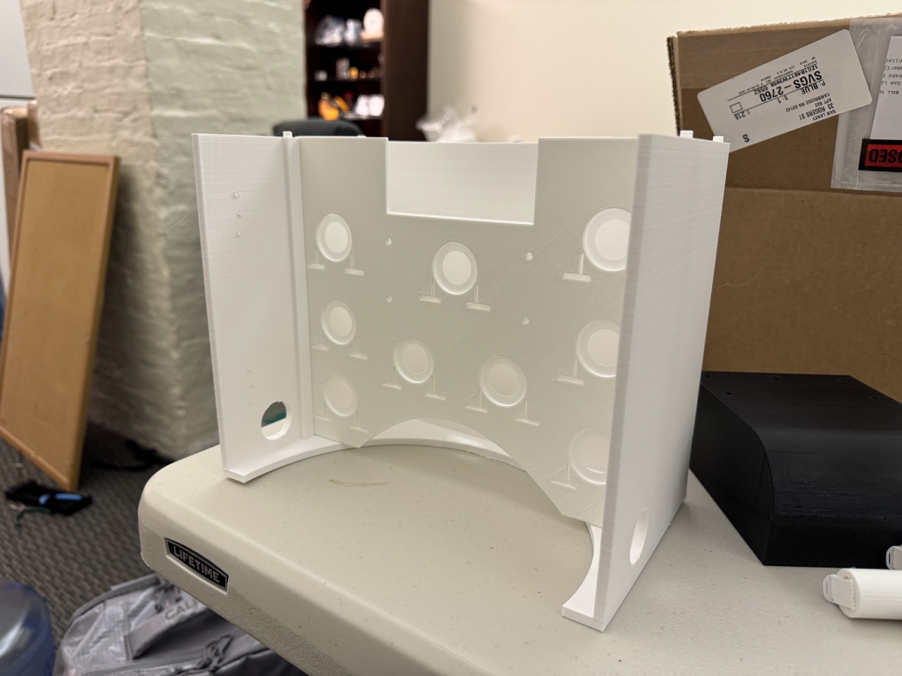
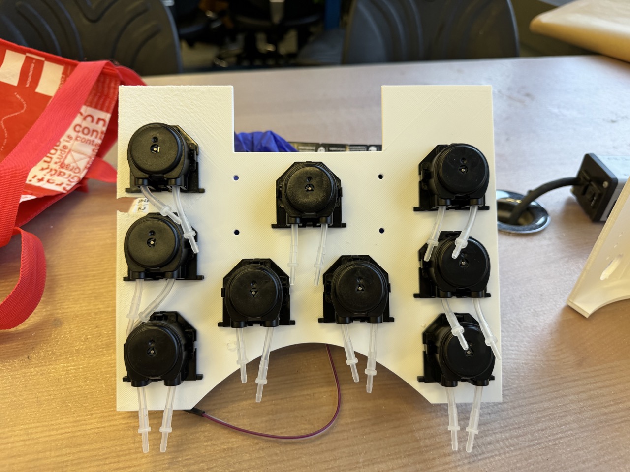
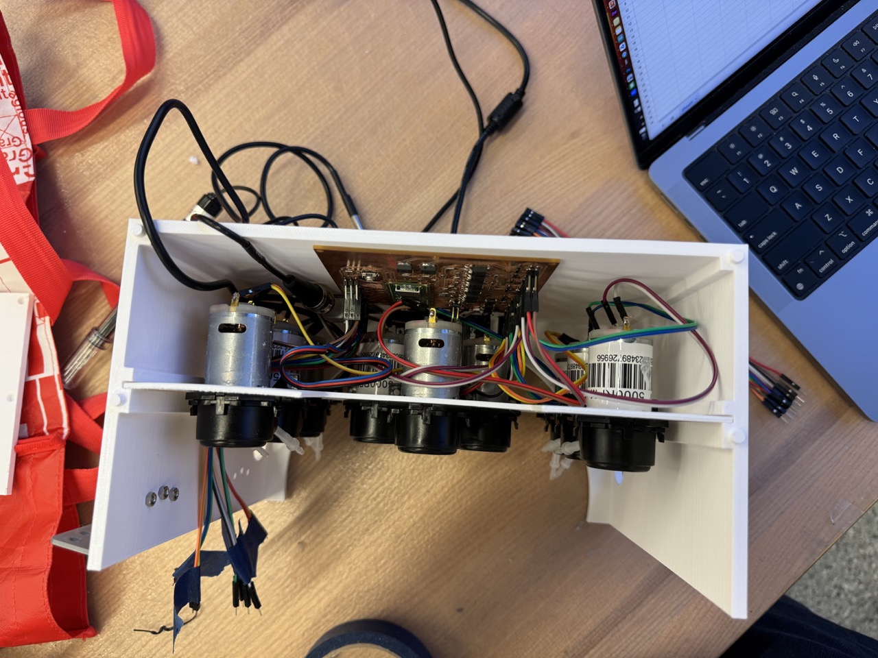
The main driver of the design dimensions was the sheer number of pumps. I decided to mount them to a 3D printed plate that could slide in and out of the back housing via a set of vertical rails.

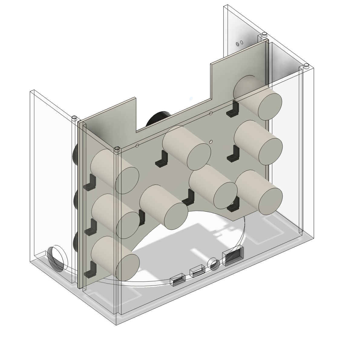
Next, we need a place to put the testing bath, where water from the gardens will be pumped in to test for nutrient concentration. I use the following pillars to mount the bath and provide room for the opening of the jug. Openings on each end of the pillars allow for a nut to be glued in for mounting.
The testing bath is shaped such that it is deep enough to fit the EC probe and clear the jug via its curved bottom section.
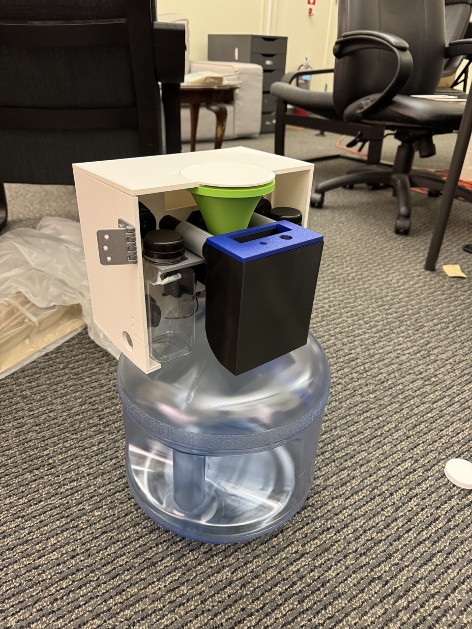
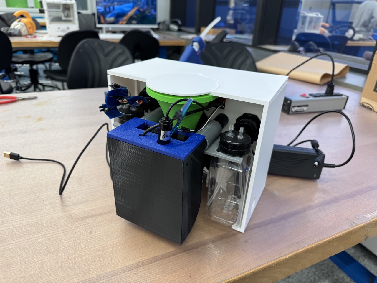
This is starting to get pretty complicated, even without the tubing and wiring that will be present in the real version. Therefore, I want an easy way to refill the water jug without removing the device with tubes sprawling. A funnel mounted to the top of the box allows for easy refill and leaves room for tubes to go into the jug. This top piece friction fits into 4 pegs to allow for easy removal and access to the internals.

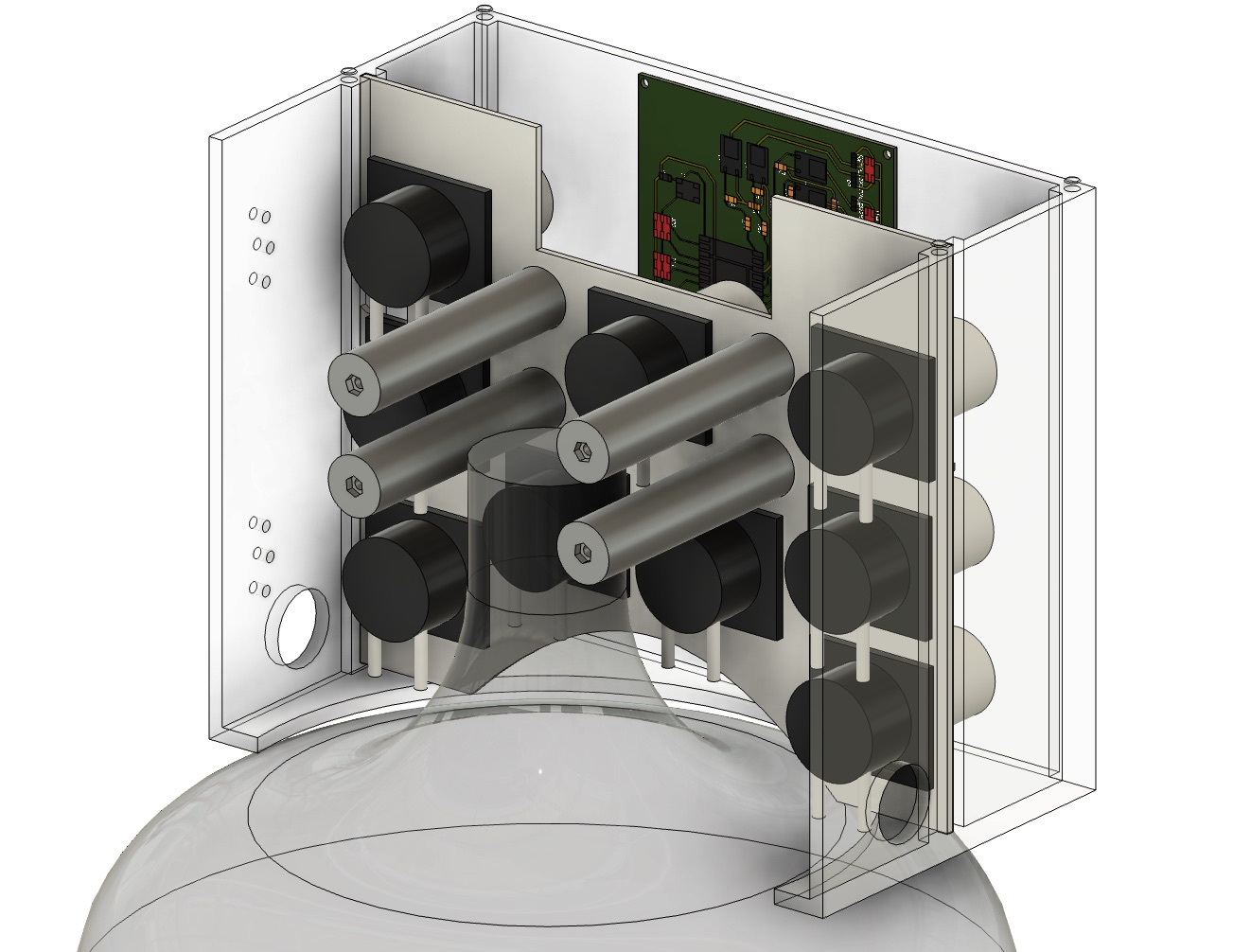
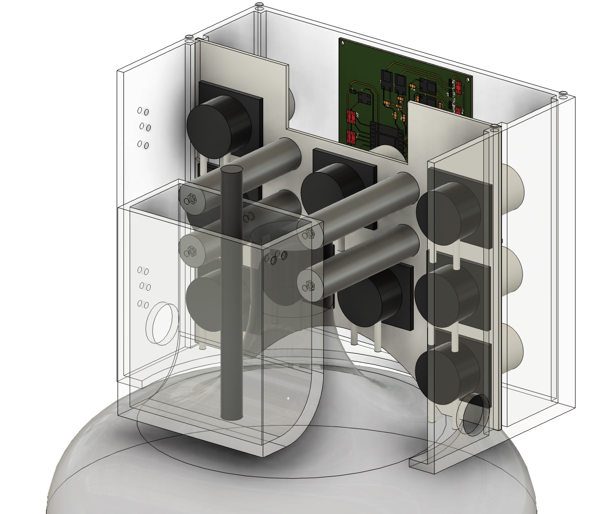
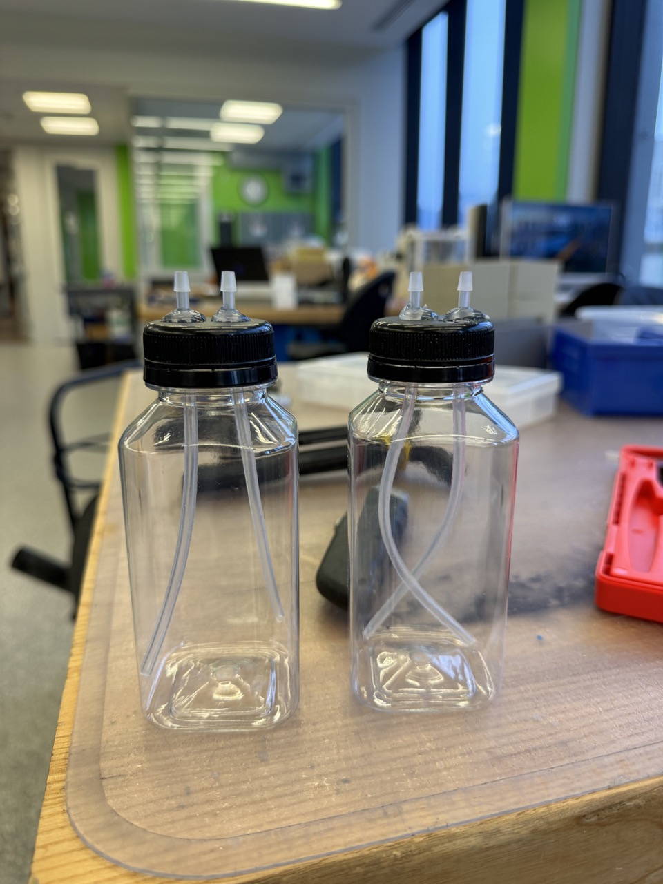
Moreover, we need a place to store our nutrients. I make use of two 8oz bottles held by mounts connected to the top row of pillars.
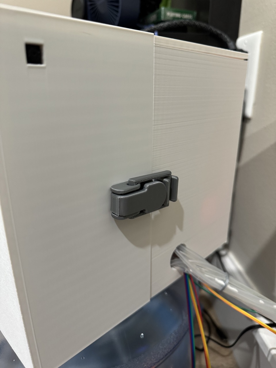
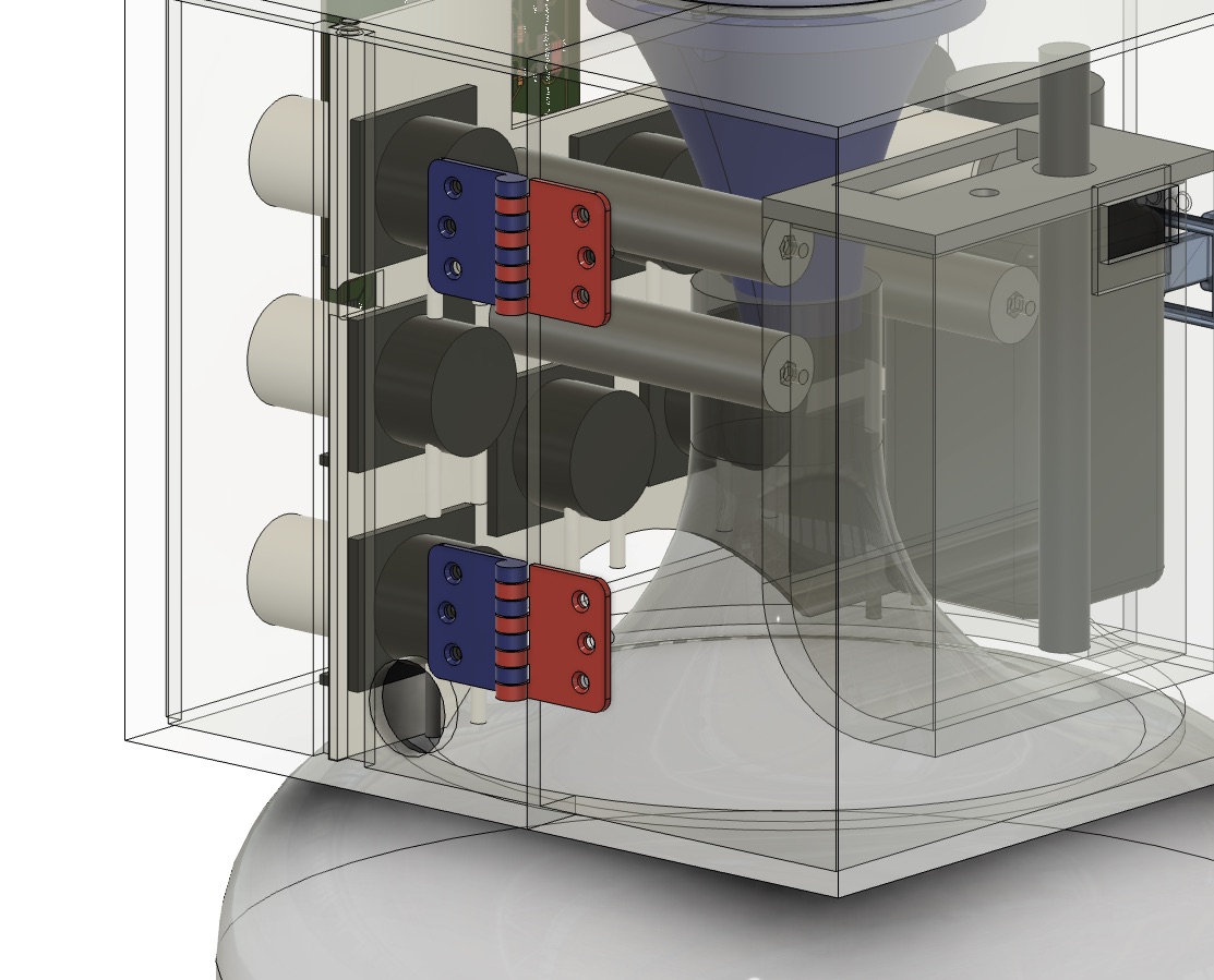
The front half of the enclosure only has the screen and the sense board mounted to it. This allows it to swing open easily for access to the internal components. I made use of this print-in-place hinge and this print-in-place latch to bring the pieces together.
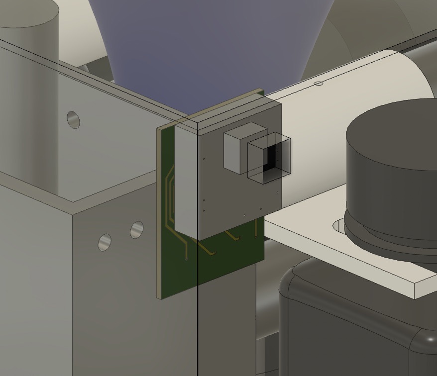
Finally, the Sense board is mounted to the inside of the enclosure, allowing for the camera to peek through, while the pins can be accessed from behind.
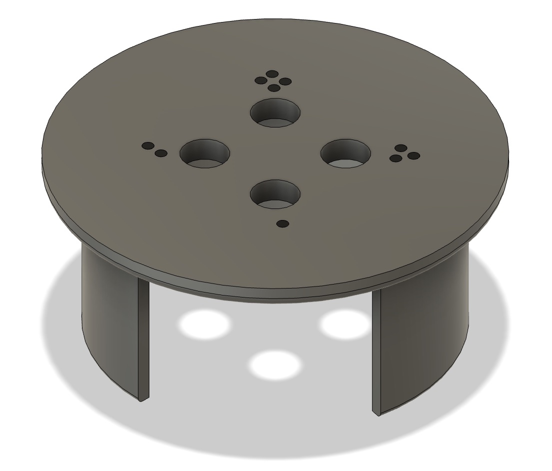
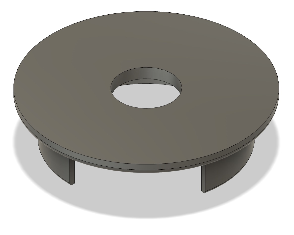
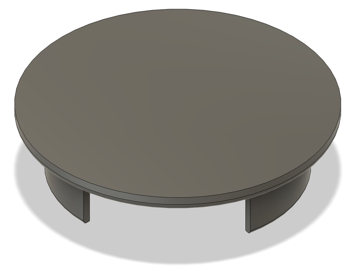
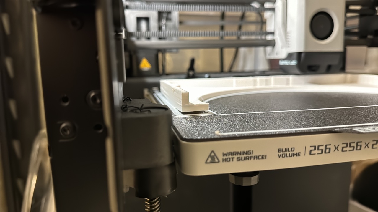
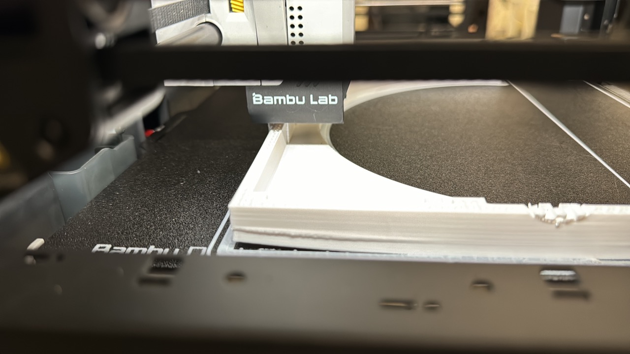
In order to interface with the gardens, I make use of extra pod holes on the AeroGardens (it is not recommended to make use of all of the pods to avoid overcrowding, especially when growing larger plants). The four hole pod cover allows for 4 tubes to pass through into the reservoir. Each hole is labeled for convenience. The large hole cover is for mounting a float sensor. The plain cover is used simply to cover up any unused pods to prevent the water reservoir from being exposed to the grow lights (algae). Finally, I made a decorative cover to be printed on a Bambu Lab printer with AMS. (Adapted from this design)

Finally, I designed a pair of spacers to help sort out my tubing. I utilize the notch to indicate which tube is first, then spiraling in order afterward.


Printing and Assembly
Now for the fun part. To print this array of parts, Sungi was gracious enough to let me use his print farm of Bambu printers to parallelize the process. Also, they are super fast, so it made it easy to rapidly prototype when a part didn't come out how I intended. Most parts are PLA and were sliced with the Bambu slicer. STL's are linked in the files section at the top.
I had a few issues with curling on the larger prints, but it didn't seem to affect things too much in the end.
I was most nervous about the plate. How would I mount the pumps? Would it be sturdy enough to support the pumps? would it fit nicely into the rails?
Thankfully, the answer was yes to both. I really didn't have a plan for mounting the pumps. They had an odd mounting bracket with a small hole, but it was awkward with the plate in the way. Thankfully, they friction fit just fine!

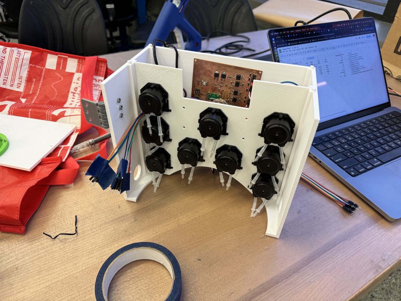
With all of the pumps mounted (much heavier than I anticipated):
Next, I continued assembling, ensuring parts fit together and making changes (either new prints or jerry-rigs) where necessary).

As I added the bottles, I realized I could only access them by fully removing the pump plate. If I were to design a version 2, I might change this, but it wasn't a dealbreaker.

Moreover, everything fits on the jug well, and the lid/funnel combo work as desired.
Next, I added tubes to the nutrient bottles. I drilled two holes in each of the lids, fed tubing barbs through, then hot glued them in place.
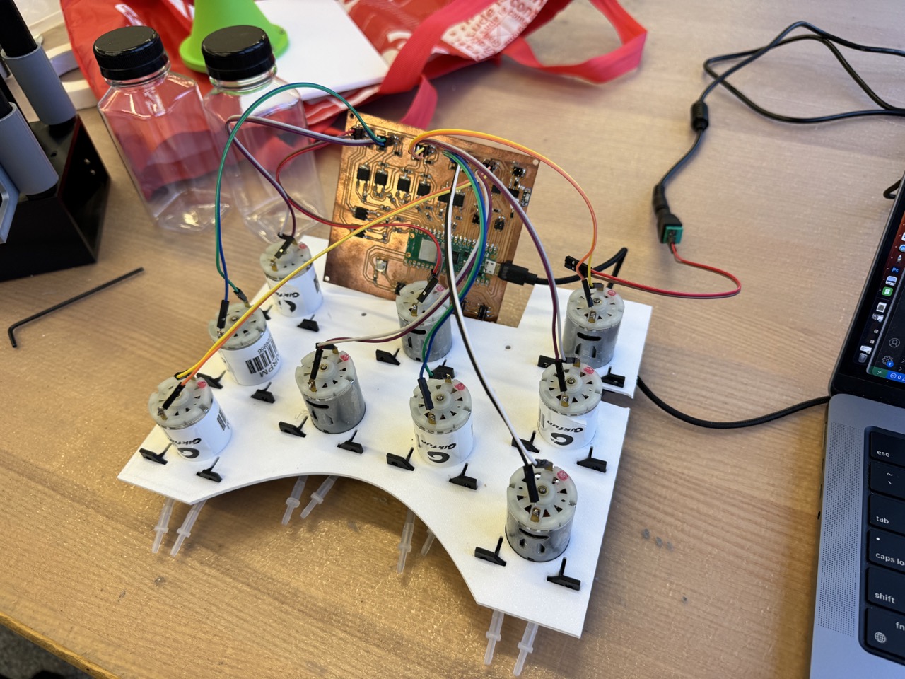
Next it was time to wire up each of the pumps. Out of laziness I just used dupont jumpers so it would be easy to plug them into the control board. Looking back I should have heat-shrunk the connections.
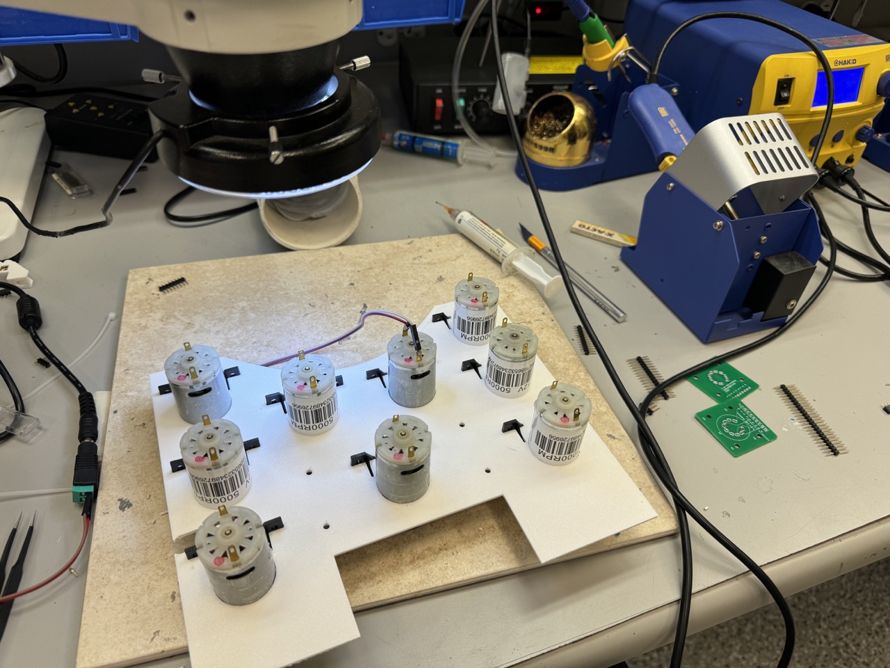
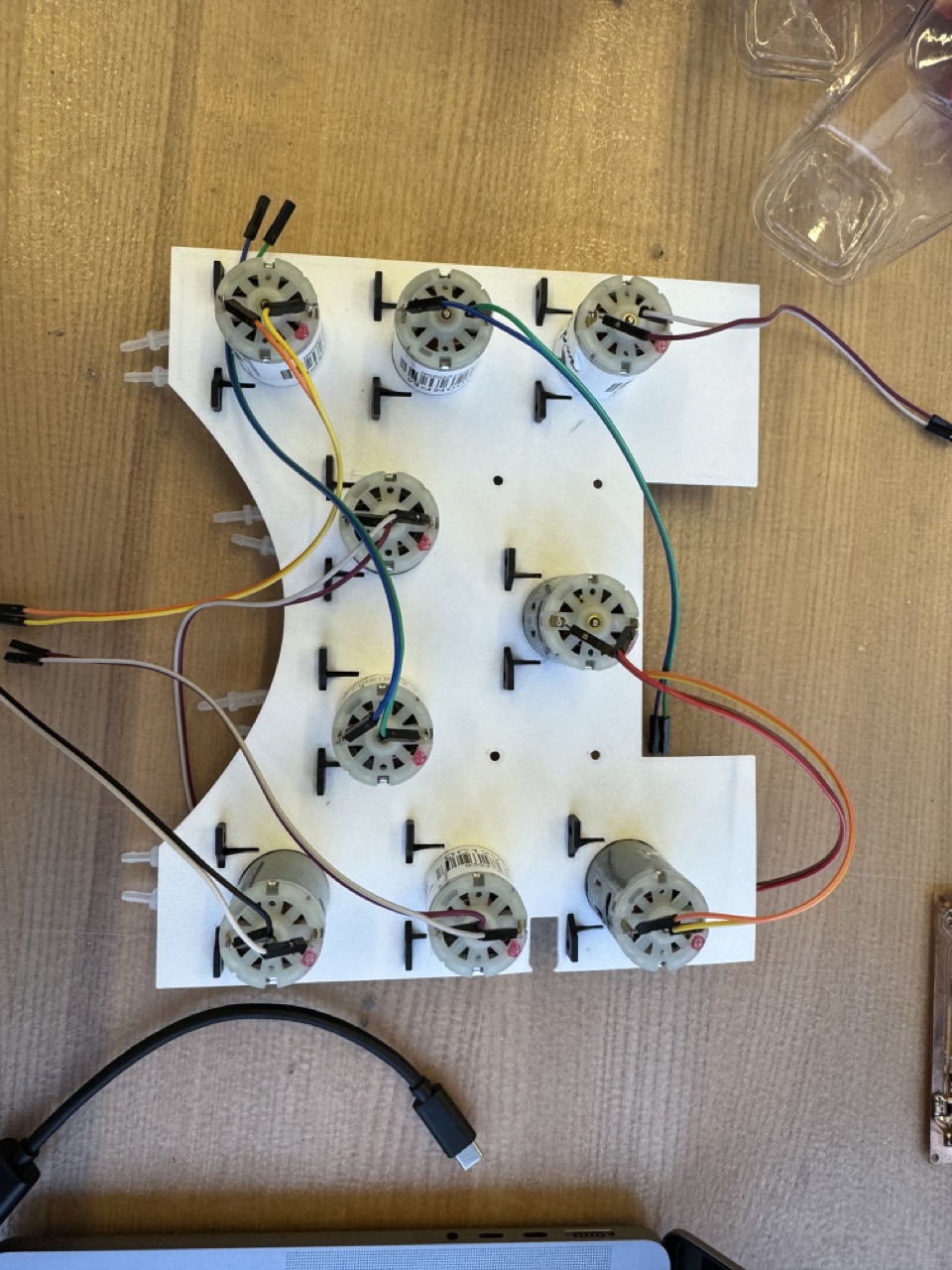
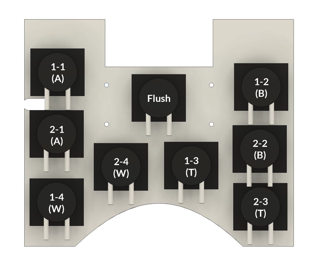
Then I wired them up to their correct pins as I had assigned them and based on this diagram (it wasn't until I made this diagram that I realized how asymmetrical the pumps were, oops).
Things were starting to come together!

Now that I had wired up each of the pumps, I wired up my input devices, again based on how I had previously assigned them in the spreadsheet. To reduce clutter, as many of the inputs would be outside the enclosure, I routed stubs and labeled them for future assembly.
I did not leave myself a lot of room back here for wiring!
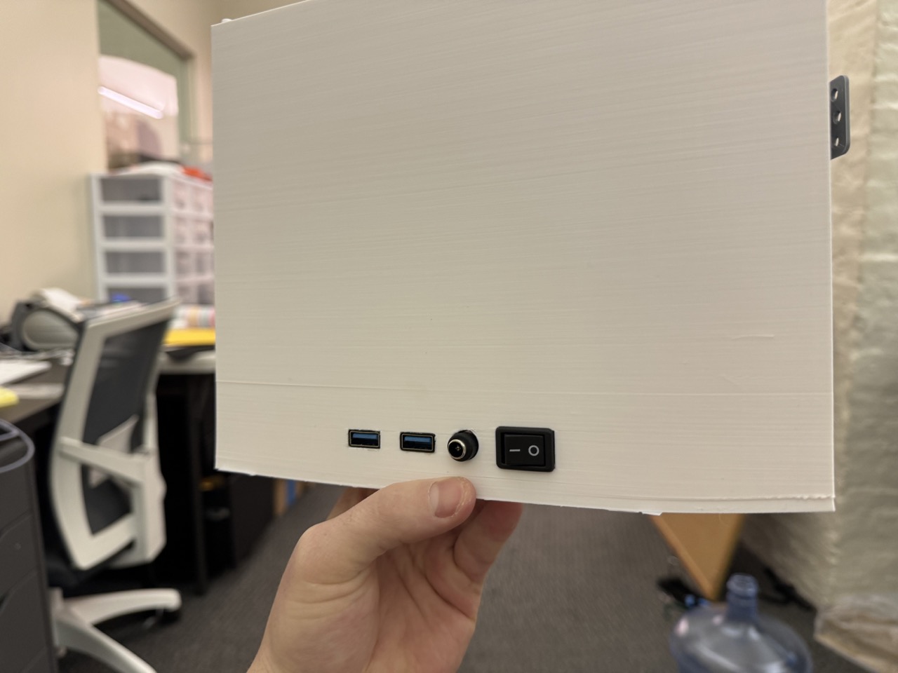
I also added a power switch. This is one of the best decisions I made as this made it very easy to turn the system on and off without dealing with the wall plug. I also attempted to add these female-female USB connectors that would be plugged into the boards internally, making it easy to plug my laptop into the back and reprogram them. However, they didn't work and I got a lesson on the USB standard - this now requires a male-male, which is a no-no. It also breaks the USB-C connection protocol. Instead I just have cables to the boards tucked behind in case I need to plug in (note: I used a slim, right angle USB-C connector for the Sense board)

Next, I began wiring up sensors and testing! I actually ran into dozens of issues during this phase, but it mostly came down to bugs in my code, not understanding how MicroPython works, and stubbornness. Also, don't accidentally flip the polarity on the OLED. It fries the screen... Finally, however, I got the float sensors, water sensors, screen, and serial communication working.
I then mounted the front panel, the OLED screen, and the Sense Board.

After a connection failed that I could not reach, I realized that the entire mass was mounted to the pump plate, and it is HEAVY. Was that a great design decision? I don't know, but other than being inconvenient it hasn't failed (yet).

I then got all of the tubes routed. I had to remove the test bath to reach all of the pumps.
Finally, I was testing with the pumps and a garden!
As I was testing the nutrient pumps (with water in the bottles), I realized I was trying to pump liquid out of a sealed container, which is a problem. I made a tiny hole in the lid with a bottle to allow air to in to replace the liquid that is pumped out.

Here is the final rat's nest of wires...

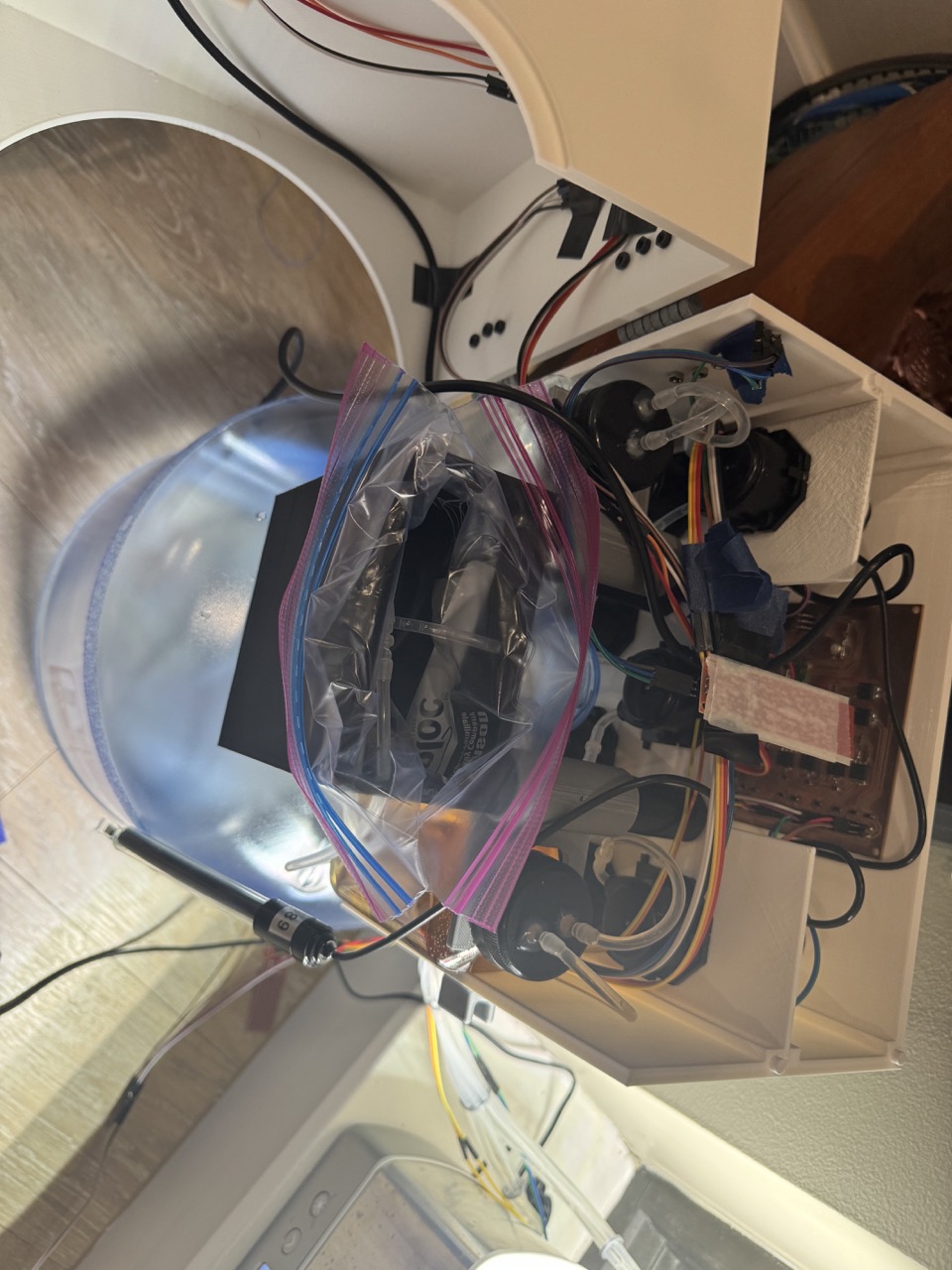
After I added the nutrients and continued testing, the test bath began to leak. I had read that FDM 3D printed parts should not be used for watertight applications, but I hoped that by increasing the wall thickness I would be fine. I was wrong. So I added a ziploc bag to the testing bath to hold the liquid. In the future I will pursue resin printing a test bath.
Concept of Operations
Juggy's function is outlined in main.py. How it works is summarized as follows:
System Setup
Juggy initializes with a setup of logs, hardware components (LEDs, OLED screen, sensors, and pumps), and UART for serial communications, readying the system for real-time environmental management.
Main Operational Loop
The core functionality resides in a perpetual loop, executing the following tasks:
- Sensor Monitoring and Commands: Checks water levels and overflows while listening for UART commands to adjust operations or run diagnostics.
- Overflow Prevention: Disables pumps during overflow conditions to mitigate water damage, logging the events as critical.
- Water Level Management: Maintains optimal water levels through automated refills, ensuring consistent plant hydration.
- Nutrient and EC Adjustment: Periodically measures EC levels to adjust nutrient concentrations, promoting healthy plant growth.
- Daily Summaries: Compiles usage summaries and adjusts nutrient baselines as necessary, aiding in growth tracking and planning.
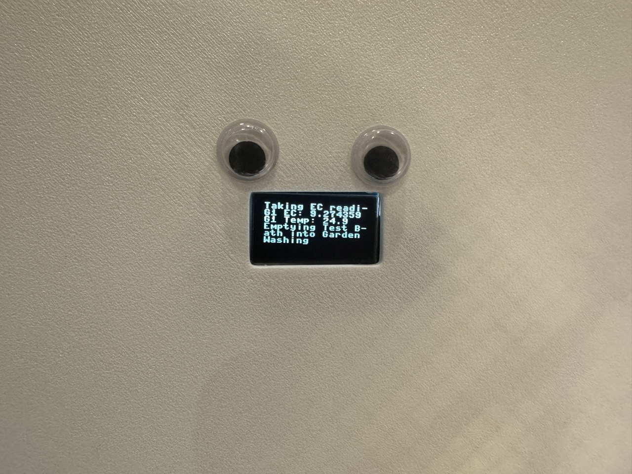
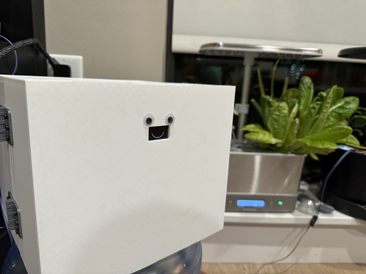
- Efficiency: Enters sleep mode with a smile, waking each hour to check garden conditions.
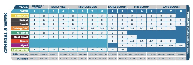
As time passes, the target EC level shifts, based on the following chart:
Conclusion
In wrapping up this project, I'm proud of what I've created. When I started this class, I told myself that I wanted the final project to be something I cared about and would actually use, not something thrown together. Despite the hurdles, from leaky test baths to a labyrinth of wires, (AG)^2 stands as a personal victory and a playful reminder of the joy found in creating solutions that, while they may not streamline life, enrich the experience of learning and making. It's not just about saving a minute a day; it's about the hours spent troubleshooting, coding, and assembling—a unique blend of frustration and fulfillment. I will continue to improve the project as time goes on, and I will be sure to log them here, along with a timelapse. As I look at the glowing LEDs and listen to the hum of pumps, I can't help but smile at the thought that maybe, just maybe, I've made my plants a little happier. And in the end, isn't that what it's all about? Here's to solving small problems with maximum effort and to the countless lessons learned along the way.
More Photos