Build Something Big (like Furniture Sized)
Concept
Using the Shopbot, I wanted to build some cubbies with drawers. The idea is that one of the drawers locks and can only be opened if the other cubbies are arranged correctly.
Some CAD
I created a set of parameters that I wanted to have linked into each of the CAD (Inventor) files. These were saved in a document called "skeleton.ipt". This file was derived into a part file and that file was saved as a template part file. Editing the project to point to the new template file made it so that each new part file in the project had the parameters already available. The driving parameters are:
- StockWidth
- StockDepth
- StockThickness
- CubbyRows
- CubbyColumns
- CubbyWidth
- CubbyLength
- CubbyDepth
- ToolBitSize
Some configurations I considered. Parametric CAD is fun:
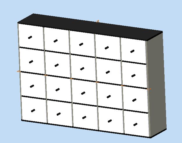
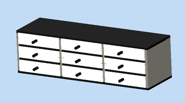
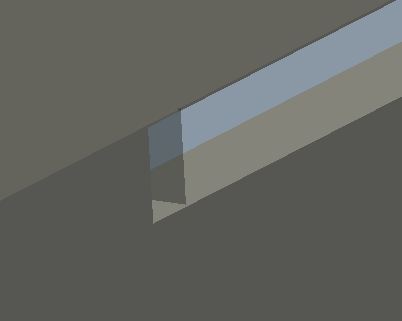
I planned for a small gap inside the slots for the rounded corners of the tool path to be hidden.
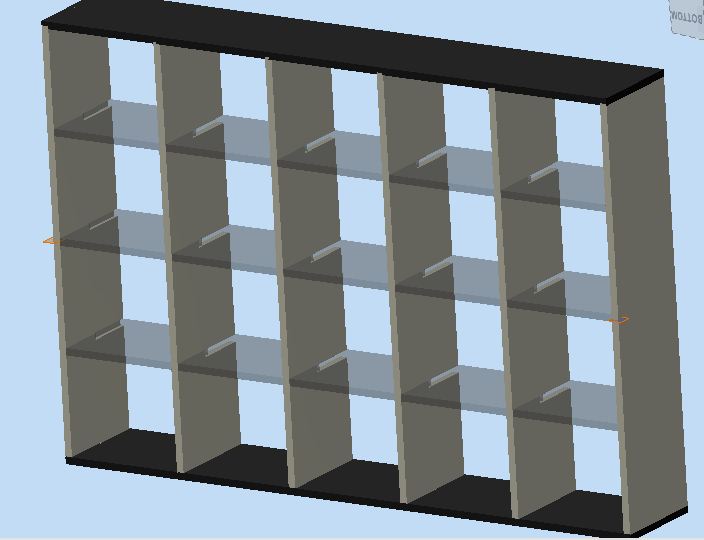
Another design variation was to create a 3D shape for the cubbies. This variation would have been easier to complete within the week.
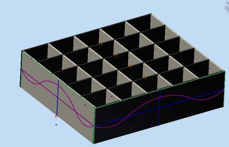
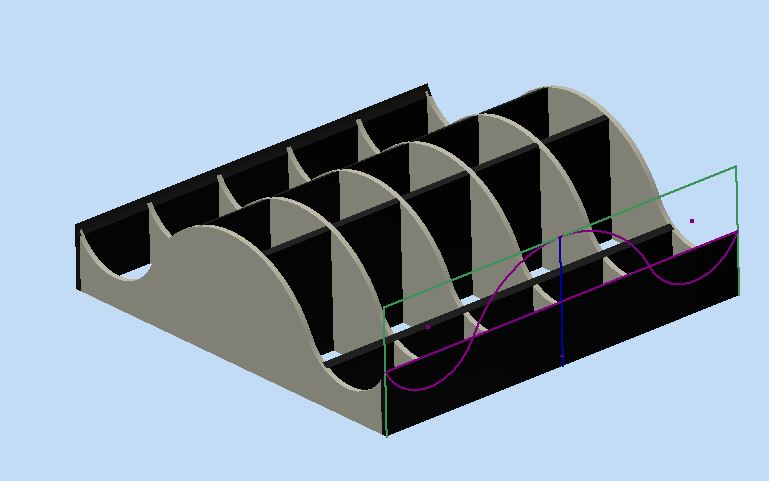
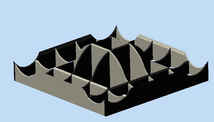
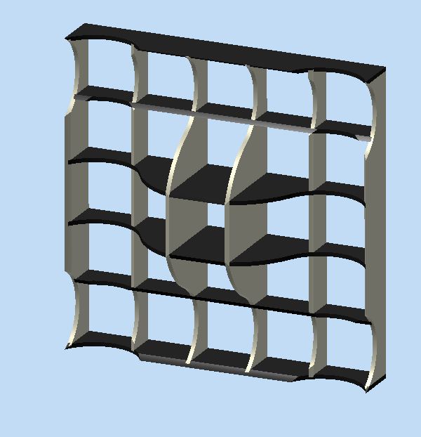
After assembly, there is layout. I created a new assembly called layout and manually arranged the parts on a new part called stock. Then deriving the assembly into a part, one just needs to select the front face of the stock as a sketch and all the geometry is ready to go.
Front Design
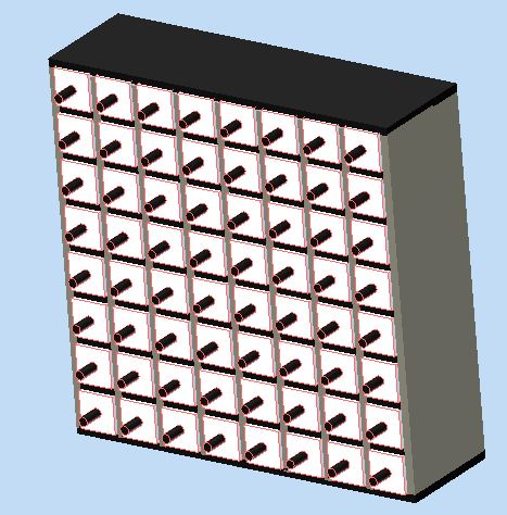
Now I wanted to etch an image on the front of the cubbies. No two cubbies should be the same. The goal was to have one cubby lock and only open when the rest are correctly arranged. (I'm thinking this would be fun in the room of a pre-teen).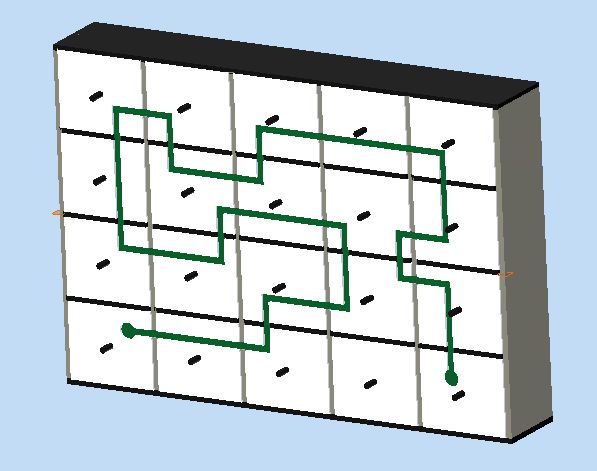
On the back of each drawer would be a piece of copper tape that looked like the front of the box. Connectors of copper tape would go from cubby to cubby. A connectivity test from an AVR would activate or deactivate the lock. (Lock design TBD).
Shopbot
The Shopbot is one cool device. I only got as far as cutting the shelving. The Shopbot was not available for the detailed cutting that I had in mind. Maybe next week.For the drawers, I wanted to do a traditional box joint.
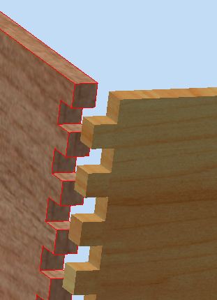
But the shopbot will leave rounded corners with a top down cut. No way to get a square peg into a rounded slot.
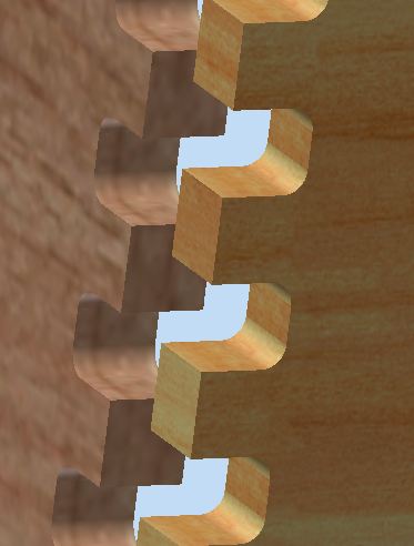
I would have to design some sort of jig to allow the Shopbot to cut square.
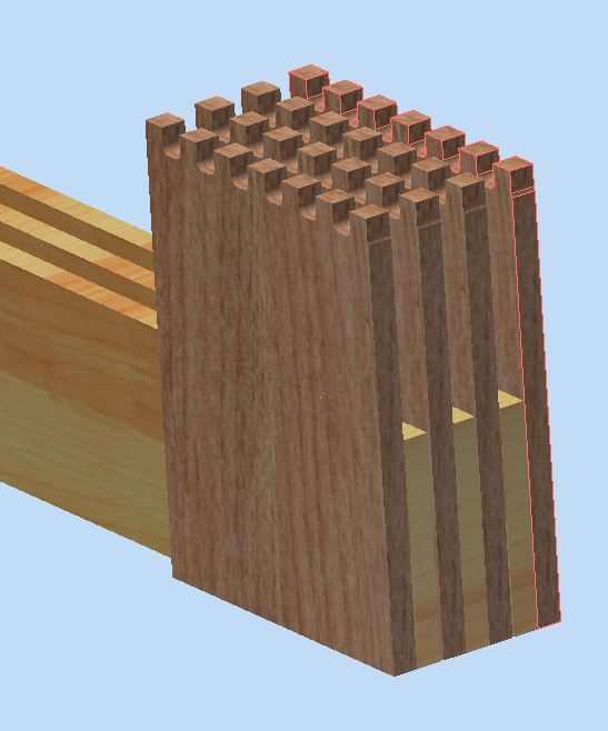
I don't know if that would fly. The clearance for the z on the Shopbot is not very large. I guess the sacrificial layers would have to be moved and then the jig could be mounted. Probably quite a chore.
Mistakes
Oof. Several.Job Interupt
I had to interrupt my job because the shop was emptying. This meant removing my stock from the table. Restarting it with the correct orientation would not be possible. I was able to cut some more pieces from the original stock. But the tight layout that I had was lost. Solution for next time: Keep a buddy around.
Collet not tight enough
The machine was chugging along cutting nicely. Suddenly I noticed it was not hitting the stock anymore. And then I noticed the cuts had been getting shallower and shallower. Ugh. Running the file again would not be a huge deal, except that in resetting the tool bit, the frame was bumped. So all the zeros (x, y and z) had to be reset. John and I futzed to try to get the xy reset. We set the z a bit high and ran the job. I tried to eyeball when the bit was just above the place it was the first time.
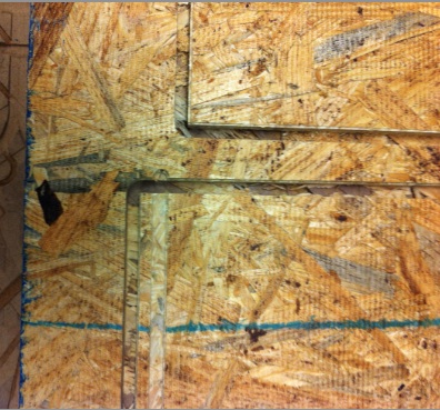
Some cuts did not go all the way through
This one I'm still surprised by. I measured the OSB as .43 inches. I set the cut depth to .46 inches. There was quite a bit of bend in my stock. Maybe that was part of the issue. Obviously a bigger cut through would work.
To address this, I ran the file again. Since I didn't want to have 3 passes of the machine, I wanted to set the start depth lower. The trick here: the end depth is added to the start depth. So I first said go from 0.0 to .46. Then I said go from .43 to .07. Thanks to Tom for this tip. The other idea I had was to set the step depth to a large number. Then it should try to do it in one pass.
Painting
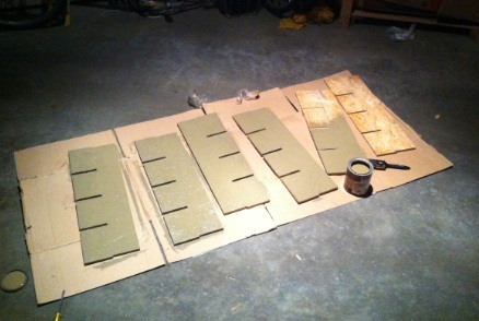
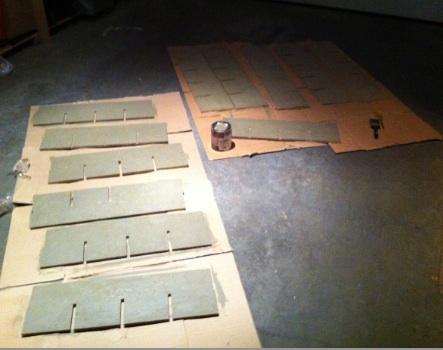
I sanded and bought some paint that Home Depot did not want. Two dollars for a quart of ugly green. Boy, 5 minutes into that project and I wanted a paint brush attachment for the Shopbot. (Cool idea!).