Final Project Concept - Sphere Companion Bot
For week 1 we had to come up with an idea for a final project. I'm interested in technologies to help other people understand technology, so I decided to build a spherical robotic companion bot. The idea came from BB-8 robot in Star Wars.
Sphere Companion Bot Initial Idea
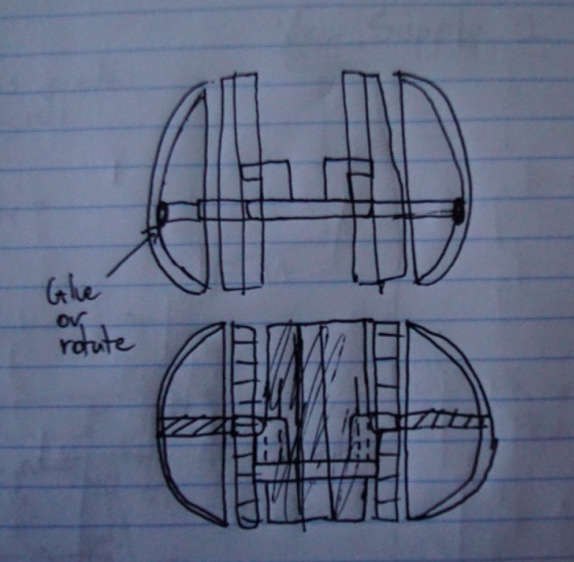
Initial Concept Drawing
The initial concept idea was to build a robot whose center would contain two wheels, and all of the cirtuitry and the machinery. On the side, we would have domes to give the robot the appearance of a sphere. This robot would use its two wheels in a tank configuration to move around.
Sphere Companion Bot Developed Idea
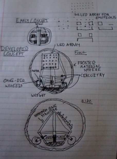
Improved Concept Drawing
I developed further the initial idea, and tried to put the wheels closer together to give it the appearance of a sphere. However, I gave some thoughts to the mechanics of the machine and realized that if it tipped, it could not be able to stand up. It would also be hard to ensure that the motors and the circuitry stayed in the same place and did not rotate with the motor accidentally.
I thought of the pitfalls from the original design and looked for inspiration in a magical place: Google. In the How Does BB8 Work site, I found an interesting mechanism for making a sphere moving robot (in particular mechanism 2 in the site). Basing myself on that mechanism, I decided to add to the design an LED array that could be used for projecting emotions: (happyness through a smiley face, anger with an angry face and red leds, etc.). Together, the mechanism and the LED board should allow me to produce a likeable helper.
Sphere Companion Bot 3D Modeling and Concept Rendering
Basing myself on the concept drawings, I decided to model the companion bot using Antimony. I chose Antimony because it seemed simple to use, and you could create complex shapes by just doing simple operations (union, subtraction, etc.). Using Antimony turned out to be very productive. I was able to build the concept in a day and export it as an STL. However, the program has a bug that creates a rendering problem and therefore it becomes almost impossible to continue modeling.
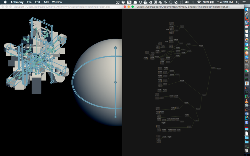
Screenshot of Antimony model and graphical bug
Having an STL file, I was able to export the 3D model into Blender. I wanted to prettify the model, and after seeing the capabilities of the Blender software in the recitation, I decided that I wanted to use that for realistic rendering.
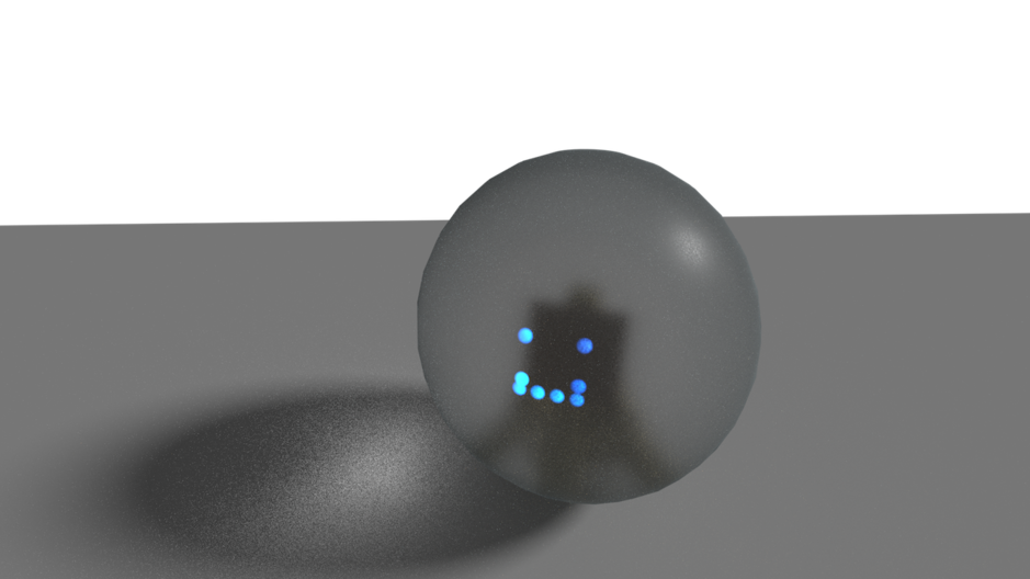
Blender Rendering of the outside of the companion bot
I spent a couple of hours simply listening to tutorials on how to navigate Blender. Once I had a very good idea of how the workflow went, I was able to import the STL files into the program and I moved them around until I got the body of the system (wooden structure that will contain the circuitry) inside the frosted sphere. I then added some lights to simulate the LEDs when they were turned on. I was incredibly satisfied with the renderings, and they were taxing on my desktop machine with a 980ti card.
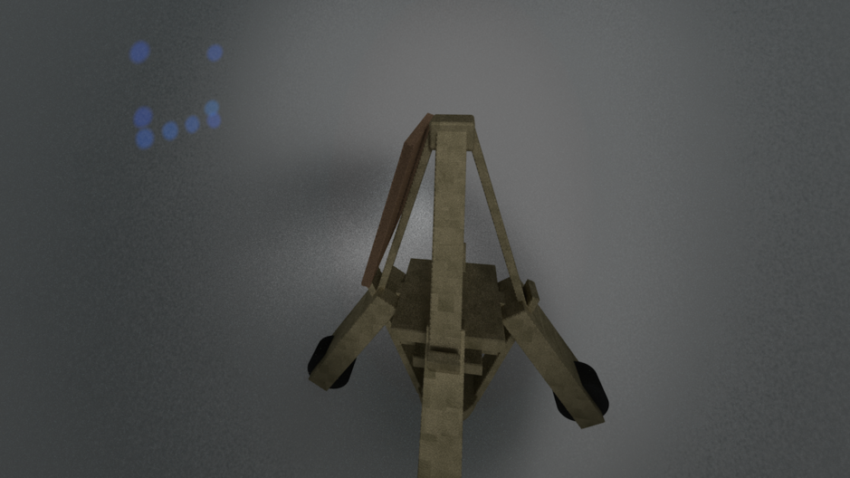
Blender Rendering of the inside of the companion bot
Hypothetical Features
Here are some of the possible features that the robot will have. These are by far not the final feature set, and may change.
- Talkative companionship (responds to audio)
- Smart home commands
- Following capabilities
- Remote control capabilities.
Updates
-
I have started to search for components, and have found omni-wheels and motors. I think I may 3D Print part of the structure or at least the LED array.
Motors Omni Wheels
I will try to start the circuit design for the LED array to convey emotions. -
I bought the aforementioned components and I have designed an initial version of the LED array. I still need to figure out how to connect the microcontroller to be able to control the entire schematics. Next week I'll modify the design of the body to be able to incorporate the motor and the wheels.
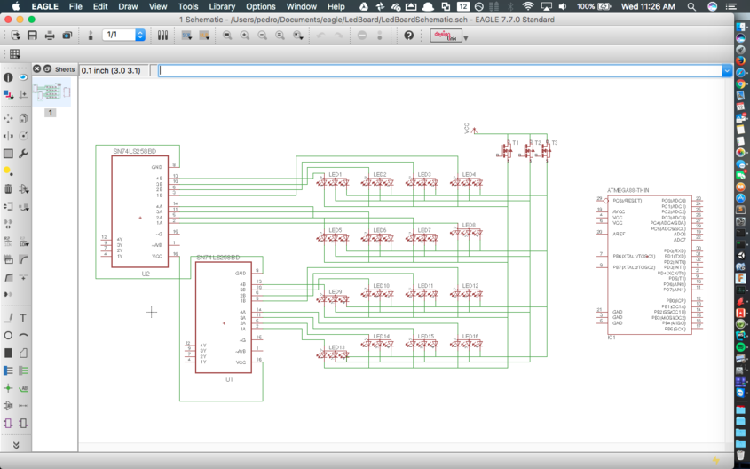
LED Board schematic
-
I updated my desing to incorporate the ATTiny44 instead of a multiplexer and decided to use the RGB leds that are in the Electronics lab. The wheels are delayed in shipping and I am going to start the remodeling of the body for the wheels and the location/sizing of the LED board.
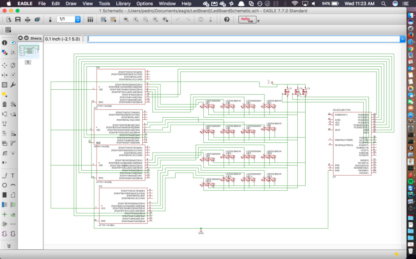
Updated LED Board schematic
-
Parts have started coming in. I have 2/4 motors and wheels. For a power supply I will reuse a battery that I had bought for a drone. I have to order in the motor shaft components that will let me connect the motor to the omni-wheels. I have not been able to put in much work, but the circuit and 3D printed chasis structure is coming up next. I want to mold in the sphere ASAP.
-
More parts coming in, the motors and wheels are now complete, I need the shaft to be able to join them. I need to put in some work on everything.
-
Motor controller done, need to incorporate cables to control it from an external source. Redesigning the LED board for 4th time. Will soon start the chasis.
-
I have the electronics design done, I milled all the boards, I stuffed some of them, but some of these got damaged. I need to re mill another motor controller board. I started fabricating the sphere. Vacuu-forming is the way to go. A colleague generously gave me some larger spheres that I may use if the fabricating does not work. I am currently designing the chasis and should have it by the end of the day to be able to send it to print. I just need to finish the spheres and the stuffing and test everything!
-
Sphere was fabricated! I used a foam hemisphere and tried to vacuu-form it. It turned out that the foam couldn't handle the heat and melted. To solve this, I had bought another foam hemisphere and covered it with kraft paper and aluminum foil. When I vacuu-formed this, it worked out great except for some wrinkles. I thought this would be bad, but it gives it a nice artistic touch.
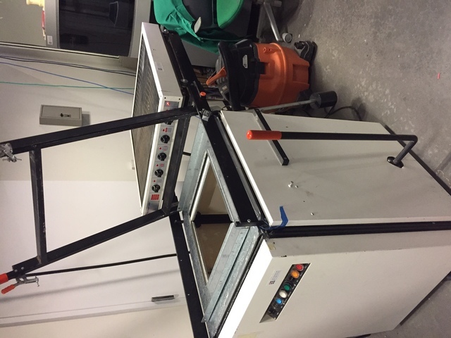
Vacuu-form machine
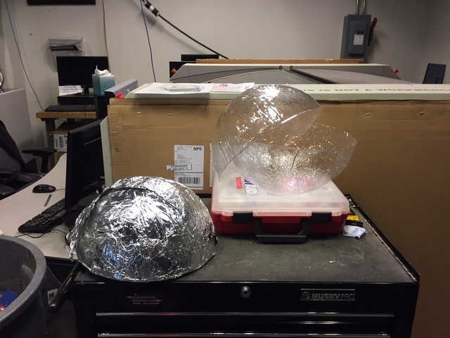
Vacuu-formed sphere
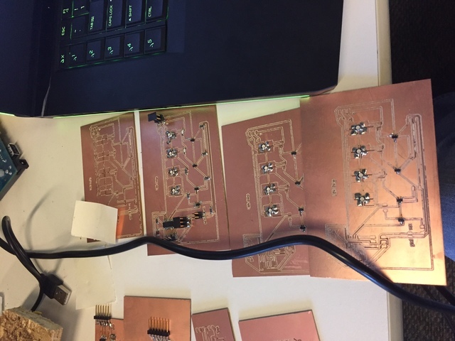
Also all the boards are milled, stuffing is in process. These boards are the motor controller and the LED array. These were tested individually and they work. The change to these boards is that what was originally connected by USB and FTDI is now connected by header cables. The power connectors will go to a regulator board that will be connected to a large 14.8V battery. There are 2 regulator boards, one for 5V and another for 12V
Test LED array

Test motor controller
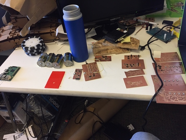
All the milled boards and pieces
Milled and partially stuffed LED Board
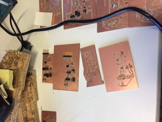
Milled and partially stuffed motor controller boards
I tested a 3D print chasis for holding a wheel, and a motor, and it turned out OK. The thickness on the block was too big, and now I resized it and I am currently working on the entire chasis for it.
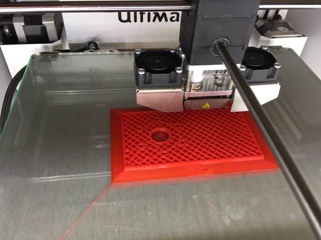
Test part 3D printing
-
The final crunch came! I was able to successfully design and print out a chasis. It took many attempts because the 3D printer was not very efficient when printing large (7" or more) things. I'll detail the building of the chassis, the assembly of the electronics and more below so as to not duplicate the data.
Official Documentation
What does it do?
The final version of the sphere bot is simply a robot that spins on its own axis inside a sphere using 2 motors. The original idea was to have a full fledged BB-8 robot that I could control and move around. Slowly, problems started arising and I had to downscale the project to simply turn on its axis instead of being able to move forward.
Who's done what beforehand?
The main components for the project were a sphere and the motor system. I did some looking around to find a sphere. Surprisingly, I checked to see if a sphere had been done beforehand, but the closest I found were using composites which, although turn out sturdy in the end, they are not transparent.
-
Here are some of the sphere makings that I found:
- Small sphere with holes using composites which doesn't help me out much
- Failed small 3D printed sphere
- Almost sphere with composites
- Giant inflatable sphere
What did I design?
The answer for this question is simple! I designed just about everything except the wheels, the bearings for the wheels, the motors, the raspberry pi, and the battery. More structuredly yet broadly, what I designed was this:
- Hollow transparent sphere
- 4 Motor sphere rolling system
- Chasis
- Motor controller and Controller software
- Power supply system
What materials and components were used, where did they come from and how much did they cost?
-
Here is a list of most if not all the materials used.
- Pitsco Omni Wheels (x4) ($29.99 each pair)
- PLA 3D printer material cartridge ($39.00 FabLab inventory)
- 3"x2" Single side circuit board (x4) ($0.18 FabLab inventory)
- 5"X4" Single side circuit board (x1)
- Attiny44 Surface mount (x4) ($1.18 FabLab inventory)
- 20MHz resonator (x4) ($0.43 FabLab inventory)
- FTDI Header Pins (x52) ($0.07 FabLab inventory)
- Quickie IDC Connectors 2X3P SNGL BM RCPL 30 microinch gold (x4) ($0.60 FabLab INventory)
- Quickie IDC Connectors 2X2P SNGL BM RCPL 30 microinch gold(x6) ($0.48 FabLab Inventory)
- 10k surface mount resistor (x4) ($0.01 FabLab Inventory)
- 100nF Surface mount capacitor (x6) ($0.12 FabLab inventory)
- 14.8V LiPo battery (x1) ($86.99 Location
- 20kmAh Phone Battery (x1) ($34.99 location
- 10uF Capacitor (x4) ($0.18 FabLab inventory)
- 1uF Capacitor (x4) ($0.07 FabLab inventory)
- 12V Regulator (x1 $7.42)
- 12V DC Motor (x4 $12.99)
- 3.3V 1A Regulator (x1) ($0.34 FabLab inventory)
- 620-1428-1-ND H-Bridge Motor Driver (x4) ($1.57 FabLab inventory)
- PBS Sheet 16"x16" (x2) (FabLab inventory))
- Raspberry Pi Model 3 (x1) ($35 Location )
- Jumper cables ($7.99 Location
- 12" Foam sphere (x2) ($12.99 Michael's at Porter
- Aluminum foil (FabLab inventory)
- Kraft paper ($5 Walgreens)
- Motor hub (x8) ($5, Location
- 4-40 0.5 inch screws (x24) ($3 Home depot)
- 3-32 0.75 inch screws (x16) ($6 Home depot)
What parts and systems were made and what were the processes?
-
Sphere
I tried to make this initially using the molding and casting and got good results, but they were difficult to scale up:
Here is what I made for molding and casting.
I also tried doing it with composites and got sturdy results, but they were not transparent
Here is what I made for composites.
I eventually found the vaccu-form machine. I bought a 12 inch foam hemisphere and went from there.
- I initially tested the vaccu-form machine using nothing. I would just let the material heat up until it formed a shell. This produced oval-like objects which were not what I needed
- I got 2 foam hemispheres from Michaels. I tried to vacuu-form the sphere with nothing, and the hot PBS melted the foam.
- I bought craft paper and glue and covered the remaining foam hemisphere to shield it from the heat. Then I covered that with aluminum foil to dissipate whatever heat came in.
- I placed my covered sphere in the vacuu-form machine in the middle and lowered it
- I waited for the plastic to start to melt approximately 2 minutes
- Once the material began to fall through slightly, I raised the hemisphere I had prepared until it came in contact with the material and turned on the vacuum
- I waited slightly for it to cool down and hit release
- I removed the excess plastic by cutting it
-
Chasis
I utilized a similar design as to what was in the How Does BB-8 work website. It consists of 4 wheels where each pair of the opposite wheel is
parallel to each other and perpendicular to the one next to it. I did my design in Autodesk Fusion as I was comfortable enough with it to be productive.
.png)
Chasis Design
I also measured the holes in the motors to make sure that they fit when I would combine them. It turned out that I had mismeasured the motor's mounting holes and I had to expand them with a hot iron later. Once I had the design done, I went to 3D print the parts. It turned out to be a complex print, so I broke it into pieces. The 2 pieces were the legs and the pyramid like body. Here is the design broken into pieces. The prints took in total a day, and then I went and hot glued them together. I had trouble getting the pyramid to work because the Ultimaker kept messing up when laying the foundation to make it easy to unstick. I found out that it was because PLA shrinks after it cools down and contracts, therefore messing up that the printer was putting. I after I figured this out, I removed the foundation that the ultimaker layed by default and put it to print and got the print successfully. As I said before, I realized that the holes for the screws were misaligned so I had to expand them with a hot iron.
Pieces
Assembled
After I had assembled the pieces I also noted that the wheel assembly was too large, and had to break off one of the 2 wooden blocks for each leg. The chassis turned out to be sturdy, but I had to expand it with some blocks of wood to fit the battery. -
Electronics
I usually like to work with electronics, but in the end this is what delayed the project. The motor boards that I had
milled and stuffed contained shorts that I had not been aware of. In trying to fix the shorts, I ended up messing most of hte
project up. I also had some trouble getting some regulators to work, but in the end the regulators worked fine.
Here are pictures of the boards that I designed and milled from scratch. I ended not using the LED arrays that I had
built because of time.
.png)
Regulator Board
The regulator design took a bit, because I was shorting the 12V regulator with the 3.3V regulator that I used. Eventually, I decided to drive the 3.3V regulator with the 12V regulator. I used a 3.3V regulator becuase the raspberry pi used a 3.3V logic and I would have destroyed it if I had suppluied the boards with 5V for their logic..png)
Failed regulator for the raspberry pi Design
This was a regulator that I ended up not using because the Raspberry Pi draws more than 1A and this regulator was not able to supply more than 1 amp. The connection worked fine though, just that there was not enough to supply. I ended up using a phone battery instead..png)
Unused LED board Design
This was a board I didn't have time to test out..png)
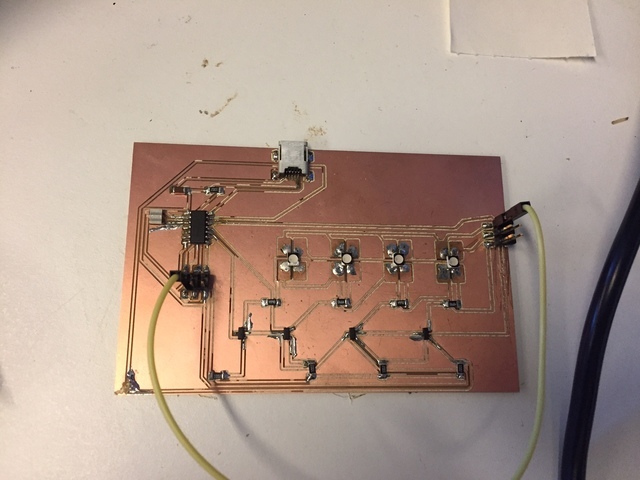
Motor Controller
This was the cursed motorcontroller that I had problems with. WHen placing the pins, I accidentally soldered them to places that there were shorts for ground. Other than this, the board worked fine when not shorted. Eventually I ended up ripping out by mistake most of the input pins in 3 of the boards and had to carefully glue them back together.
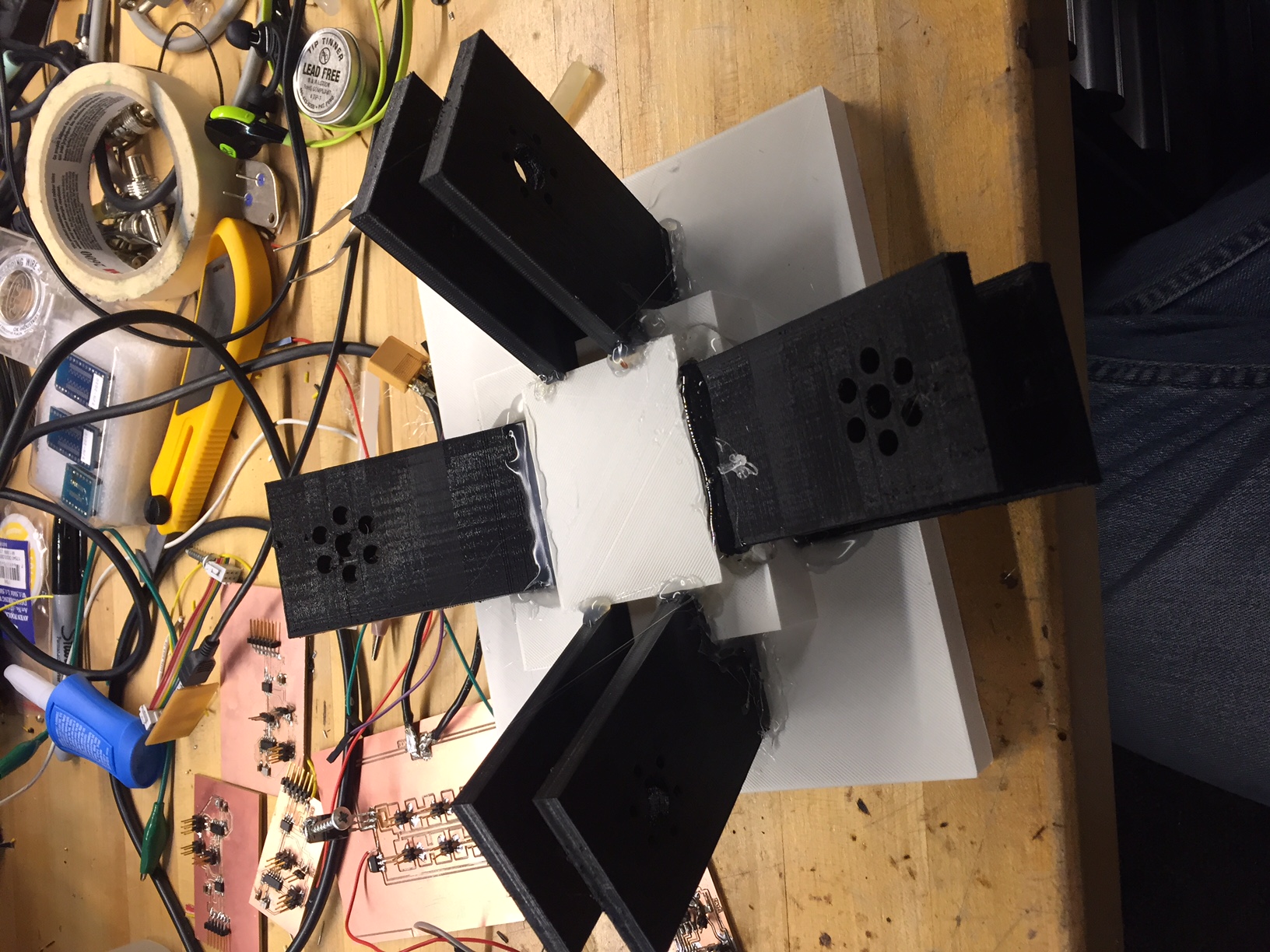
Boards Mounted into Chasis and connected
RIght at the end, I found out that my motors were too weak to drive the machine, so I decided to downscale the project even more to just make it rotate within the sphere. Here is a link to all of the eagle files - Software THe last thing was the software. I used processing in the raspberry pi in order to be able to utilize a mouse and a keyboard to control the robot. I also did a simple web interface to be able to access the device remotely. One notable thing about the software is that I got the boards to work in an active-low configuration. This means that the toggling logic was inverted (A high would mean off and vice versa). The software can be found here
The almost/mostly working prototype!
Here are some photos and videos of the device almost working Keyboard control No sphere working version
What questions were answered?
The main question that was answered was: Is it possible to make a BB-8?. The answer is yes. It is possible to make a BB-8, but you need to make a stronger sphere and a more robust control system to steady the robot. It is also expensive because of the batteries, motors, and shafts. Another question that was answered was whether a hollow transparent sphere can be made. The answer is yes and it can be made in pieces. With enough material, it could possibly be done as an entire sphere by putting the glued hemispheres and later simply cutting it in 2.
How was it evaluated?
The project was evaluated by whether or not the sphere rolled or not. Evidently, the system weighed too much and didn't have a control system to stabilize it. The result was that it rolled on its own axis, but it would not roll forward and could possibly tip over within the sphere. The project was half fail, half success. The robot was able to roll inside the sphere, but it was not able to move forward or stay in the same place. It is evident now that a control system was needed.
What are the implications?
The implications are that sphere robots can be built mostly using a FabLab inventory with some additional add ons. People can now build on the project and perfect it until it is in working order.
Files
Here are the files that I used for the renderings and models.