Week 7: Embedded Programming
26 Oct 2016 · 3 min readThis week’s assignment was to program our hello world board from two weeks ago. I’ve had a good amount of experience with embedded program, so I was pretty comfortable with this week’s material.
Following the instructions from here, I downloaded the starter code and Makefile. I used my own FabISP from a previous assignment.
Serial Echo
To program my board, I ran:
make -f hello.ftdi.44.echo.c.make
sudo make -f hello.ftdi.44.echo.c.make program-usbtiny-fuses # only necessary the first time
sudo make -f hello.ftdi.44.echo.c.make program-usbtiny
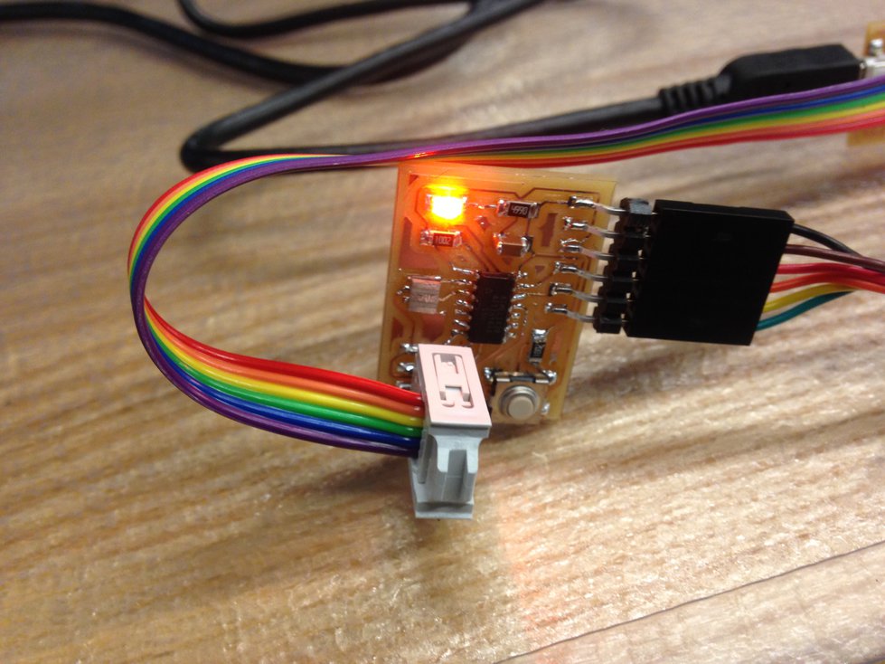
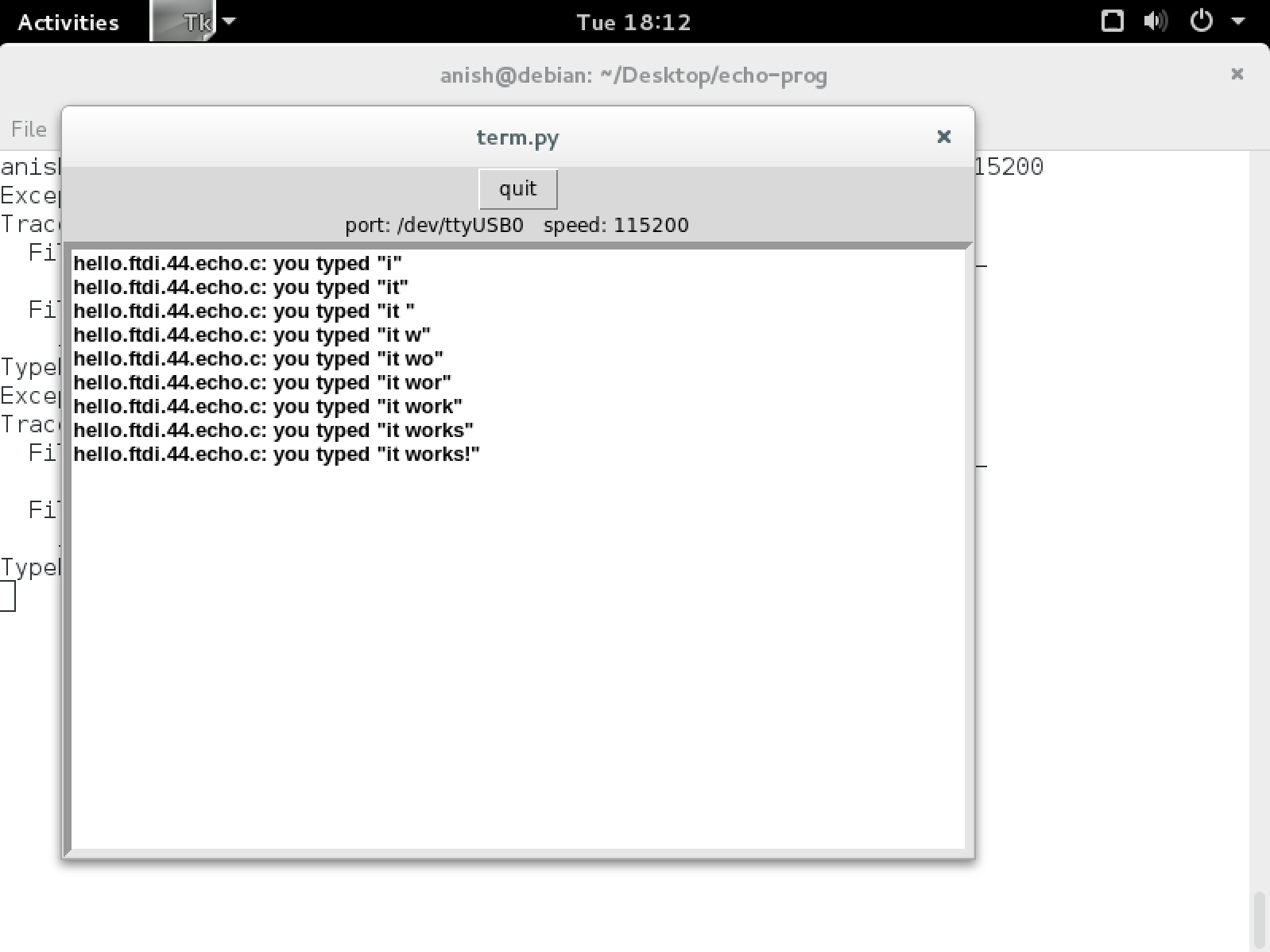
The first time I tried, it didn’t work properly. After debugging for a couple minutes, I realized that my cable was connected backwards. After correcting that issue, everything worked flawlessly. The sample program listened via USB serial and echoed characters back to the programmer. Here’s the program in action:
Blinking LED
After that, I decided to program the classic “hello world” program for embedded devices! I made my first blinking light program for the ATtiny44.
// blinking LED
//
// set lfuse to 0x5E for 20 MHz xtal
//
// Anish Athalye

#include <avr/io.h>
#include <util/delay.h>

int main(void)
{
    // set clock divider to /1
    CLKPR = (1 << CLKPCE);
    CLKPR = (0 << CLKPS3) | (0 << CLKPS2) | (0 << CLKPS1) | (0 << CLKPS0);

    // http://maxembedded.com/2011/06/port-operations-in-avr/
    // our LED is connected to PA3
    DDRA |= (1 << PA3); // set PA3 to output port
    while (1)
    {
        PORTA ^= (1 << PA3); // toggle LED
        _delay_ms(1000); // wait for a second
    }
}
Controllable LED
As my final test, I wrote a program that involves both the switch and the LED on the board. My program read input via the switch, and every time the switch was pressed, it toggled the LED. I made sure to include a bit of code for switch debouncing.
// toggle LED by pressing switch
//
// set lfuse to 0x5E for 20 MHz xtal
//
// Anish Athalye

#include <avr/io.h>
#include <util/delay.h>

int main(void)
{
    // set clock divider to /1
    CLKPR = (1 << CLKPCE);
    CLKPR = (0 << CLKPS3) | (0 << CLKPS2) | (0 << CLKPS1) | (0 << CLKPS0);

    // http://maxembedded.com/2011/06/port-operations-in-avr/
    // our LED is connected to PA3
    DDRA |= (1 << PA3); // set PA3 to output port
    // our switch is connected to PA2
    DDRA &= ~ (1 << PA2); // set PA2 to input port
    while (1)
    {
        if (PINA & (1 << PA2))
        {
            // toggle LED
            PORTA ^= (1 << PA3);
            while (PINA & (1 << PA2)); // wait
            // wait a little bit longer as a debouncing measure
            _delay_ms(10);
        }
    }
}
Here’s the program in action. Well, it’s a picture, so it’s not really “in action”, but close enough: