Final Project: Using Gesture Tracking to Trigger Sound
- Overview: This wirelessly connected device will allow the user to trigger 3 different cave environment sounds with 3 distinct gestures. The device is encased in silicone, wirelessly connected, and powered by a battery.
- Target Audience & Application: This device, tentatively called NEXUS is part of my educational project StoryLabs. I'm interested in using technology and storytelling to help build empathy between students (ages 8 - 13) across racial identity groups, inspired by Augusto Boal's Theater of the Oppressed and Gordon Allport's intergroup theory. As part of the curriculum, students work together to create a fantasy universe and must solve problems that mirror ones from our real-world society. Students act out potential solution, like in Boal's forum theater; that's where NEXUS comes in. All students in a group can participate by layering background sounds, incorporating symbolic gestures, etc. An early prototype of this gesture-tracking device allows students who shy away from the spotlight to participate fully in the action scenes. By making a certain gesture, students can trigger sounds to underscore the scene. For example, students may be exploring a cave to find hidden research that will heal a sick village. As they explore, a wave of the hand may trigger the whooshing of bats, or a fist pounding on a table top may trigger the sound of resonant footsteps. Sound and gesture tracking offers another way students who have differing learning styles can stay engaged in the development of the story.
- Similar Existing Examples: IRCAM: IRCAM, an electroacoustic music research organization in France has created Mubu, a Max MSP patch that can learn gestures. One application that has been done is the "Gestural Sonic Interaction: The Virtual Bath Tub," which connects MAX to LeapMotion to play water sound samples controlled by hand gestures.Mogees: Mogees is a vibration sensor device that people to turn any object around them into an interface for sounds. While it doesn't track accelerometer data, it also has a machine learning component, so that the device learns how you want motion and sounds to be paired.
- Materials & Components + Costs:
Item Price Vendor Quantity 9V Battery $2.95 Amazon 1 Magnets $3.20 K & J Magnetics 14 Electronic parts ~$2.00 Inventory N/A ATmega328 $2.87 Inventory 1 Mold Star 20T Silicone Rubber $30.11 Amazon 0.5 TOTAL $41.13 - Parts & Systems: To create the outer shell, I am using casting and molding techniques to create a silicone layer. Inside, for structural support, I am laser cutting acrylic to assemble a pressfit frame. The electronics are PCBs, or printed circuit boards that I have wirelessly connected through Bluetooth. There is one main board with an ATmega328, a RGB LED breakout board, an accelerometer breakout board, a battery breakout board, and a bluetooth board. For the computer application, I am using Max MSP and Arduino IDE to build the computer program interface.
- Processes: Laser cutting, casting and molding, electronics design, computer controlled cutting, computer controlled machining, embedded programming, input devices, output device, networking and communications, interface and application programming
Progress made during weekly assignments:
The video to the right shows my progress on 11.30.16, demonstrating the sound and gesture tracking functions. The video was for my final project in Karen Brennan's T550 course.
- Project Development:
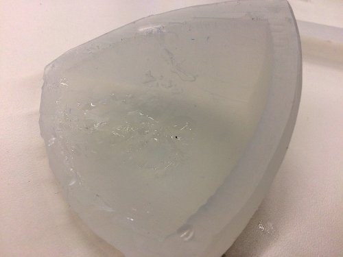
Day One: Now that final develpment has rolled around, I am fortunate that I basically have a working model to build off of. My game plan is to return to each week's assignment, and refine what I created. First off, during the molding and casting week, my mold didn't lock together, so each wall of my object was a different width. Also, I didn't quite figure out how I wanted to lock the two sides of the triangle together. After discussing with Rob, I decided to try using rare earth magnets. After sharpening one end of an aluminum tube, I bore out a hole for the magnet. I didn't need to fret about the strength; the magnets are so strong, they get pulled out of the silicone. I will order thinner magnets online, and see if that decreases the strength.
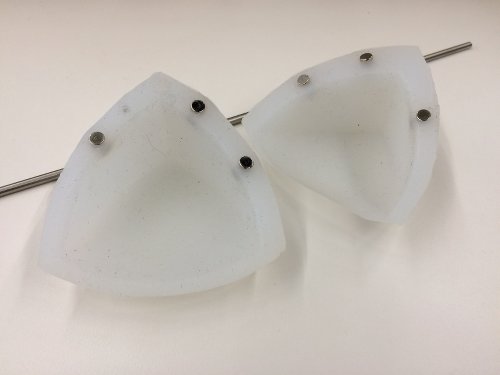
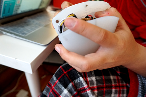
Testing the strength of the magnets in silicone
Day Two: I decided to cast a much larger version of the silicone case. I won't have time to redo all the electronics on smaller PCBs, so I thought this was the easier method. Of course, nothing in this class goes exactly as planned. I had a really hard time melting the wax, as the hot plate would smoke like crazy. Even without any spills. I set off the fire alarm (only for a few minutes) but that was not fun on a very cold Boston day. I moved downstairs and worked under a hood, so crisis averted. I used an old Starbucks gift box, and since it was made of waxed cardboard, the wax block easily came out! Machining went fine, except that I measured the box wrong bby 0.25 inches (stupid mistake, I know) and one wall of my mold is very precariously thin.
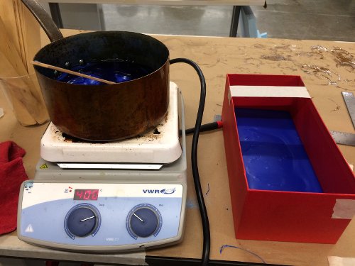
Melting wax on a hot plate
Because of my mistakes in measuring, the ShopBot did not do the finishing cut with as much smoothness as I would have liked. I used the 1/4" straight drill bit for the rough cut (make sure to use one where the flutes are going up) and the 1/8" drill bit for the finishing cut. I used sandpaper and sanded for a very long time to remove most of the stripes. Still, I ran into plenty of problems while casting. First, I didn't mix enough, and part of the inside wall stayed gummy and didn't cure properly. Then, because the wax mold bowed in when it cooled, the lid of my mold did not come out flat, causing extra silicone to bubble over the sides, which was difficult to perfectly trim. Tip: Even when rushing during the finals week, measure twice! My measuring mistakes ending up costing me a lot of time in post-processing the casted object. Also, when scaling up to a larger object, many of the mistakes are a lot more obvious! In the end, I ended up using the silicone with the gummy interior because the edges lined up best with the magnets. And, since the mistake is on the inside, it's not super obvious.
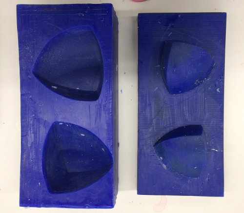
New mold after a lot of sanding
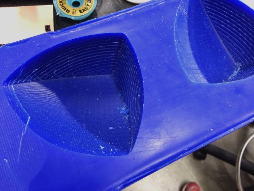
Stripes from the machining process
Gummy interior from the Mold Star not setting quite right
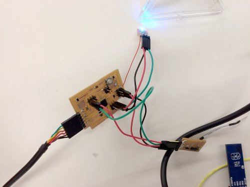
Day Three: Today, my goal was to map the accelerometer values to a RGB LED, so I started off by creating a breakout board with the RGB LED and its accompanying resistors. Unfortunately, my fabduino didn't not have any more free VCC pins, so I soldered a Frankenstein wire to "make it work." Once I wired everything up, I tackled the coding. After consulting with Dixon, he suggested that I check out the mapping function. Basically, the code ended up being fairy simple. I declared variables r, g, b and then I mapped acceleration data (x, y, z) onto color intensity.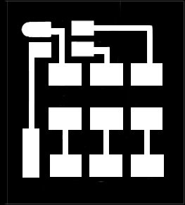
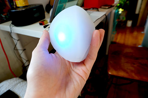
The code worked, and now I have a beautiful light that changes the intensity of red, green, and blue light based on accelerometer data inside my device, and a device looking less like a silicone body implant!r = map(event.acceleration.x, -15, 15, 0, 255);
analogWrite(8, r);
g = map(event.acceleration.y, -15, 15, 0, 255);
analogWrite(10, g);
b = map(event.acceleration.z, -15, 15, 0, 255);
analogWrite(9, b);
Day Four: Today can be subtitled "How to Make Every Mistake Possible While Making a PCB." For the last day before presentations, I thought I could quickly whip up a battery board and get everything powered through a 9V battery, and call it a day. Well, it actually took me a whole day since I made many silly mistakes. First, I looked up the wrong datasheet for the 5V IA regulator, so all of the pins were switched, causing much confusion. Then, I didn't properly connect all the ground traces, causing my board to get so hot, it liquified the sauter and burned me! Then, after making a new board, the battery was actually dead. Finally, there was a sliver of copper at the edge of the board leftover from the milling process that had connected to some solder, and that was causing havoc on my board. Eventually, everything did work, and I retested everything by connecting to Bluetooth. Whew, mission accomplished! Now, for my final challenge, I needed to FIT everything inside my silicone encasing. For this, I decided to bring back laser cutting and create an acrylic pyramid to hold all the components together.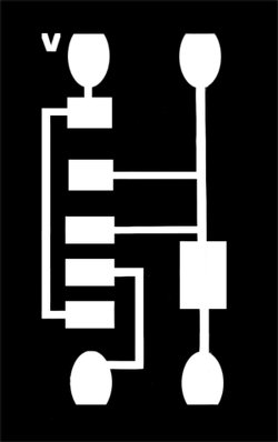
Using Adobe Illustrator, I measured my 0.1" acrylic sheet and drew one side of the triangle and rotated the duplicated line 60 degrees until I created an equilateral triangle. I exported to .dxf and laser cut the acrylic easily. The smell was not so pleasant, but the cut came out beautifully! I fully expected to do trial and error, and for the first time in this project's progression, I didn't have to! I'm glad I chose to laser cut rather than 3D print because the ability to dissemble the triangle made it a lot easier to squeeze in all the components at the end. I also love that the transparent acrylic allows for my LED light to shine through. Originally, I had plans to make shelving inside the pyramid for all my components, but there's barely enough room to even fit the pyramid, much less a pyramid with shelves. I guess that's why you go through spiral development. Glad I didn't waste too much time figuring out the design of the shelves.
Melting wax on a hot plate
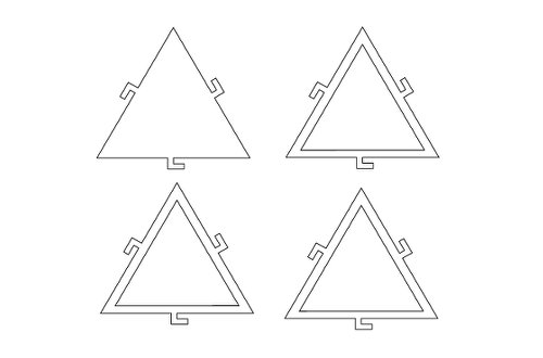
Illustrator Design
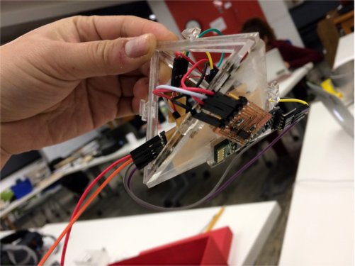
Assembling!
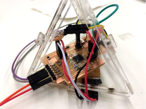
Squeezing components into acrylic triangle
Accelerometer taped to flat acrylic surface
Everything works by battery!
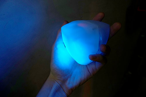
Glowing at night, just for fun
Finally, I loaded up the Max patch and the accompanying sound effects for final testing! I sourced the sounds from freesound.org and FreeSFX. For whatever reasons, my students love exploring cave scenes, and there's plenty of strange and mysterious sounds that can be played during such an adventure!
Cracking Earthquake by uagadugu
Single Strike of Match from freesfx
To get the program to work, click learn 0. Then, press and hold 1 to record the gesture. Hold 2 for gesture 2, and 3 for gesture 3. Then, when finished recording, hit stop. Then, click follow, and hold q while doing the gesture. If the accelerometer data matches properly, you'll hear the matching gesture!
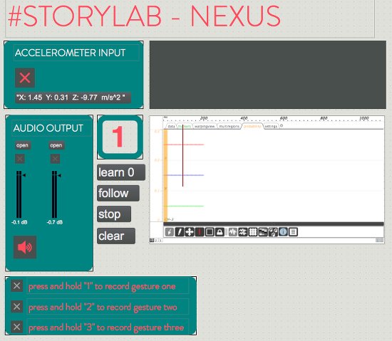
User Interface Design on Max MSP
- Evaluation: To be honest, I'm very pleased with how everything turned out. The final device is pretty close to what I imagined at the beginning of the class, and I accomplished all the features I intended to include this semester. Given how little I knew when I began, I think this project was the appropriate amount of challenge - it was definitely frustrating, but ultimately very rewarding.
- Future Development: In the future, I hope that the device can be streamlined so there aren't so many moving parts and can be condensed to a size that works better for child-sized hands. Also, it would be awesome if the device allowed you to record any sound, and then map it to a gesture. Finally, more work needs to be done on the user interface side so educators can use this in the classroom.
Schedule: