
Antonella Masini
Learns How To Make (Almost) Anything

Learns How To Make (Almost) Anything







I am a junior pursuing my Bachelor in Mechanical Engineering at MIT, while minoring in Computer Science. I am passionate about Robotics, Product Development, Prototyping and Product Design - while I also love to run, practice Brazilian JiuJitsu, draw, play the flute, teach and dance. I spent my last summer building a robot that ballances a ball on a uniform plane in Barcelona and everytime I go back to Peru (where I am from) I build wooden houses in rural settlements for families who can't afford it as part of an NGO program.

During my junior Fall (September - December 2019) I will be taking 6.943: How To Make (Almost) Anything. In this class I hope to learn from how to properly use a soldering iron to build big scale machines. Welcome to the website where I will document my journey! SPOILER ALERT: Achievements and dumb mistakes included. You are allowed to laugh. If you are still curious about this smol Peruvian, go and checkout my personal website!
PS: If you know of someone who is hiring undergrads for Summer pls hit me up ;) hehe.


We were told that by the end of the semester we would have to present a final project. I am very excited but also a bit nervous because I want to make something interesting but I fear that I will end up disappointing myself. I started brainstorming a while ago, I’ve learned throughout the years that I’m a very visual person and so I started organizing my ideas in the following diagram:

After a lot of thinking and talking with Anthony (btw, thank you sosoososo much for being always so patient with us) I decided to look more into the table with a map of the world.
This class means a lot to me and so for my final project I want to do something that has an impact in my community. I have realized that even though most of the people here at MIT seem to be super welcoming with international students, a lot of people have no idea what it is like to live in different parts of the world, myself included. It was only thanks to living in an international fraternity that I got a whole new perspective of the world.
Yup, it is exactly because of that that you should care.
As you can see, it is important to raise cultural awareness not only for the benefit of intenational students but for every single person who goes to MIT. In addition, this could also ease the transition of an international student to studying in the US. It might be hard to relate to how an international student feels so I wrote this poem in an effort to explain the feeling that almost all of us (internationals) share:
Centimeters to Inches
Peering out of the plane’s window,
a shy, tanned girl arrived
looking from left to right
trying to find something she’d recognize.
But the “hola”s from home, the kisses on the cheek,
they were all gone.
Replaced by grey handshakes and “how are you doing”s
lacking response.
The shy, tanned girl stepped down from the plane and learned how to laugh
Typing “h”s instead of “j”s so that they could finally understand. 1
She spoke in centimeters but got used to the imperial inches
and screwed up a recipe or two…
How could she know what an ounce of milk was supposed to look?
But as days passed, the shy tanned girl learned
that measurements mean much more than that.
“The amount of space between two points” was not enough to describe
the excruciating pain that she felt in her heart.
Distance is much more than being far away,
It is to know how a welcome hug tastes,
Turning it into your favorite flavor
And doing the impossible to not forget.
Distance is learning not to say goodbye
Because it tastes so bitter and sad,
So instead you mutter a “see you later”,
Grab your bags and try not to look back.
Distance is to have your brain in one country
and leave your heart kilometers behind.
It is to acknowledge that you’ll be that friend that’s never there,
And that now you are the invisible daughter for your mom.
Distance is to gradually lose your accent,
And those words that you used to love.
Replacing them by “lol”s and “omg”s,
That’s what kids say nowadays, no?
Distance is the birthdays through Skype,
The long voice notes through WhatsApp,
The one million “I miss you” through texts,
And the longing for that eternal summer you left.
Distance is to learn how to live on your own,
To become stronger and independent.
It is to have some incredible days, and some really bad ones too, that’s also okay.
It is to feel completely lonely but to suddenly realize
That your people are still there, only a few texts apart.
Which means that you will never be alone,
Because sometimes the heart can travel where your voice can’t go.
Because distance separates bodies, it doesn’t separate hearts.
Because for a few weeks a year
the now-not-so-tanned girl will return,
And with tears in her eyes she’ll say:
I’m home.
For my final project, I would like to make an interactive table that will raise cultural awareness in the MIT community. I started with the idea of making a map of the world that would have an LED in each country. Then, with the pressing of a button (or maybe detective touch) the user would be able to see by year how many students from different countries were studying at MIT. I would get this data from the International Student Office website.
However, during my checkoff Alexandre made me realized that it wouldn’t be much fun to solder 196 LEDs …. Yikes, I didn’t expect the world to have so many different countries. In addition, he told me that it would be very hard to make the schematics and also to connect so many LEDs to one microcontroller (because there are not enough pins).
Solution: Alexandre had the great idea of, instead of using countries to divide the world, use a grid. Then, use Charlieplexing a technique that allows you to control many more LEDs than you have pins. The exact number of LEDs that you can control with a given number of pins is given by n^2 - n where n is the number of pins used (i.e., 3^2 - 3 = 9 - 3 = 6 LEDs using only n = 3 pins).


However, this was just an initial idea. I realized that just a bunch of LEDs would be quite boring for my final project and so I started thinking about using capacitive touch to allow people to touch a country and then the response would be a screen outputting fun facts about it. However, even for this, I would need to use Charlie Plexing which, even though it solves the lack of pins problem, I would still have to solder a lot of pads (which means a lot of complex debugging to do). This seems quite an impossible task to achieve before the semester ends... and so it was time to do some alterations to my initial idea. Sadly, Junior Fall tends to be a heavy semester for most Mech-E students and so, in the end, I had to settle on something more simple but I want to at some point do something more complex because I was really passionate about the initial idea.
Map/ LED circuit
Table:
Interactive Component
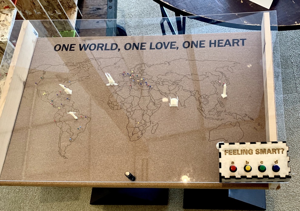
My final project is an interactive table. I wanted to be fun in order to attract as many people as possible. Because of this, I decided to make it like a game. It will have a map of the world, to grab people’s attention. Then, I will have 4 buttons labeled as “a” “b” “c” “d” and a screen that will output a question about a country and give four options. The “player” will have to press the button that they think is the right answer and then the screen will tell you the correct answer if you answered incorrectly.
I haven’t seen a project exactly like this before but I got inspiration from different things. One of the main sources of inspiration comes from an interactive table made back in 2013 which is basically a giant fully functioning control for Nintendo games. I initially wanted it to be touch-sensitive because I read about how it is becoming popular for museums to have interactive multitouch displays where you can just select items and information about them will pop up. They claimed that people were more involved and seemed to express more interest after the displays were installed, which is something that I was looking for my table.
I designed the whole table legs in SolidWorks (this was actually quite a hard task since they are made out of folded cardboard and it can be quite difficult to visualize the length dimensions for the flat sheet of cardboard when the design that you want is in 3D. It was because of this that I had to design an assembly part with the objects designed in 3D as individual parts. I also drew the map of the world in Illustrator and designed the board for the ESP32 (taking Neil’s as a guide).
Since I’m a broke college student I couldn’t afford to buy very expensive components for my project so I tried to use what was already available. Because of this, I decided to use an acrylic sheet as the top part of my table and cardboard for the legs. I actually think this was a great choice since it forced me to think creatively and do as much as I could with a few materials. The corkboard cost around $15, the spray paint $6, the pins for cork board $7, the spray lacquer $10. So I spent a total of $38. I’m not sure how much do the components or acrylic that I got from the EDS shop cost.
I judged my project using three different criteria:
So, overall I think that I succeeded. It was not my initial plan and ended up being a simplified version of what I first envisioned but it accomplished its main purpose and, given the limited time that I had and the amount of honest effort that I put into it, I think that it was a big success and I’m so so so proud of myself for building it from scratch and finish it.
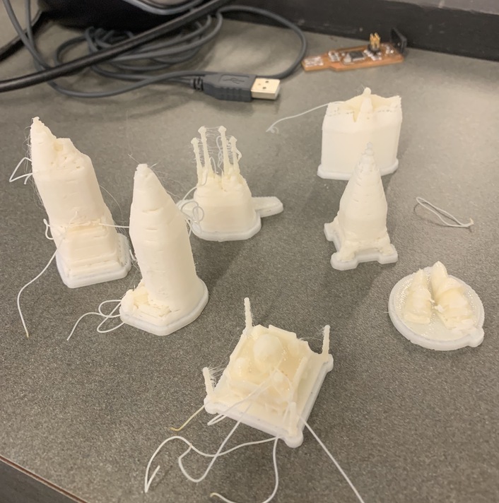
In order to make my map more attractive, I thought that it was going to be a good idea to 3D print some landmarks from around the world. I then started looking for files already made online and found a bunch of really good ones! I downloaded the files and was about to print them when I realized that the files were huge and so I had to scale everything down by a factor of 0.1. Some of them were so big that not even a factor of 0.1 scaled them correctly so I decided to not print those (sad, because there were some really cool ones like The Chinese Wall).

In the end, they turned out pretty cute!!!! I also designed in SolidWorks the MIT dome but in the rush of the moment, I completely forgot to 3D print it. I will probably do it when I come back for IAP.
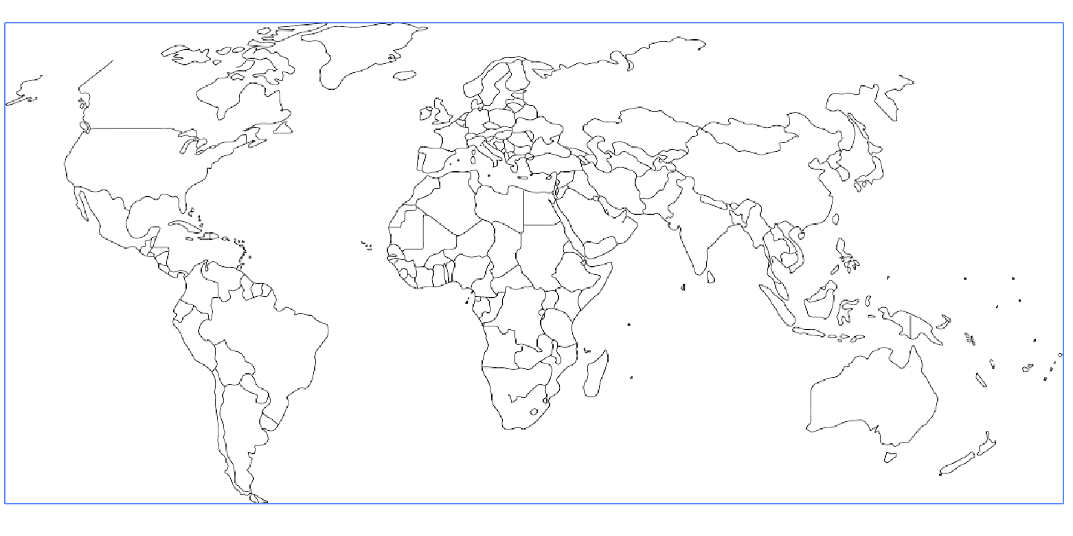
I had a 23''x35'' cork sheet sitting in my room since last year because I bought it from Amazon for a project but never ended up using it. I decided to use this as the top part of my table. I then looked for a picture of a black and white world map. I found a couple but sadly none of them had a high enough quality to convert them directly to vector form in Illustrator (for laser cutting). Because of this, I had to download the best image that I could find (with good enough quality), open it in my iPad in Adobe Procreate and trace it over in order to improve the quality. I finally managed to do so, imported the file, opened it again in Adobe Illustrator under the "tracing" option in order to convert it to vector form. After trying different settings I decided to use the one called "technical drawing" because it gave the best results. I then added a quote on top of the map, rasterized the image so that it was visible when converting the file to SVG. format for laser cutting.

Next step was to look for a big enough laser cutter. I was going to use the EDS laser cutter but sadly it was not working so I had to go to the Arch shop and use theirs. I wasn't very familiar with their software but thankfully Jennifer O'Brien was there to help me set up the machine. It turned up to be pretty similar to the one of the EDS, although a little bit more complicated.

I then decided to turn off the autofocus in order to be able to modify it. The reason for this was that I wanted my world map lines to be as thick as possible so that they would be easy to see. Jennifer told me that that laser cutter's lense was specially bought for architecture students that need a very thin precise cut for their drawings. I didn't actually need this and so I started playing a bit with the focus in order to widen the laser.

I made some trials by only laser cutting a few of the smallest islands near Australia

and when I found the perfect distance between the laser and the bed I started laser cutting the whole map. It turned up looking pretty cool!!!!! I then decided to paint the letters of the quote to make them pop. However, I didn't have paintings and so I used coffee. Surprisingly, they turned out really nice.


For this week’s assignment, I chose to focus on a folding and cutting technique that you can do with the Large Scale Cutting machine that is in the CBA shop: the Zund G-3 L-2500 which is a multifunctional digital cutting system.

On Friday 6th at 9:30 am I went to the CBA shop to get trained for the machine. It was very interesting and the machine was indeed impressive. I learned that it has three modules, each one with a tool and blade.
Steps to use the machine:
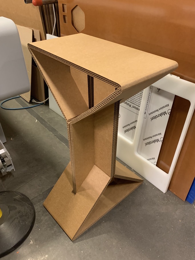
It took me a while to make the design. I wanted it to be something with an interesting geometry that would take advantage of the cardboard foldings that the Zuno machine lets us do. I started the design in Solidworks but after a while of sketching random lines without any actual progress, I realized that it was time to grab a paper and start brainstorming there. After a while, I decided to make the supports of my table for my final project, implementing the foldings and slots. I am aware that the material used is cardboard, which means, on the first glance, is not the best material for building a table, However, I wanted to face a challenge and I also think that it is important to explore more sustainable options when building new things.
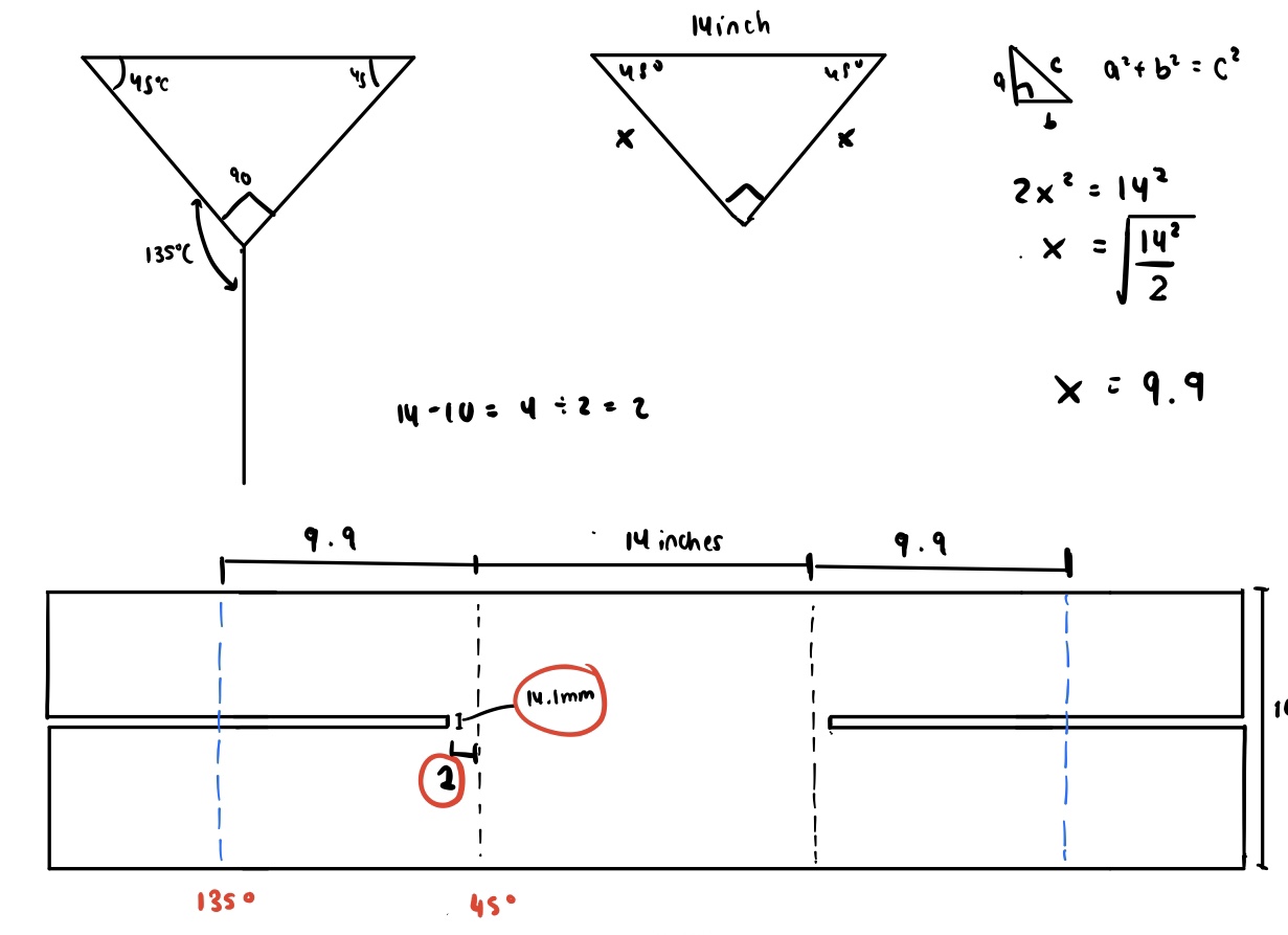
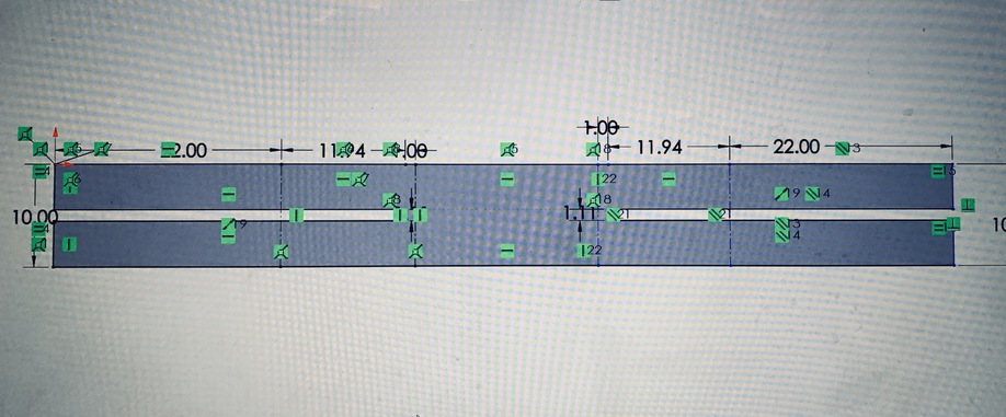
While designing the supports for my table, I had to do more calculations than what I initially thought. I also realized that the stability of my structure is correlated with the size of the triangular part of the geometry. I had two types of foldings: one of the 45degrees and another one of 135 degrees. I also decided to make the 3D CAD in SolidWorks in order to make sure that the pieces would fit together in the best way possible and that there were no errors in the design. Thankfully, I did this because I realized that the space I had left for the slots was the width of the cardboard but it should be instead twice the width of the cardboard.

On Sunday 8th I went to the CBA shop to cut the cardboard. However, we run into some issues. I had made the part in SolidWorks, which from what I know, doesn’t have the option of layers. Because of this, I had to open the part saved as a dxf in Rhino. In there, I had to change the layers and save it as a dxf. This, although it sounds trivial, took me a while because neither Patricia nor I knew how to do it. After finally getting it done, I saved the new dxf file (with layers) in a USB flash drive and took it to the Zund. However, we ran into problems there too. The first problem was that when we opened the file in the monitor connected to the machine, the dxf had scaled down. After several minutes trying different thinks we realized that the Zund had recognized the design as if it was made using mm but I had used inches so we just scaled it up by multiplying everything by a scale factor of 25.4 to convert it into inches.


The second issue was that the machine only makes cuts on one side. However, my design would require a cut for an internal angle but also a cut for an external angle. There were two solutions:
For the first try, I tried the second option. However, something weird happened with the machine that, as you can see in the following pictures, didn’t make the proper cuts for the respective cut angles. S A D... but persistence makes perfection.

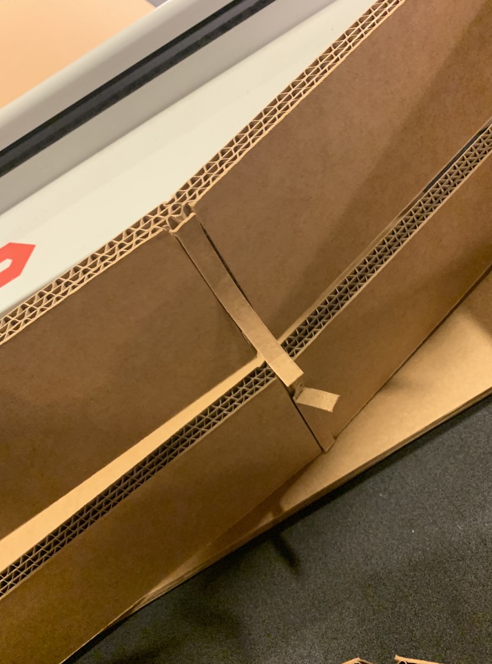


On Monday 9th I edited again my SolidWorks part in order to enlarge the triangle portion a little bit to make the structure more stable. I also decreased the length of the slot in order to make it fit exactly.
I then went to the CBA shop again at 2pm, opened Rhino and imported my dxf files. I set the layers to their corresponding lines, save this new dxf in a usb flash drive and took it to the Zund. There, Patricia helped me to put a new cardboard on the bed of the Zund and to operate the machine. She first had to change one tool but after making sure that they were tightly held, to avoid any damages, we were set to go.
First, we opened the CutManager and made sure that the correct materials, thickness and tools were selected.

Then we plugged in the flash drive and opened the DXF in the CutEditor. There we scale it with the correct factors and then set the layers to the corresponding tools:
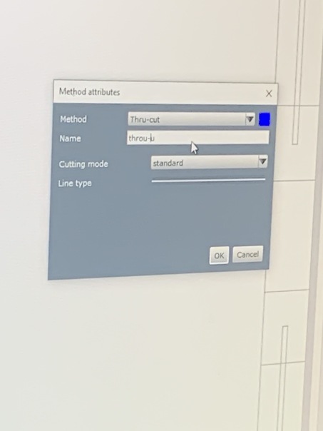
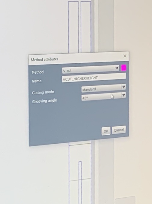
We then saved it and sent it to the Cute Cube. There we matched the layers with the respective tools.


We then aligned the cardboard with the machine by running the laser dot along the edge of the material. Finally, we set the reference point and started cutting... We waited and then took the cut part out, bent the parts and TA DAAAAAA IT WORKED!!!!!!!! 3 more to go!

In order to accelerate things, we decided that it would be a good idea to run the commands without taking out the cardboard and putting it again and loosing all of the assignments of layers to tools. By doing so and just changing the reference point (so that we were not cutting in the same position) we managed to finish cutting everything in less than 30 minutes! Finally, it was assembly time.

It was now time to make the two parts fit together. It was a little snug and after a little bit of fighting with the cardboard and Patricia’s help (THANK YOU SO MUCH!), I finally made them fit!!!!!!!!

Days were passing by quickly and I started worrying about my final project. The initial idea was to make a touch-sensitive interactive map. Because of this, I wanted to learn more about step response and so I started following Neil’s board and making my own in Eagle.

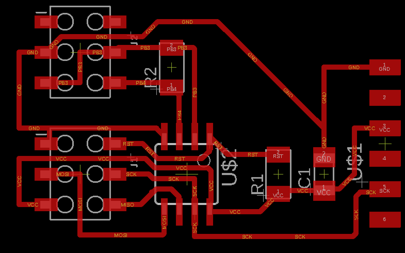
However, before milling it I realized that using capacitance touch for 132 countries would be a quite complicated job. Even if I divided the world map into smaller grids it would take time to solder everything. Doable yes, but very complicated to debug and I had exams coming up. However, the most problematic thing was that copper sheets are quite expensive and since I wanted my map to be quite big, I would have to pay a good amount of money for that. Because of this, I opted to change this project a little bit and now it would be interactive but instead of using touch, I would just use four buttons.
I then asked Anthony what microcontroller should I use and he recommended me to use the ESP 34 Wroof because it has more pins than the ATTINY and also more memory and other capabilities (like Bluetooth and Wifi). I want to improve my project during IAP to make it mostly wireless and so I thought that using this would be an actually great idea. I then looked for an example and thankfully Neil had one in the network and communications week. I then just added four buttons with their respective pull-up resistors to this board. The hard part was routing everything since initially, it seemed impossible to find an arrangement in which the paths didn't cross over each other but in the end, I was able to make everything fit.
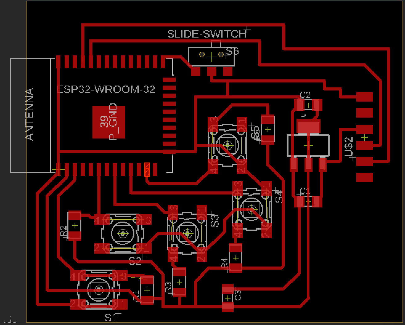

While adding the parts in Eagle I also realized that the library didn’t have the footprint of the ESP32 and so I had to download it from this website

When I finally finished the footprint of my board (this time I made sure to label all of the paths so that I could understand much easily the footprint when soldering and debugging) I saved the file in a USB flash drive and took it to The Othermill. I then opened it in the monitor but, after setting the tools to 1/32’’ and 1/64’’ the program was still telling me that the pads footprints of the ESP were too close together for the tools that I was using to do the job well. Because of this, I had to go back to my laptop and edit the footprint. I decreased the width of all the pin pads by quite a bit and then saved the file and returned to The Othermill.

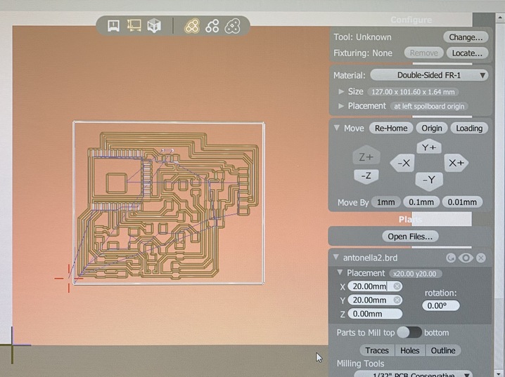

This time it said that everything was okay! I then proceeded to start milling it and voila! It was not too long that my board was ready to solder.
I made sure that we had every component that I was going to need:
The soldering process was slow but steady and the end result ended up looking pretty neat. In rder to soldering the ESP32 I used a hot air gun because the pins were super tiny, this was a very good idea. Overall, I was very happy with myself with how it turned out :)
Just in case, in order to avoid future complications when debugging, I made sure with a multimeter that all of the paths were correctly connected and that I didn’t have any shorts. All good! It was now time to program.


I saw Neil’s video and followed his instructions on how to set Arduino so that it is able to program the microcontroller. I first had to download the ESP32 board in Arduino by following the instructions of this website .
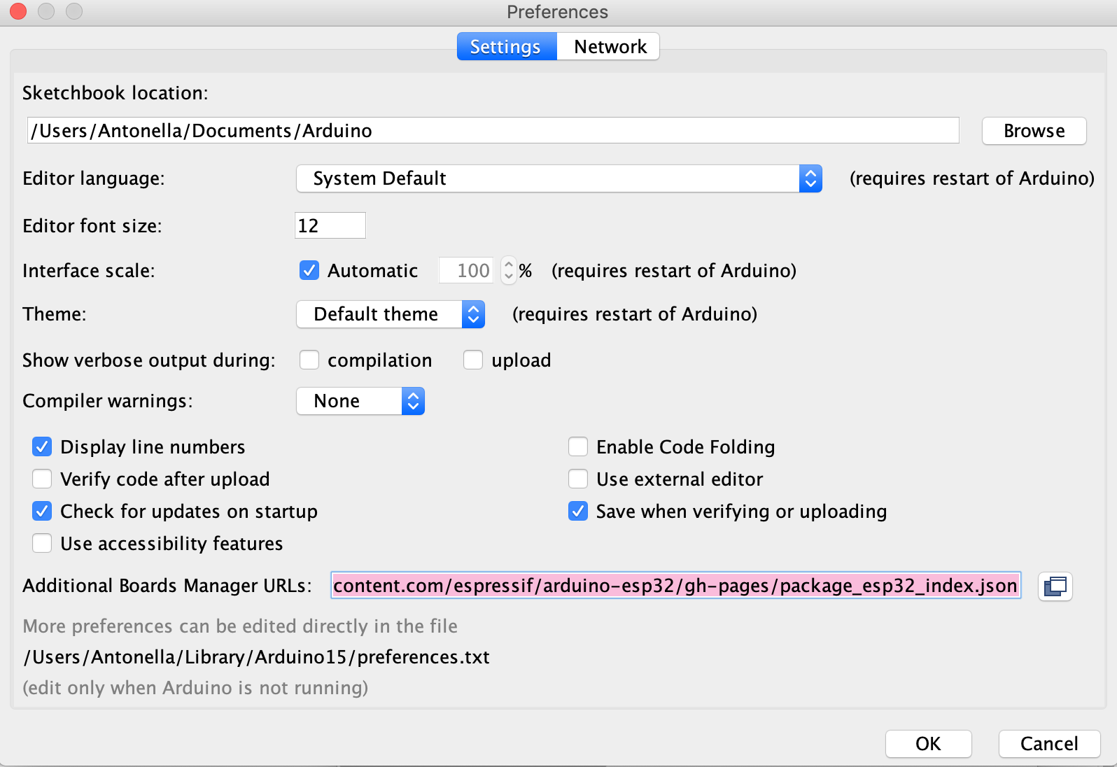
I then looked for a datasheet that would tell me the pin mapping of the ESP with the Arduino one and assigned their respective values to 4 different variables (the ones of the buttons). Finally, I wrote a small program that would output “a,b,c or d” in the terminal monitor whenever you pressed the respective button. Sadly, when I connected my board to my laptop using an FTDI to USB cable I realized that my Mac was not recognizing it as a serial port. This was weird since it, in fact, new that there was something connected to a port because I could see the port being occupied in my Utilities Tab. I tried to look for a solution and read this guide but even after installing their FTDI drive and uninstalling the one that mac comes with (which they strongly recommended me), it was still not working. Time was passing by fast and I needed to program my microcontroller and so I decided to use one of the PCs that are in the EDS. Thankfully, these ones did recognize it and so, after debugging my program, I was able to upload it and try it... IT WORKED!

However, I am still quite mad that my Mac cannot recognize the FTDI. Because of this, I'm planning to spend some of IAP trying to fix this issue. I will report any progress that I make here so stay tuned!
For networking week I decided to continue working on my final project. As I had decided, in the end, my final project would consist of a map with an integrated trivia game in which the player would be able to input their answers by pressing four buttons (a,b,c and d). I needed to find a way to send serial data to my computer so that I could use it as an input for my Python script. Initially, I was super confused because this was the very first time that I was doing something like this, but I was very excited to see the results. As I mentioned in my documentation for week 9, I was having issues with my Mac recognizing the FTDI to USB as serial port. This meant that, sadly, I couldn’t test my program from home so I spent quite a good amount of hours in the EDS and started to learn how to do serial communication.
After a little bit of browsing, I knew that I first had to download the package pyserial. I was using Anaconda --> Spyder and so I followed the instructions of this Reddit thread. What I really love of the programming community is that there are so many examples out there that one can use as a base for their projects and then just modify them according to your needs. Most things are also super well documented which makes it easier for beginners like me to understand what the program is doing. I hence followed this Arduino thread as a guide on how to read pushbuttons status with pyserial and started writing my program. I run into some issues and I must admit that I had to do quite a bunch of debugging (and spent a lot of time doing so). The first issue was that for some reason, even though the terminal monitor of the Arduino interphase showed a letter when the buttons were pressed, whenever I run the python program nothing was being recognized as an input. After writing some lines with print statements in order to determine where was it that the program was getting stuck I found out that I shouldn't put ".decode" after "ser.read" since, apparently, the letter that comes is already decoded in unicode.


The next problem that I encountered was that whenever I pressed a button, it seemed that the serial was being reading twice. This was more complicated to debug but after some hours of reading different threads and trying different things I figured out the solution. Apparently, the serial communication has a buffer and you always need to clear this buffer in order to avoid sending two (or multiple) values instead of just one. To fix this issue I had to write "ser.reset_input_buffer()" after and before reading it. I am still not entirely sure how this works but it made my program run so I just left it like that. I will probably look at this in more detail during the holidays because I'm quite curious on how serial communication exactly works.

After some other smaller bugs in my script I finally got my program to work!!!!! I was actually very proud of myself because I debugged it mostly everything on my own because Anthony and Alexandre were quite busy since the end of the semester was almost there and so they had to help a ton of people with their final projects.
Initially, just to debug, I had written the questions and answers in different arrays inside the python script. However, I want to continue this project in order to put it in the living room of my fraternity and so I wanted to have the chance of changing or adding new questions and answers easily. After a little bit of searching, I found out that a good option for this was by writing the questions with their respective options and answers in three different columns in an excel file. Then, I just needed to import xlrd and include the path to my excel document with all the data. It was actually pretty straight forward and I used this thread as a reference. As you can see in the following picture, column A=0 corresponds to the questions, column B=1 to the options and column C=2 to the correct answers.

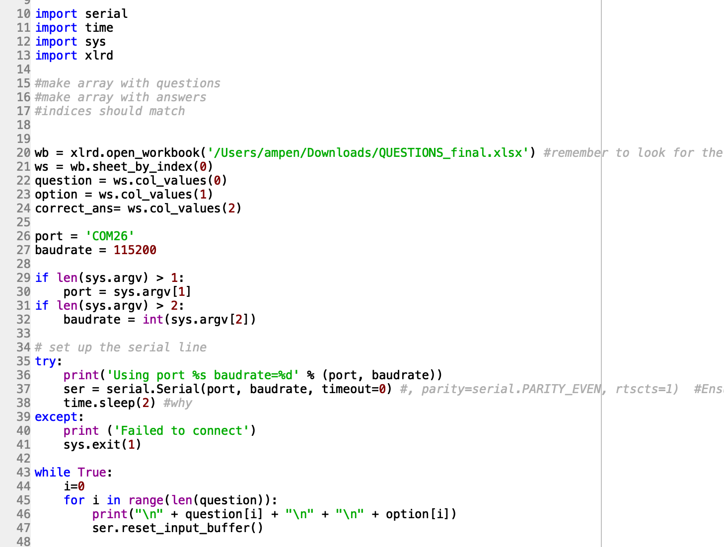


.
This week we had to create and design a website, learn about project management using Git and GitLab, make a constructive kit using a laser cutter and use the vinyl cutter to make a design of our choice. Phew. A. LOT. It was a hectic week, especially since I have no experience in making websites which is what ultimately caused me more trouble. In fact, I have been documenting my progress in google drive so far… that’s how far behind I am. This is a little intimidating but I try to see it as a great opportunity to learn a new skill that could be very useful in the future.
Me during the first lecture: *so… what is GIT?* Yikes, I started doubting if I was good enough to take this class. However, I soon learned that like me, there were other students who were also new to this “git” thing and so I started to learn. Since the days were passing by super quickly, I decided to start documenting my work in Google Drive so that when the time came and I was able to post something on my website, I would just need to cmd+c & cmd+v. Slowly, I started learning how useful Git is and I found the following instructions super helpful:
http://fab.cba.mit.edu/classes/863.19/doc/git/index.html
I then started learning about how to create a website. Every webpage on the internet uses:
So what do each of them do? HTML is in charge of defining all the web content, the text, the images, the links. CSS is responsible for the colors, font, and the positioning of content. CSS adds the styling to a website. It cannot live without HTML because then there would be nothing to style. Finally, JavaScript is in charge of all the pop air messages, the autocomplete tools. So as you can see, they need one another to make a complete and user friendly website.
For the design of my website, I used a Bootstrap template called Freelancer. I then proceeded to change the avatar so that it depicts me, and modified the design to personalize the website to my needs. Since I didn’t know CSS at all, and in order to save some time, I discovered that by right-clicking on my website and selecting “inspect”, I could hover my mouse on different sections of it and then I would be able to see the code that was involved to make it look the way it is. Then, with this information, I would just go into Visual Studio Code, my website editor, open the CSS folder and use cmd+F to find the section that I needed to change in order to make my website look the way I wanted. YAY TO SHORTCUTS!!


Let’s start with the Vinyl Cutter. I must admit that, initially, I was very skeptical about it. “It cuts stickers, fUnNnNn” -I thought. However, I then researched a little bit more about it and realized that the usefulness of the vinyl cutter is directly correlated with the ingenuity of the user. You can make shirt designs, use it as a template for painting, design circuit boards and even make clothes! It is also incredibly easy to use and does the job in very little time. I was exploring my options when suddenly I realized that it was already Monday and I needed to do something now.
My first idea was to vinyl cut a design and use it’s negative to print a drawing on a white shirt. Sadly, I was incredibly busy this week (and dedicated more time than what I would like to admit to the creation of my website) and so I didn’t have time to buy the materials needed or learn the art of how to do it. Instead, I decided to create a unique design by drawing something on my iPad and saving it as a PNG file. I ended up drawing a geometric fox with a quote by Thomas Paine, to remind me that some often overlooked and even degraded personality traits are, in many cases, the strength of the person.
The design part was fun and easy since I have been drawing digitally since I was 15. However, sticking the design to my door without damaging the details was extremely hard. It is worth mentioning that you need to choose your letter’s font carefully because yes, a font can look very pretty on your computer, but if it is too intricate you will probably end up ruining it when peeling off the vinyl. I had to try with three different fonts until finally, I found the one below which was thick enough to stay stuck on the surface and pretty enough (imo).
Important Facts:
-Use clear embossed tape roll for adhesive work
-Max distance is 24 x roll length
-Inkscape allows you to edit the image

For cutting the cardboard, we found that the Balsa wood setting was the closest to cardboard. However, we did find that the laser did not cut all the way through entirely. Upon our next trial, we lowered the speed from 16% to 13%. This allowed the laser to spend a longer amount of time passing through each point.
Joint clearance: joints need to be made to accept one another, but not be so loose to not stay together. We measured the thickness of the cardboard using a pair of calipers and got 4.3mm of thickness. In order to find the perfect fit we then designed a “test comb”: a long cardboard strip with rectangular cuts of varying width (going above and below 4.3mm). After various attempts, we settled on 4.00 mm as an ideal chamfered press-fit slot.
REMEMBER THESE
There are seven color options for the laser:
Settings:
I am a hyperactive person (I swear. I can’t even stay still in movie theatres so I have to sit next to the aisle to be able to stretch during the movie). Hence, I decided that it would be cool to make something that moves. I started thinking of different designs and then in my 2.005 class of thermal-fluids –in the midst of an extremely hot day– the idea came. Let’s do a fan!
I started designing the pieces in SolidWorks using a parametric design. In order to do this, I had to learn how to use the equations tab but when I was able to master this everything started flowing very easily. Thankfully, I had already worked with SolidWorks in the past so it was not as hard as I initially expected. I then proceeded to save my pieces as .svg files and started cutting them.


The fan was a little more tricky to design since it was going to be made using two gears and a ¼ inch (diameter) wooden rod. I played around with the parameters (this is when I realized how useful parametrization is in more complicated designs) and finally I did it. A wonderful fan made with cardboard!!!!!!!


During this week we learned how to do electronics production using a desktop milling machine. We built the FabTinyISP which is another version of an AVR ISP programmer/board. However, I was pretty confused about what I was actually making. Being a proud nerdy MIT student, I decided to investigate. This is what I learned:
When code is compiled into a windows program, it is turned into binary so it stops being human-readable and becomes machine-readable. Under windows, these programs (often called applications or executables) are often named ending with *.exe. On Macs, they are often named ending with *.App. For microcontrollers, binary files end in *.hex (short for Intel Hex Format). There are other formats possible, but this is the standard.
What I’m building is, as it has already been mentioned, another version of an AVR ISP programmer/board. But what on Earth is that? Well, apparently a programmer is a kind of electronic equipment that has the ability to configure integrated circuits which are both programmable and as non-volatile (they retain data even if there is a break in the power supply). My AVR ISP programmer will generate a .hex file from code, and will be able to transfer that *.hex program to a chip!

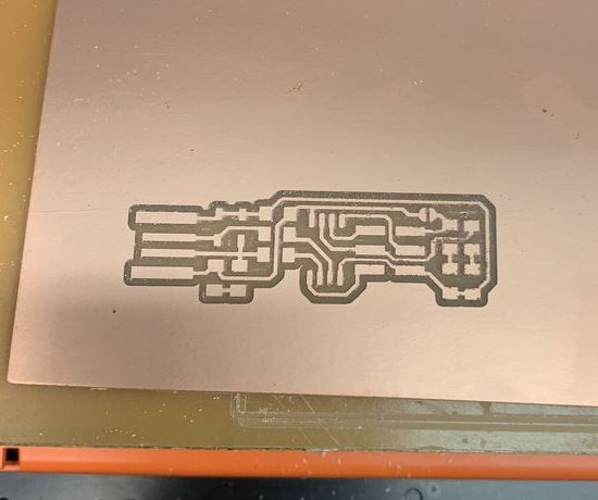

First, to make the PCB (which stands for Printed Circuit Board) we used a Roland SRM-20, a 3-axis CNC router with a 1/8" set screw collet that is controlled by a web browser program called mods –developed by the CBA. We used two kinds of tiny carbide end mills:
In order to see how thin the mill could go without sacrificing precision, we sent a test coupon to the machine. This consisted of test coupon traces and a test coupon outline
We then loaded the 1/64" mill, set the origin, zeroed the tool Z-axis and followed the mod’s recommended presets for routing traces. We then let the machine do its magic and repeated this same process but now with the 1/32" to cut out the test coupon. This is what we got:

We observed that the machine has incredible precision. When looking closely to the thinner cuts we noticed that they were a bit wobbly but overall the quality was pretty amazing and for what we were doing we didn’t really need to mill anything that thin so we were good to go.
I then uploaded the files needed for the PCB and in a few minutes, I had my PCB!!!!! I just needed to remove with a knife the copper in front of the pads.
Components needed


This is what you need when you start soldering. I had only soldered a couple of times before so seeing how smoothly Anthony did it and then comparing it with my wobbly attempts was not very encouraging. However, I did the best I could and I think it turned out alright. I learned a lot during the process though and that makes me pretty proud of myself. I noticed that there is a steep learning curve for this but once you kinda get the tricks then you start soldering faster and faster. I used a pair of tweezers to hold the components in place because they were actually very tiny and followed the instructions on this website to put everything in place.


I burned my finger a couple of times and squinted my eyes more than 100 times trying to find the component’s side with a tiny line that indicated which was the cathode side. However, after two hours of painful attempts, I finished soldering all the components.
Finally, I programmed my programmer and blew the reset fuse. Sadly, in the last step when trying to program another board something terrible happened…. The computer was not recognizing my programmer. OH NO!!! Let's see if you can find what is wrong in the next picture...


Anthony, Ben and I stayed an hour trying to decipher what the heck was going on until Ben realized that apparently, something had gone bad when milling my PCB and one trace that connected two components was missing! (You can actually see in the picture above, botton left of the PCB!) So I then used solder to make a bridge between these to components and BANG. It. Was. Working… and I could finally go to sleep hehe (BIG thanks to Ben and Antonhy, you both are my mental health’s savor). What a week!!!!
This week was very entertaining. I personally love 3D printers, especially seeing the process of how they build structures from nothing. When I still lived in peru I remember the day that 3D printers started emerging and I just couldn’t stop wishing to be able to use one someday. I can’t believe that now these machines are just a few meters away from my dorm! We also learned about scanning. I didn’t really love this part of the assignment because it was very hard to make the program work (it kept loosing the object and I had to go back and sometimes even start all over again). However, it was a great week still and I learned a lot about rapid prototyping and had a lot of fun working with my teammates and getting to know them a bit more, which I think is crucial since it will allow me to be able to work with them more efficiently in the future.
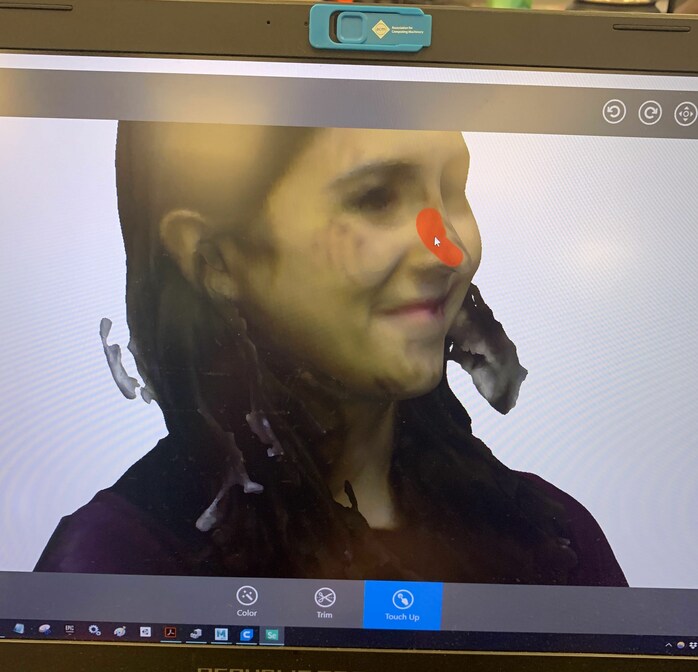
At first, I was ambitious and I wanted to scan my little Dobby. However, I soon learned that scanners (at least the one I used: Sense 3D) don’t work as great as I would have liked. They need a bigger object in order to avoid confusing it with the background. After several failed attempts I gave up and decided to scan something else… me! I asked Harrison (thank you Harrison!) to please scan my head. In my opinion, it made a decent job (if you try really hard not to think that I look like a character taken from The Walking Dead). You can see in the third picture how I tried fixing the hole in my nose with the tools that the Sense3D software provides, but there was no luck there either. Oh well, I like the Zombie-Anto version.
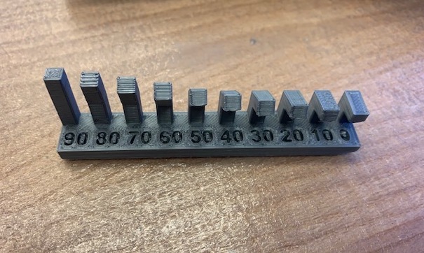
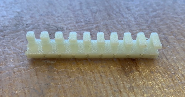
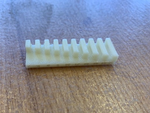
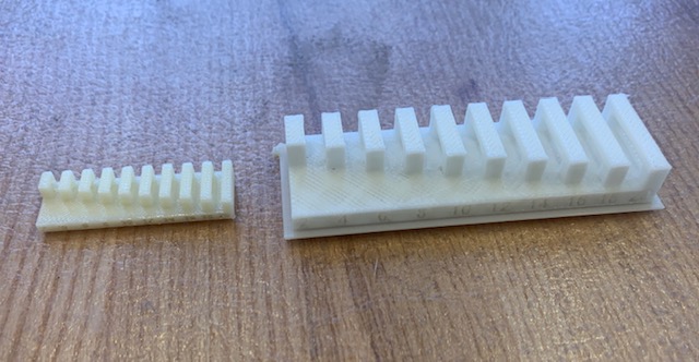
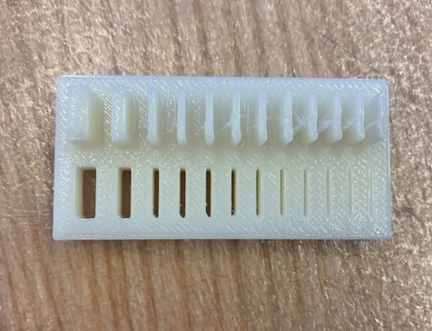
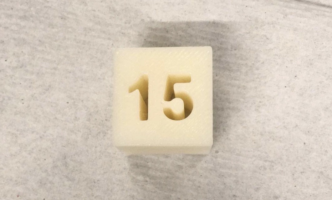
Apparently, there are four things that matter a lot when scanning objects/living things: These 4 tips will help you take better scans and probably keep you from stressing out in the middle of the afternoon when all you want to do is go home to rest for a bit and eat dinner… MY FAVORITE PART CAME! As usual, since it was our first time using a 3D printer in class we first needed to characterize our machine. To do this, my team and I printed a number of things to demonstrate what “additive” vs “subtractive” means, what infill looks like, what supported and unsupported overhangs look like, among several other types of objects. We were given stl’s for the following designs- we used the UPrint 3D printer and the Prusa, and divided and conquered the prints! Supports (overhang): This shows overhangs that were printed with supports. We didn’t have any problems when using supports. Supports (clearance): This shows the clearance of certain sized rings around a cylinder, allowing some to turn and some not. Unsupported –Angle: This is showing different angles of overhangs without using support material. It worked well at this size but it’s likely that it might not work with larger sizes. Unsupported –Free overhang: This shows unsupported overhangs- we didn’t use support for this one and it turned out well but again at larger sizes it might not work. Unsupported –Anchored overhang: First, we printed the free overhang *stl. using the Uprint printer. We scaled it down to save time and material We wanted to try printing without support material, and it worked well. We used the 3D Wox printer because we could select ‘no supports’ and print it freely. Here’s the two of them next to each other. We scaled the first one down but did the second one at 1.0x. Wall Thickness: This demonstrates different wall thicknesses- this is subtractive so it could be cut with a mill. Dimensions: We scaled this box down, it shows dimensions of two different boxes (the machine does a great job laying down plastic to make perfect squares). Anisotropy: This shows a 90-degree angle making the shape of an “L”. It’s a fairly small design so the upper part of the L stayed stable but if it was a bigger design it is possible the L would collapse without supports. Surface Finish: This is showing the outside and inside of a sphere and what the finish looks like. It almost looks like a perfect sphere- the machine is very accurate. Infill: This shows a box with the number fifteen cut- it could also be cut with a mill- it’s not additive. I was thinking about something to 3D print for a while that would follow the task requirements (an object that could only be made subtractively). After thinking for a while I decided to make a hollow mini rocket, where you can secretly hide tiny things or even a small message!!! I have always loved when products have hidden features so I thought that it would be cool to implement one myself. I got the idea of the rocket because they have a special meaning to me. When I was little I wanted to be an astronaut with all my heart. I think that I was set on that until I was about 15 years old and realized that I didn’t want to spend years alone in space, especially since I'm so hyperactive. However, rockets always remained as a symbol for me that if you put a lot of effort into something you can go anywhere you want. Nothing can stop you, only your determination. I even got a rocket tattoo on my wrist when I turned 17! To remind me to never stop fighting for my dreams. For me, it was going to MIT… I still can’t believe this is all true. STEPS TO PRINT: I decided to use SolidWorks to design my rocket. However, I first sketched a couple of different rocket styles, looking back at my rocket tattoo for inspiration of course, and finally ended up with a concept that I really liked. Then, I started sketching one of the rocket’s smaller engines and then the main body of the rocket. Something that caused me some trouble was the fact that I wanted to make a dome shape but, at first glance, it didn't seem that SolidWorks had that option. However, after I asked the great oracle Google, I found out that there are lots of more features hidden under the insert tab!!!! I used the circular pattern tool to triplicate the smaller engines so that I didn’t have to design them all over again from scratch. Finally, I cut extrude two circular windows and then, using the transparent view that SolidWorks offer, I was able to look inside the rocket and cut extrude a tube inside it (this will be the “secret chamber” to hide things hehe).
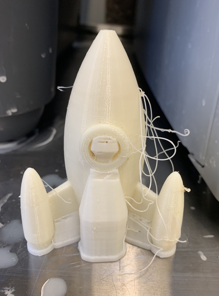
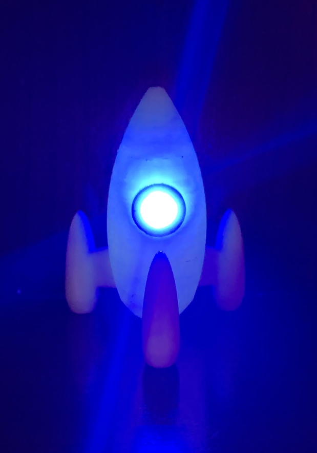
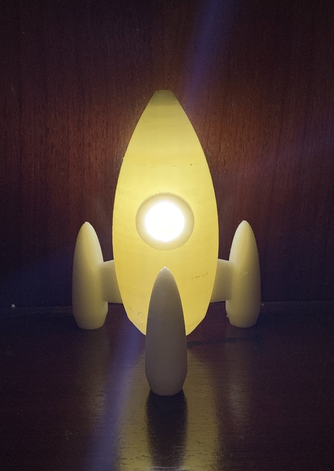
And finally Something that worries me is that I still haven’t been able to print it because I have been incredibly sick last week and could barely get out of bed. I’m going today to 3D print it… fingers crossed that everything will turn out okay!! So the next day of writing the previous paragraph I went to the EECS shop to 3D print my rocket. I was a bit nervous because I had mixed the dimensions in solidworks and instead of using inches I had been using mm without noticing and so I needed to scale my whole rocket because I want it to be bigger. Thankfully, Anthony showed me that the Uprint's interfase allows me to scale my files. After uploading my dxf file to the pc connected to the 3D printer, changing the settings so that they met my needs I started printing. It was going to take approximately 6 hours and so I returned the next day to take it out. It looked pretty well! But it still had some supporting material. Something really interesting about the Uprinter is that it is able to print complex structures thanks to the fact that it incorportates a material for support so that after 3D printing your design, you can just put it in a special hot bath that dissolves the supporting material after a few hours. The suppoting material is mainly used when you want to 3D print something that could melt while being buil due to the force of gravity (such as a 90 degree beam or something spherical). The following picture shows how my little rocket looked before the bath. I was super happy with the results and took my rocket to my frat. However, I really prefer things that have a purpose and my little rocket didn't seem to have any purpose in particular. While I was studying for my 3.091 chemistry test on the topic of photons and electrons I realized that I could place one LED light inside and use it as a lamp!!!!! I tried with different colors and finally decided to change the color of the LED according to my mood. Here are some pics of the final product... Which color do you like the most? 

3D PRINTER CHARACTERIZATION





3D PRINTING IDEA

DESIGN

3D PRINTING



This was an intense week. We had to redraw the ATtiny 44 Echo Hello World board using the Eagle program and add a button with a 10K resistor and an LED with its current-limiting resistor. However, we were also asked to design in CAD our project for the “Make Something BIG” week since my section (EECS) was going to have to use the architecture shop too and so we needed to be as efficient as possible with time. In addition, I have my 2.005 Thermal Fluids Exam on Monday so I think that I will be destroyed by the end of Wednesday but hey, a long weekend is coming!
ASSIGNMENT
On Friday I came to the EDS shop because I was incredibly confused with how to use Eagle. Sadly, Anthony wasn't there yet so I started watching an Eagle tutorial which turned out to be pretty handy. First, I downloaded the fab library with all the components that we were going to need and imported it to Eagle by copying and pasting the path. Then, I started adding all the components. We needed:
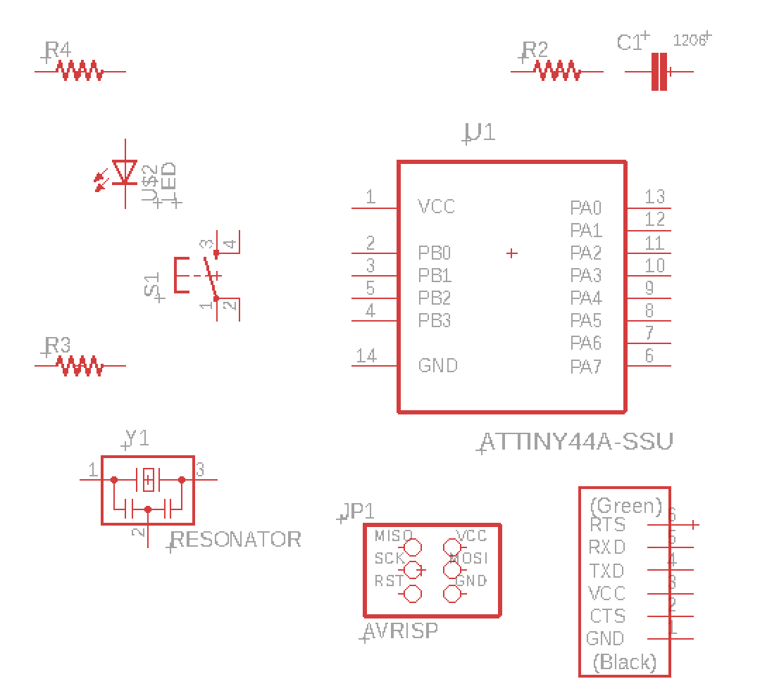
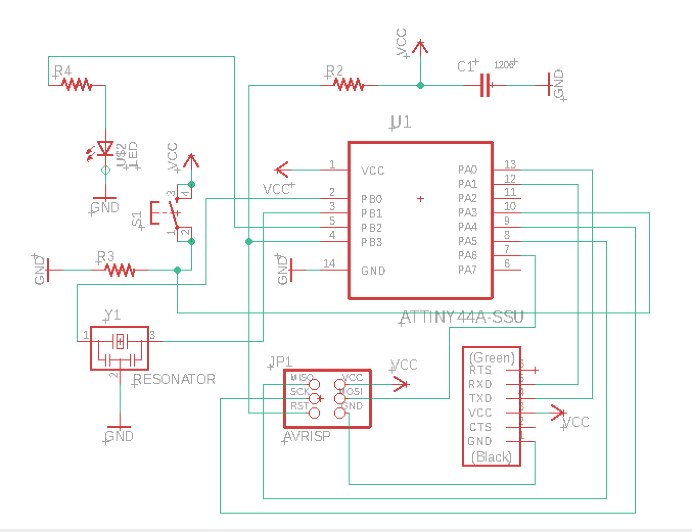
It was also important to follow the design rules: use traces of size 12 in order to be able to solder it later, if not it would be too small. I also tried to keep my shcematic as clean as possible by adding a ground symbol and connecting the components to this (to avoid having a labyrinth of net lines going to ground). I did the same for the voltage supply VCC. Overall, I must admit that it was a bit difficult to understand how Eagle works but after a while I started getting used to it and everything started flowing more quickly. Something that I realized is that I need to learn more about circuits and electronics. I am hoping to use this IAP to explore this branch a bit more.
After finishing my schematics and getting Anthony’s approval, I began doing my board layout. It was VERY hard to make all the components fit nicely (although also weirdly satisfying) but finally, I manage to get everything on the board. Something that I learned is that when you have more components it gets increasingly difficult to make everything fit in the board. In order to solve this issue, Eagle allows you to do some “tricks” like working with different layers. If you do this, you could make one of your layers be ground and then just connecting the ground of your different components with this second layer. By doing so, you would greatly reduce the number of traces in your top layer!
Here are the steps that one should follow when making a board:
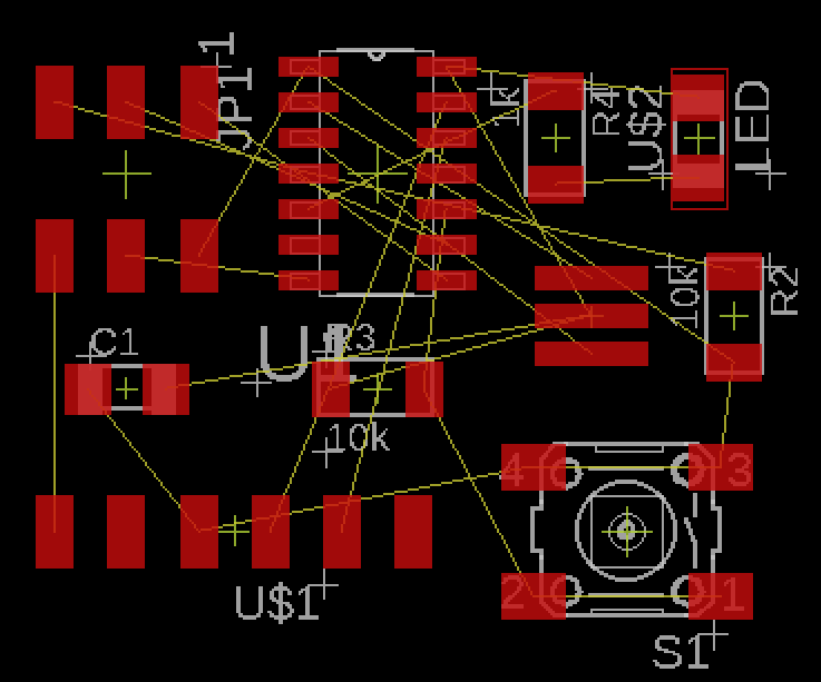

Once I was done with my board layout, I was ready to start milling it. The EECS shop has two different milling machines. I had used the Roland to make my programer back in week 3 so I decided to use the OtherMiller this time to get a sense of how these two machines work. There were some differences (like the format in which you need to export the design. In Roland you need to export it as a monochrome png but for the OtherMiller you just need to export it as an Eagle format.
For Roland:
For OtherMiller:
Time to mill! I just connected my USB with the monitor connected to the OtherMiller machine. Typed the correct settings (I used a 1/64" tiny carbide end mills for routing traces and 1/32" for cutting out the finished board) and started the machine. Easy peasy :)

Here is the fun part: soldering. The components I used were:
It was pretty hard to solder everything together. The components were SMOL and it was quite hard to follow the board schematics. For the ATtiny44 and the resonator I used the soldering paste and the hot air gun. It was pretty simple and I ended up loving it since it soldered the components to the board very nicely and easily. I finished soldering and then I realized that I had put my ATtiny44 upside down because instead of following the board plan on my computer, I looked at the schematics set up and of course the position was not correct so I had to desolder it, turn it, and solder it again.


After a few hours of hard work, I finished soldering! –or that’s what I thought. I then connected my board to the EDS shop Linux pc but… OH NO! It was not recognizing my ATtiny. I was sad, very sad. I asked Ben for help and he kindly helped me check what was going on with the use of a multimeter. So first, we found out that one of the pins of the 2x3 header was not well connected and so I soldered it again. However, it was still not working. Then we realized that there was a bridge connecting to paths that were not supposed to be connected but after a good eye scanning test we couldn’t find a point where I had accidentally bridged to paths with the solder. Conclusion: the bridge was probably under the microcontroller. I had to desolder that once again, clean the part, and solder it again. I then returned, praying that it would please please work… AND IT DID!!!!!! Now it was time to program it!


I saved all the Hello World Echo 44 files from here. I also downloaded the “term.py” file from the same site. Just use Ctrl + F and type in term.py.
I used the EDS shop’s Linux PC to do all the programming following the guide. First, I connected my ATtiny45 ISP (programmer) from week 3 to my ATtiny44 Hello World board (target) using the ISP headers. Then I connected the FTDI (USB cable) to give my ATtiny44 (target board) power.


After connecting everything, I ran my VM and did the programming. First, I had to cd into the directory where I saved the files. Then, following the guide I typed: make -f hello.ftdi.44.echo.c.make and sudo make -f hello.ftdi.44.echo.c.make program-usbtiny-fuses I was using the USBtiny board to program my ATtiny44. However, if you do cat hello.ftdi.44.echo.c.make you will see that there is an option for ATMEL ICE programmer and AVR ISP as well.
After all the setup and programming into the target board ATtiny44, it is time to test the ECHO! Now I typed sudo python term.py /dev/ttyUSB0 115200 and a new screen should pop-up and you can type letters or words in it and it should ECHO back.
IT WORKSSSSSSSSS!!!!!!
For this week, we were given a 4'x8' sheet of OSB and were asked to design something BIG that could be made out of OSB (oriented strand board). We were free to do whatever we wished which was actually very exciting but at the same time quite difficult. I spent a considerable amount of time trying to think about something that I needed and could be done with this material. It was also difficult to deal with the properties of OSB. This material is very flaky and not good for thin features since it snaps, so I had to avoid structures that would need this kind of measurements. On the positive side, OSB is very cheap which is why it can be quite convenient at some times.
After throwing some ideas and looking at some people’s past projects I decided to make a standing desk. Something that most people don’t know about me is that I suffer from quite severe ADHD. I take pills daily that help me combat this but it can get pretty rough. Something that helps me a lot is doing exercise but sometimes MIT, being MIT, doesn’t let me have enough time in my schedule to go to the gym. During these times, which normally coincide when I have to study for midterms, I get incredibly stressed. I also find it super hard to sit for long periods of time –which is why I have to sit next to the aisle when I go to movie theatres… and why this class’s lectures are particularly hard for me lol. My solution so far when I really can’t stand sitting any longer but I still need to do PSETs or study has been to kneel down. To be honest, it looks pretty funny so I normally only do this when I’m in my room (I even bought a special cushioning pad so that my knees don’t get sored! It is because of this that I decided to make a convertible standing desk.
I used SolidWorks to design the parts. I wanted to make a standing desk that you could adjust to your height and so I decided to include 11 joints so that you could adjust the “table” to your needs. I also decided to make 2 tables instead of only one to give more space to the user. While making it, I realize that it would be useful to add a slit in the lower table so that you could slice the power cord of your laptop through it. I also wanted it to be portable. I am aware that OSB can be pretty heavy but I wanted to make a prototype now so that in the future I could perhaps do a second version of this portable standing desk but with a different material (like plastic).

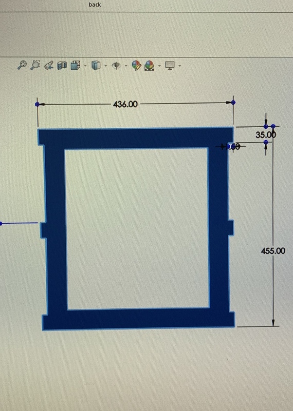


Designing this standing desk was one of the most difficult parts was the designing process since I was doing it from scratch.
This was a long weekend and I had already bought my tickets to go to New York from Friday to Monday. Sadly, that meant that I didn’t have access to a computer that enabled me to use SolidWorks (the CAD software that I feel more comfortable using). I tried downloading VMware but when I tried using SolidWorks using the virtual machine it just kept crushing. Hence, my only option was to finish the CAD design before leaving… STRESS. I stayed up all Thursday night until 4am on Friday trying to finish it. I was almost done and sent my SolidWorks parts files to Anthony so that he can give them a look. He noticed that some parts had the wrong dimensions and were not fitting quite well and also told me to increase the width of some of the features so that they were closer to the 2’’ mark (in order to avoid the OSB to crack). I had initially made a quite interesting design for the desk but sadly I had to discard it because of the limitations of OSB. While in NY I was able to find a PC in my friend’s office that had SolidWorks installed and so I used it to tweak the design a little bit more. I’m glad I did this because my Greyhound bus got 3 hours delayed. In addition, due to the traffic, the trip ended up lasting 7 hours and so I arrived in Boston on Tuesday afternoon instead of Monday night.
I then rushed to the arch shop and, thankfully, Anthony was there (PS: If you read this Anthony I'm so sorry for arriving so late. I really appreciate the time that you took to help me finish my standing desk and how patient you were with me). He kindly reviewed my design once again and noticed that the only thing that was wrong was that when I had made a linear pattern for the obstructed cut for the joints of the back, I had put 176cm of separation (the distance from the lower edge of one slot to the upper edge of the slot below it) instead of 206cm (the distance from the lower edge of one slot to the lower edge of the slot below it). See the picture below for reference.
After fixing this, we laid down all of the components flat on one plane (making them fit in the 4'x8' sheet) so that they could be cut by the machine. Next, I had to create toolpaths in masterCAM for the parts. I exported the SolidWorks assembly as a part and then as a .dxf and imported that into masterCAM. First, I made sure to align my parts with the origin and that the material was on the left of the mill when cutting- which is climb vs conventional milling.
At first, there were some strange u shaped cuts on the edges of my design and it’s because masterCAM used lead-in and lead-outs to cut the material. In my case, since we were using OSB, we didn’t need them, but if it were metal it would be important because the mill is not meant to cut straight into the metal but rather spiral in.

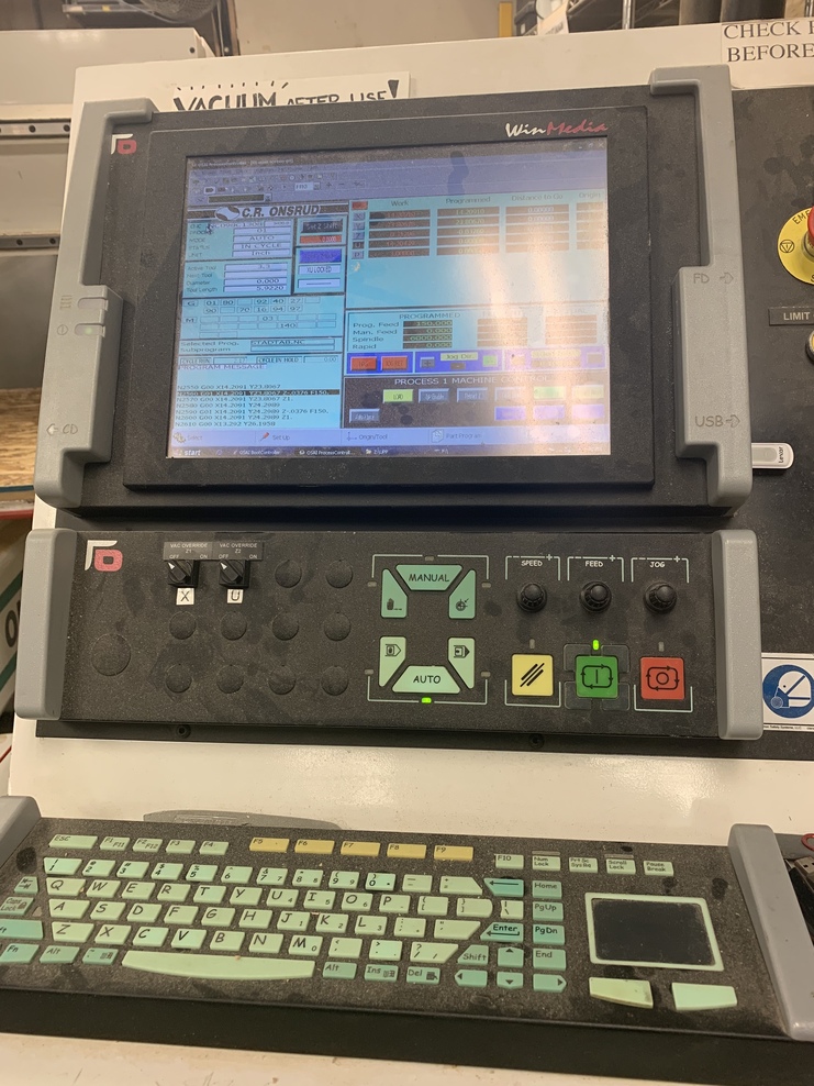
Using a USB, I took my files to the Onsrud machine’s interface and then cut the OSB (the machine is HUGEEEEE). There’s a hard stop and a soft stop- soft stop will save the current job and continue but hard stop will stop all processes and forget everything- important for emergencies. Before running the machine, I had to turn on the valves which using suction held the OSB material to the surface of the machine.
After the job was done (took only like 6 minutes!) I had to use a boxcutter to cut the last thin layer of OSB that was still there because I used the onion skin option in order to get more accurate cuts, especially for the slots. The OSB was pretty difficult to cut with a box cutter cleanly so I had to do a lot of filing to clean it up. I really don’t like OSB.
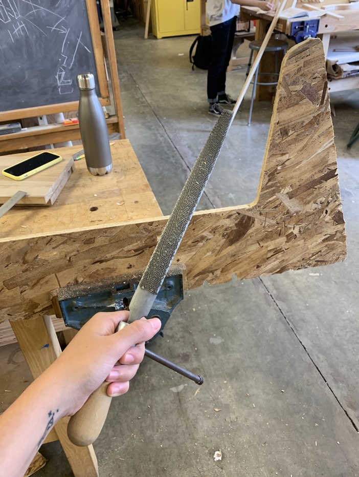
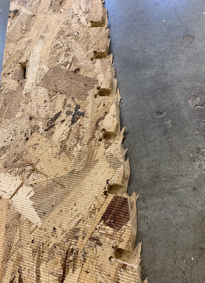


This was my very first time designing something from scratch in such a short amount of time so I had some slight mistakes in my design. Some of the things that I could improve for the next version is to increase the width of the large sloths of the two “tables” so that they can go up and down and adjust to the user’s height more easily. I would also reduce the width of the slots in the sides to get a better press fit joint. Mine ended up being too big (maybe also because of the OSB since when filing it, it kept breaking apart) and so it was not tight at all. However, despite the mistakes, it turned out quite nicely though! You can use the 11 different levels to adjust the tables to your height and be super comfortable. I am going to try to find time now to sand it in order to make it feel more like real wood and stain it. I’ll update this page if I get to make any improvements!


This week’s assignment was to try different languages and programming environments to program the board that I built on week 4 and make it do something. First I read the ATtiny microcontroller datasheet in order to understand how it works. I had quite a lot of trouble making sense of the data sheet though, because it had a lot of information and I’m fairly new to electronics –I had played around with them before but without really understanding what was going on in the lower level.
Because of this, I decided to start programming in one of the easiest ways: Arduino. I have used Arduino boards before so I was curious to know what would be the pros and cons of using a regular Arduino board with an ATmega328P vs using my DIY board with an ATtiny 44A. This is what I found out
Cons of using an ATtiny vs ATmega:
ATtiny 44A |
ATmega328P |
|
Fewer pins: you can’t connect as many components |
More Expensive |
|
Less flash memory (4KB or 8KB instead of 32KB): your programs can’t be as big |
Bigger and bulkier |
|
Less RAM memory (256 or 512 bytes instead of 2KB): |
(In the Arduino board), can’t customize board to needs since all the components and the shape of the board have already been set. |
|
No hardware serial port or I2C port (Wire library), making communication trickier. |
In conclusion, since I was doing something fairly simple for this week (mainly just getting familiar with microcontrollers and how to program them) it was perfectly fine for me to use ATtiny. However, if I wanted to hook up more components or do more complex communication or data processing, I would have to use something like the ATmega328P.
I already had the Arduino software installed on my laptop so I only updated it by downloading the new version from their website. I then had to download the ATtiny support to let Arduino know which analog pins belong to which digital pins. These are the steps I followed:
In Arduino 1.6.4, you can install the ATtiny support using the built-in boards manager.

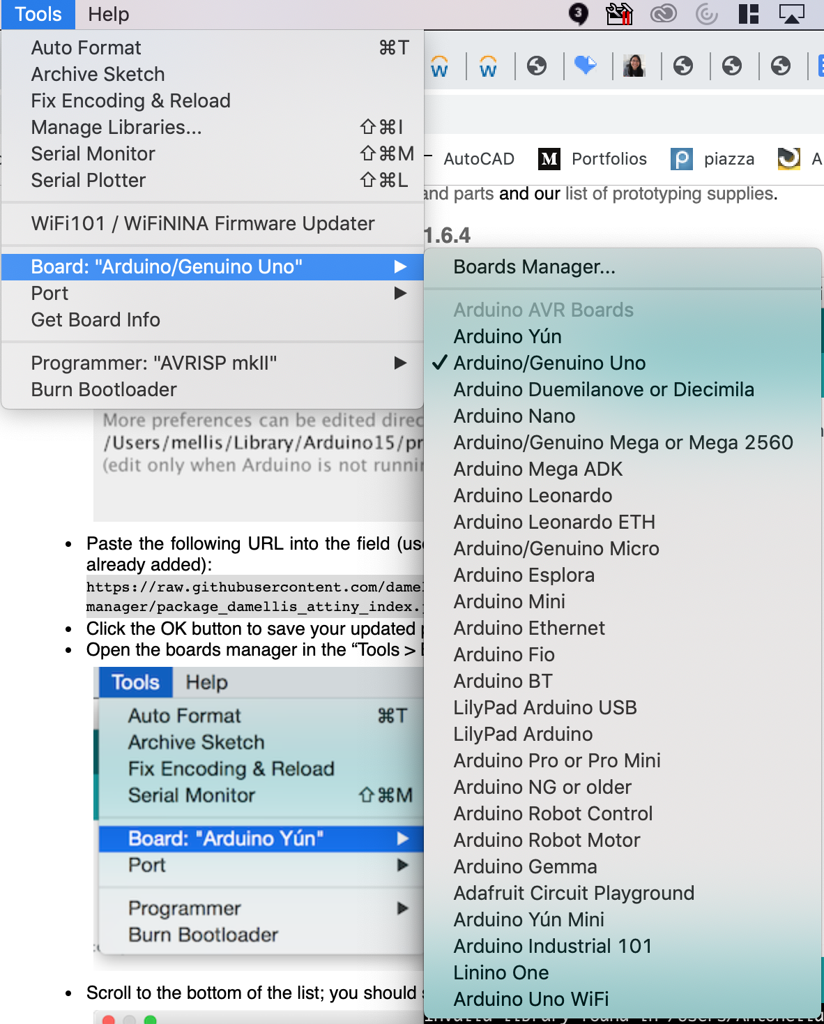

Done!!! I used this website that guided me through the process.
It has been a while since I used an Arduino and to be honest I never truly understood how to program in them from scratch (I usually just copy codes and modified them so that they did what I wanted them to do). Because of this, I decided to use this week to truly learn how to program using Arduino using C. Sadly, MIT knocked me again I ended up barely having time to do the basic rquirements for this week's assignments :(. I will try to use the following weeks and the process of building my final project to learn more about embedded programming. For now, I just focused on making my light turn on and off with the press of the button.
Something that I learned was that I needed to look for the conversion between the actual pins of the ATtiny and the digital pins in the Arduino. To do that, I used the data sheet that I had to look for the text file with the relation between them:
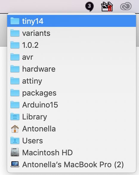
This can be found by going to the Arduino folder --> Packages --> attiny --> hardware --> avr --> 1.0.2 --> variants ---> tiny14.
So as an example, my LED was connected to the ATtiny pin 5 (as you can see in my footprint schematic below) which according to the data sheet is called PB2. Then, using the text file with the conversion I knew that I should declare my variable for LEDpin = 8.


With the pins already mapped, it was pretty straight forward to make the code.
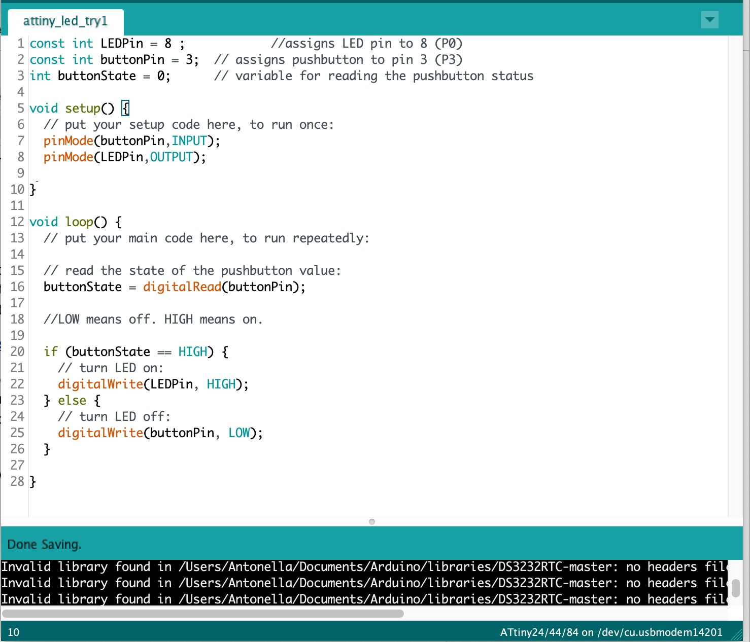
Let’s see if this works! I took my board to the EDS shop PC (since I have a Mac and Ben told us that it would be trickier to do it from our laptops). I needed to provide power to the ATtiny and connect it to my programmer. That is, connecting MISO, MOSI, SCK, RESET, VCC, and GND of the programmer to the corresponding pins on the ATtiny.
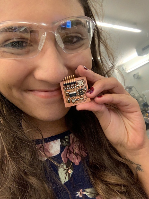
After doing all the connections I uploaded the program and…. It worked!!!!!!! Look how happy I am!!!!
For this week we needed to design a mold and use it to cast parts. I thought that this was going to be quite easy but I was completely mistaken… mostly because I didn’t initially quite understand what making a mold meant.
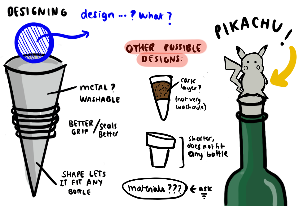
This week seemed a cool week to experiment with different things and create something cool. It didn’t take me long to realize that I really wanted to make a wine plug. I really like wine, and I enjoy to drink one glass every few days while PSetting. However, I have this problem that sometimes I can’t put the cork back and so I need to either:
But, as you can see in the following graph, none of these make Anto happy:

Because of this, I decided that it was time for a change and I decided to make a wine bottle plug. I also reallyreallyreaaaaaally like Pokemon and so I decided to put a Pikachu on top as a decoration (yay to the geek fam!). Initially, I wanted to use metal for casting but sadly, I soon realized that the materials we would be using to cast it (even the metal since we would be using an alloy with a low melting point) might not be very food-safe. Some possible solutions for this were either purchasing some of the food-safe materials from Smooth-On or look into plating the outside with a food-safe metal. However, time flew again and I didn’t have time to research more about this so my wine bottle plug will be, for now, just a proof of concept. Sad.
I used SolidWorks again to make the design. This is when I ran into some issues. The first problem was that I didn’t realize that we were doing a 3 step molding-casting process (positive to negative to positive). Because of this, I started designing a negative for my piece using a free stl of a wine bottle plug I found online. I spent a long time modifying the file to fit what I have been picturing but then Anthony made me realize that this was not what I was supposed to be CADding since it was the positive of the part. In order to fix it, I had to use the SolidWorks function of extrusion, to make a block that would encapsulate the negative (without merging them so that I would have 2 separate bodies). Then, I had to go to insert → features → combine bodies and in here use the “subtract” option, selecting the extruded cut as the feature to subtract from the main body (the block).
My other issue came up when I was designing Pikachu. I somehow was designing it thinking as if a 3Dprinter would make it -stupid brain- so I downloaded a free stl that I found online and modified it a little bit.
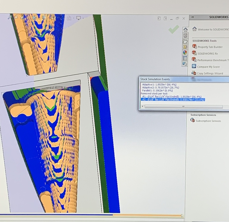
Because of all the confusion with the CADding, it took me a while to finish this and so I must admit that I went late to the shop to make the mold (yes, I agree. This shouldn't happen. Please roast me.). As expected, there were a lot of students there and so it was even harder for me since I have a mac and so I cannot run SolidWorks in my computer so my only option was to wait for the EDS PC with SolidWorks installed to be free. This took some of my time and then, in addition to this, when trying to run it in CAM and set the toolpaths there were some issues with the shape of my part since it had a hellix pattern. Thankfully, Anthony helped me figure things out and we finally ended up with what we thought would be the best tool paths for my design. I used a step down of 0.4 for the larger mill and 0.2 for the smaller mill, did another adaptive (tricoidal: gives you a faster removal of material rate) milling with the 1/8 inch mill and used a cut rate of 100rpm and made sure that we are not cutting things that have alrready been removed. I also learned that the blue lines is where it is actually machining, green is lead ins and lead outs, and yellow are rapid moves. I still don't feel very comfortable in computer-aided manufacturing. I lack the intuition and expertise of choosing the right tools, the right paths, etc. However, I do feel that I have learned quite a lot in the process, but I still have a long way to go. Here are some important points that I learned during the process: The EECS section used the shark machine because we needed to use a 6 x 6 inch piece of wax and neither the othermill or the rolland are able to fit an object of that size.
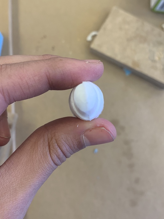
I used the shark touch plate to set the z-axis: the machine brings the mill bit down until it touches the plate. It is actually pretty convenient since the machine knows the width of the plate and I don't have to almost any setup for this. By doing so, the machine figures out exactly where the material is. The mold ended up turning out pretty great! It was now time to start doing the mold. To measure oomoo ratios I just poured water in my wax positive part to measure how much volume I need of liquid and then pour that water volume into a cup, split it in half and then mark where those volumes were. Then, I poured parts A and B respectively into those cups, mixed for a good amount of time (approx 4min each) and then pour both mixtures togethers in one same cup and mix again for about 4minutes. It is very important to mix everything well while at the same time try to avoid creating lots of bubbles. Finally, I poured the mixture into my wax and waiting for it to dry. It took about 4 hours to completely dry. After it was completely dry, I pulled the mold out of the wax trying to not break it. I used a wooden stick to help me get it out. It looked pretty good... However, I soon realized that it was going to be hard to pour the liquid plastic that I was going to use to make my piece. This was because, due to the size of the wax, I was not able to fit my two parts in a way that there was enough space to make one fit into the other one which is by far the best way to do this in order to avoid your piece to get deformed when drying. Here is a diagram that I made illustrating what I mean with this. With the design above, you would only need a pair of G-clamps in order to constrict all the degrees of freedom. However, because of a lack of material, I couldn't do that. I also thought about making press fit joints when cadding my part and initially I actually had them but for some reason when I was setting the tools and paths, a weird issue kept happening in which the whole positive wax mold ended up getting ruined. Due to a lack of time to fix this problem, Anthony adviced me to delete those press-fit joints. This is the reason why I had to use a lot of creativity in order to somehow make a structure that would be able to hold all of the liquid plastic inside the negative mold. Behold my life's creativity peak: After about 100 trial and errors, I managed to make this structure that made the molds fit tight enough to hold the liquid plastic without drippings. But as you will see below, there were some problems with this techinque. Since my molds were flexible molds, whenever I squish them together their shape changed. This meant that my final piece came out a little bit squished from one diameter. This is specially noticeable as you look closer to the thinner end (left picture below) since that was one of the critical points from which the liquid plastic would drip -due tu gravity- if there was nothing squiching the two molds tightly together. For a first try, I think that it turned out pretty okay. I was sad though because I tried to test it in a wine bottle but it was a little bit smaller than what I had planned. If I ever attempt to make a wine stopper like this in the future I will deffinitely scale up my CAD design. I would also make the molds in a way that just by placing the two parts together, all the degrees of freedom would be constricted and, last but not least,I would use a food safe material. I decided not to not continue to 3D print the Pikachu because of a lack of time, and since this was just a proof of concept that had some size issues, it would be quite pointless to invest more time in it. However, I learned a lot! And now I am much more open to the idea of using molds to create objects instead of only relying on the 3D printing. 

CAM

MACHINING

MOLDING



Days were passing by quickly and I started worrying about my final project. The initial idea was to make a touch-sensitive interactive map. Because of this, I wanted to learn more about step response and so I started following Neil’s board and making my own in Eagle.


However, before milling it I realized that using capacitance touch for 132 countries would be a quite complicated job. Even if I divided the world map into smaller grids it would take time to solder everything. Doable yes, but very complicated to debug and I had exams coming up. However, the most problematic thing was that copper sheets are quite expensive and since I wanted my map to be quite big, I would have to pay a good amount of money for that. Because of this, I opted to change this project a little bit and now it would be interactive but instead of using touch, I would just use four buttons.
I then asked Anthony what microcontroller should I use and he recommended me to use the ESP 34 Wroof because it has more pins than the ATTINY and also more memory and other capabilities (like Bluetooth and Wifi). I want to improve my project during IAP to make it mostly wireless and so I thought that using this would be an actually great idea. I then looked for an example and thankfully Neil had one in the network and communications week. I then just added four buttons with their respective pull-up resistors to this board. The hard part was routing everything since initially, it seemed impossible to find an arrangement in which the paths didn't cross over each other but in the end, I was able to make everything fit.


While adding the parts in Eagle I also realized that the library didn’t have the footprint of the ESP32 and so I had to download it from this website

When I finally finished the footprint of my board (this time I made sure to label all of the paths so that I could understand much easily the footprint when soldering and debugging) I saved the file in a USB flash drive and took it to The Othermill. I then opened it in the monitor but, after setting the tools to 1/32’’ and 1/64’’ the program was still telling me that the pads footprints of the ESP were too close together for the tools that I was using to do the job well. Because of this, I had to go back to my laptop and edit the footprint. I decreased the width of all the pin pads by quite a bit and then saved the file and returned to The Othermill.


This time it said that everything was okay! I then proceeded to start milling it and voila! It was not too long that my board was ready to solder.
I made sure that we had every component that I was going to need:
The soldering process was slow but steady and the end result ended up looking pretty neat. In rder to soldering the ESP32 I used a hot air gun because the pins were super tiny, this was a very good idea. Overall, I was very happy with myself with how it turned out :)
Just in case, in order to avoid future complications when debugging, I made sure with a multimeter that all of the paths were correctly connected and that I didn’t have any shorts. All good! It was now time to program.


I saw Neil’s video and followed his instructions on how to set Arduino so that it is able to program the microcontroller. I first had to download the ESP32 board in Arduino by following the instructions of this website .

I then looked for a datasheet that would tell me the pin mapping of the ESP with the Arduino one and assigned their respective values to 4 different variables (the ones of the buttons). Finally, I wrote a small program that would output “a,b,c or d” in the terminal monitor whenever you pressed the respective button. Sadly, when I connected my board to my laptop using an FTDI to USB cable I realized that my Mac was not recognizing it as a serial port. This was weird since it, in fact, new that there was something connected to a port because I could see the port being occupied in my Utilities Tab. I tried to look for a solution and read this guide but even after installing their FTDI drive and uninstalling the one that mac comes with (which they strongly recommended me), it was still not working. Time was passing by fast and I needed to program my microcontroller and so I decided to use one of the PCs that are in the EDS. Thankfully, these ones did recognize it and so, after debugging my program, I was able to upload it and try it... IT WORKED!

However, I am still quite mad that my Mac cannot recognize the FTDI. Because of this, I'm planning to spend some of IAP trying to fix this issue. I will report any progress that I make here so stay tuned!
Now that a few weeks have past and after several conversations with my TAs, I am much more in track with what my final project will be. For this week, I will make a simple board for an OLED screen in order to understand how circuits work.
In order to make the schematics I used Neil’s footprint as a guide.

I started making the Eagle schematic and footprint but then I realized that I could not find a footprint for a 1x4 female heather in the fab or eagle libraries, which I needed to connect the OLED to the board. Because of this, I decided to make my own footprint. It was a bit confusing in the beginning but even though it took me a while, I finally did it. First, I looked in Digikey for the exact dimensions. However, when I look for female headers I found out that there were millions of options so I had to visit the fab inventory first and from there find the piece that I was looking for and then copy its name code in Digikey.
I then opened its datasheet and wrote down the dimensions that I needed.
Then, in Eagle’s control panel, I clicked on File → New → Library
In there I did the schematics symbol. Then, I made the footprint which was quite harder since I had to get the exact dimensions in order to make everything fit exactly while soldering. I had to first input the dimensions of the pads (0.079 x 0.039 in) and then a very good piece of advice that Anthony gave me was to set the grid width to a multiple of the width of the pads in the datasheet in order to decrease the chances of getting the dimensions wrong.
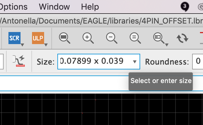

Finally, I finished my footprint with some hicups in the way (for example, I initially got confused with the number of pins shown in the schematic and the ones shown in the footprint. Since the 1x4 pin header that I designed was actually 4 alternating pads, that made me get the number of pins wrong on the first try. However, after some debugging, I finally understood what was going on and got the connections in the right order. I then saved my footprint and milled it in the Other Mill. However, I also wanted to learn how to use the mill that's closer to the left of the lab. Because of this, I asked Anthony if he could please go over the steps with me in order to be able to use that mill in another occasion if the Other Mill happened to be occupied.
It turned out to actually be pretty simple:


I then started soldering. The components that I needed were:
For this mill, you only need to save your Eagle file as it is (.brd) in a USB. Then, plug the USB in the monitor connected to the Other Mill. Open Bantam Tools and then in there open your file. Make sure that the tools are 1/32’’ PCB Conservative (it takes a little longer than the PCB Flat End Mill option) and 1/64’’ Flat End Mill for the narrower parts. Set your x,y,z coordinates and then follow the instructions that the program tells you. Be careful when removing the mill heads since they can break!

I was pretty happy with the result, leaving out the fact that I burned myself with the soldering iron. However, it was now time to connect it with my laptop and with the programmer that I built back in week 3 and there was a problem. For some reason, the programmer's light was not turning in on when connecting it. I then grabbed the multimeter and started testing out the connections. In effect, something was wrong. Apparently, when making the Eagle schematics I had forgotten to add lables. This is normally not a big issue since, as long as you connect everything right and remember what each path represents, you should be good (although it is a very bad practice). In this case, I didn't have as much luck as i had been having before because one of the connections which was indeed in the schematics didn't appear in the footprint because Eagle had not recognized the path that connected one end of a resistor with vcc.

Thankfully Anthony came to the rescue and taught me how to use magnetic wire to fix things like this without having to resolder everything and milling a new board. You just need to cut the two ends, scrape them to take the insulating cover from the ends and then solder it with a little bit of soledring wire to make sure it attaches correctly to the ends you want to connect. My board turned out like this (you can see the little wire joining one end of the resistor with the leg from the 2x4 header that goes to vcc):

I then connected everything again and the light from my programmer turned on! I learned my lesson and from now onwards I will always use labels in my schematics.


It was now time to uppload the code. Since my board was pretty similar to the one posted by Neil, I just copied his C code and pasted it in the Arduino interphase. I then uploaded it but again, another wrror message. This was pretty easy to fix though since it was only because I had forgotten to select the correct ports and ATTINY version. It should end up looking like this:
Uploading everything again I finally made it work!!!! I was so excited:

For networking week I decided to continue working on my final project. As I had decided, in the end, my final project would consist of a map with an integrated trivia game in which the player would be able to input their answers by pressing four buttons (a,b,c and d). I needed to find a way to send serial data to my computer so that I could use it as an input for my Python script. Initially, I was super confused because this was the very first time that I was doing something like this, but I was very excited to see the results. As I mentioned in my documentation for week 9, I was having issues with my Mac recognizing the FTDI to USB as serial port. This meant that, sadly, I couldn’t test my program from home so I spent quite a good amount of hours in the EDS and started to learn how to do serial communication.
After a little bit of browsing, I knew that I first had to download the package pyserial. I was using Anaconda --> Spyder and so I followed the instructions of this Reddit thread. What I really love of the programming community is that there are so many examples out there that one can use as a base for their projects and then just modify them according to your needs. Most things are also super well documented which makes it easier for beginners like me to understand what the program is doing. I hence followed this Arduino thread as a guide on how to read pushbuttons status with pyserial and started writing my program. I run into some issues and I must admit that I had to do quite a bunch of debugging (and spent a lot of time doing so). The first issue was that for some reason, even though the terminal monitor of the Arduino interphase showed a letter when the buttons were pressed, whenever I run the python program nothing was being recognized as an input. After writing some lines with print statements in order to determine where was it that the program was getting stuck I found out that I shouldn't put ".decode" after "ser.read" since, apparently, the letter that comes is already decoded in unicode.


The next problem that I encountered was that whenever I pressed a button, it seemed that the serial was being reading twice. This was more complicated to debug but after some hours of reading different threads and trying different things I figured out the solution. Apparently, the serial communication has a buffer and you always need to clear this buffer in order to avoid sending two (or multiple) values instead of just one. To fix this issue I had to write "ser.reset_input_buffer()" after and before reading it. I am still not entirely sure how this works but it made my program run so I just left it like that. I will probably look at this in more detail during the holidays because I'm quite curious on how serial communication exactly works.

After some other smaller bugs in my script I finally got my program to work!!!!! I was actually very proud of myself because I debugged it mostly everything on my own because Anthony and Alexandre were quite busy since the end of the semester was almost there and so they had to help a ton of people with their final projects.
Initially, just to debug, I had written the questions and answers in different arrays inside the python script. However, I want to continue this project in order to put it in the living room of my fraternity and so I wanted to have the chance of changing or adding new questions and answers easily. After a little bit of searching, I found out that a good option for this was by writing the questions with their respective options and answers in three different columns in an excel file. Then, I just needed to import xlrd and include the path to my excel document with all the data. It was actually pretty straight forward and I used this thread as a reference. As you can see in the following picture, column A=0 corresponds to the questions, column B=1 to the options and column C=2 to the correct answers.


For this week, the EECS team composed of 15 people worked on designing, fabricating, assembling, and programming a machine. I contributed by helping by designing the CAD of the connectors and chassis, assembling everything together, writing some documentation and making the whole stirring mechanism. It was a really hard week, especially because we were a big group of people that didn’t know each other that well working at the same time in one big thing over a quite short period of time. Yikes.
However, we somehow made it work. It was not easy and it took us a couple of days to see what were the strengths of every person. We mainly divided ourselves into three groups:
You can refer to our group documentation:
http://fab.cba.mit.edu/classes/MAS.863/EECS/people/Machine%20Week/index.html
Due to time constraints, it was difficult to document everything in great detail, but we also decided to restrain ourselves from getting into too much detail in the group documentation of the things we worked on because that would end up in a very long and confusing website. Instead, we decided to only include the most important aspects and procedures and then each would go into detail in their own personal websites on the things they were mostly involved in.
Initially, we thought that this was going to be quite straight forward. However, we ended up running into a lot of issues in the process. We threw a few ideas (stirring rod, shaking, moving it in a circular motion, etc.) In the end, we decided to go with the one of using magnets because it seemed like the most straightforward (and cool!) way. The idea is to put a magnet inside the cup and then attach another magnet to a motor underneath the cup. With the correct angular velocity, magnet strength and distance between the bottom of the cup and the magnet attached to the motor, the magnet inside the cup will feel the magnetic field and follow the motion of the spinning magnet attached to the motor, creating a vortex in the liquid and mixing everything together!
The first problem came up when choosing the magnets since we soon realized that the ones that we bought were not nearly strong enough. Thankfully, we found a few strong industrial magnets in the EDS shop and use those instead. The second problem was that we 3D printed the structure that would hold both magnets and the motor spinning needle in the Sindose 3D Wax which doesn’t have dissolvable support material. This meant that we had to take the support by hand which ended up being an impossible job because the hole for the needle was very small (3mm of diameter) and was filled with support material. In order to solve this, we decided to drill a hole where the hole was supposed to be. However, we were a bit off-center. We didn’t want to wait 2 hours to 3D print the same piece in another printer so we instead found a motor with a thicker needle and drilled a thicker hole instead (but just in case we started a printing job in the U-print to be safe). We then used hot glue to make sure that the structure would rotate with the needle, put the magnets in the two pockets and connected the motor to a power source to test if it worked. It kinda did!
Next, was to make sure that the structure that would hold the cup and the motor together had the correct dimensions. This was the third problem we run in. We realized that all the components stacked on top of each other were not going to fit under the pumps. It was too long in the vertical direction. We had three options:
We decided to solve the issue with the second option and so we glued the stirring mechanism on a side of the chassis and CAD a new cup holder for the linear motion. It was pretty straightforward in the end because it was similar to the one I had already design except that this time I just shortened the length of the “arm” that holds the cup. We followed the standard dimensions of a solo cup (they can be found online).
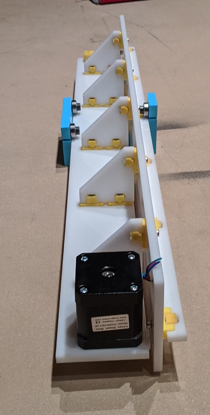
Assembling every piece together took some time, especially because we had some issues in the design of the structure. For example, the chassis didn’t have anything supporting it on one of its sides, so we had to laser cut two thin long rectangular pieces in order to create some kind of support. We also had to plan the assembly process carefully because we realized that there were some pieces that needed to be put together first and others that needed to be put right in the very end. I also need to mention the INCREDIBLE design of the connectors. The way Jake designed them was impressive. I spent some time analyzing the design in order to be able to implement them in future projects because the connectors were so effective, sturdy and also didn’t interfere with the general aesthetic since they are designed to fit in the small holes of the big pieces (see pictures below for reference). Thankfully, we had measured correctly the diameter of the pumps and so they fit exactly in the circular holes meant for them. Overall, the assembly process, though tedious, went pretty smoothly.


When we were almost done we also came up with a name for our product (“U Drink”) because we believe that the branding of a product is also important and we really wanted to make this week’s project as complete as possible. Then, I quickly drew something on my iPad, vinyl cut it and paste it on the front of the machine.

IFinally, I also tested the electronic connections using a multimeter (which indicated with a sound if to cables are connected) to avoid complications during the final stages of the project.
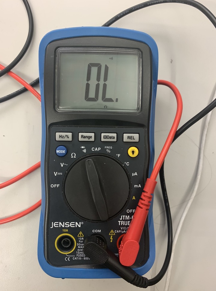
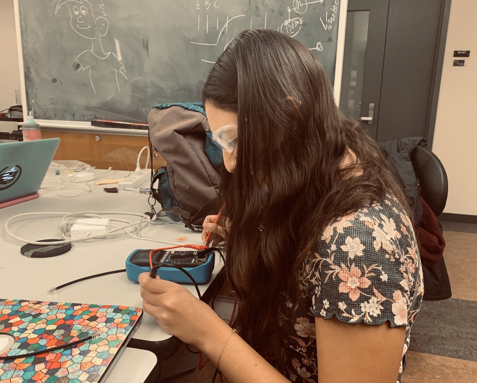
For this week’s assignment, we had to make a software interface using an input or output device we made. I decided to
I first downloaded Unity Hub following Diego’s instructions. I learned that one of the biggest perks of using Unity (a video game engine) to do projects is that it gives you the possibility of compiling for a really long set of options. He made some really good beginner-friendly videos (thank you so much Diego!) and I followed them step by step
Design and produce something with a digital fabrication process (incorporating computer-aided design and manufacturing) not covered in another assignment, documenting the requirements that your assignment meets, and including everything necessary to reproduce it. Possibilities include (but are not limited to) composites, textiles, biotechnology, robotics, folding, and cooking.
For this week’s assignment, I chose to focus on a folding and cutting technique that you can do with the Large Scale Cutting machine that is in the CBA shop: the Zund G-3 L-2500 which is a multifunctional digital cutting system.

On Friday 6th at 9:30 am I went to the CBA shop to get trained for the machine. It was very interesting and the machine was indeed impressive. I learned that it has three modules, each one with a tool and blade.
Steps to use the machine:
It took me a while to make the design. I wanted it to be something with an interesting geometry that would take advantage of the cardboard foldings that the Zuno machine lets us do. I started the design in Solidworks but after a while of sketching random lines without any actual progress, I realized that it was time to grab a paper and start brainstorming there. After a while, I decided to make the supports of my table for my final project, implementing the foldings and slots. I am aware that the material used is cardboard, which means, on the first glance, is not the best material for building a table, However, I wanted to face a challenge and I also think that it is important to explore more sustainable options when building new things.


While designing the supports for my table, I had to do more calculations than what I initially thought. I also realized that the stability of my structure is correlated with the size of the triangular part of the geometry. I had two types of foldings: one of the 45degrees and another one of 135 degrees. I also decided to make the 3D CAD in SolidWorks in order to make sure that the pieces would fit together in the best way possible and that there were no errors in the design. Thankfully, I did this because I realized that the space I had left for the slots was the width of the cardboard but it should be instead twice the width of the cardboard.

On Sunday 8th I went to the CBA shop to cut the cardboard. However, we run into some issues. I had made the part in SolidWorks, which from what I know, doesn’t have the option of layers. Because of this, I had to open the part saved as a dxf in Rhino. In there, I had to change the layers and save it as a dxf. This, although it sounds trivial, took me a while because neither Patricia nor I knew how to do it. After finally getting it done, I saved the new dxf file (with layers) in a USB flash drive and took it to the Zund. However, we ran into problems there too. The first problem was that when we opened the file in the monitor connected to the machine, the dxf had scaled down. After several minutes trying different thinks we realized that the Zund had recognized the design as if it was made using mm but I had used inches so we just scaled it up by multiplying everything by a scale factor of 25.4 to convert it into inches.


The second issue was that the machine only makes cuts on one side. However, my design would require a cut for an internal angle but also a cut for an external angle. There were two solutions:
For the first try, I tried the second option. However, something weird happened with the machine that, as you can see in the following pictures, didn’t make the proper cuts for the respective cut angles. S A D... but persistence makes perfection.


On Monday 9th I edited again my SolidWorks part in order to enlarge the triangle portion a little bit to make the structure more stable. I also decreased the length of the slot in order to make it fit exactly.
I then went to the CBA shop again at 2pm, opened Rhino and imported my dxf files. I set the layers to their corresponding lines, save this new dxf in a usb flash drive and took it to the Zund. There, Patricia helped me to put a new cardboard on the bed of the Zund and to operate the machine. She first had to change one tool but after making sure that they were tightly held, to avoid any damages, we were set to go.
First, we opened the CutManager and made sure that the correct materials, thickness and tools were selected.

Then we plugged in the flash drive and opened the DXF in the CutEditor. There we scale it with the correct factors and then set the layers to the corresponding tools:


We then saved it and sent it to the Cute Cube. There we matched the layers with the respective tools.


We then aligned the cardboard with the machine by running the laser dot along the edge of the material. Finally, we set the reference point and started cutting... We waited and then took the cut part out, bent the parts and TA DAAAAAA IT WORKED!!!!!!!! 3 more to go!

In order to accelerate things, we decided that it would be a good idea to run the commands without taking out the cardboard and putting it again and loosing all of the assignments of layers to tools. By doing so and just changing the reference point (so that we were not cutting in the same position) we managed to finish cutting everything in less than 30 minutes! Finally, it was assembly time.

It was now time to make the two parts fit together. It was a little snug and after a little bit of fighting with the cardboard and Patricia’s help (THANK YOU SO MUCH!), I finally made them fit!!!!!!!!

