Final Project: Automated Shrine
At long last, the final project! Throughout the duration of How to Make Almost Anything, we were tasked with creating a final project that used all the skills we've been learning in a big culimation. We were given the freedom to choose basically anything we wanted to build, as long as it incorporated the techniques we covered each week.

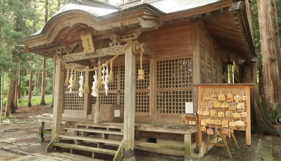
If it is not already clear from the other weeks, I am a big fan of Japanese shrine architecture. It's a really unique style, and for this final project, I wanted to take inspiration from this style, but build something with a modern twist.
In common tradition, when praying at a Shinto shrine, there is often a donation box in the front of the shrine. To use the shrine, you throw a coin in the box, then ring a bell, clap your hands, and bow. The god of the shrine will then hear your wish and (hopefully) grant it!
For this project, I wanted to put a modern spin on this tradition. My goal was to build a wooden shrine, but automate the praying process! Basically, every time a coin was put in the donation box, an electronic sensor would detect it, and then the doors would swing open like almost magic.
The Shrine Base
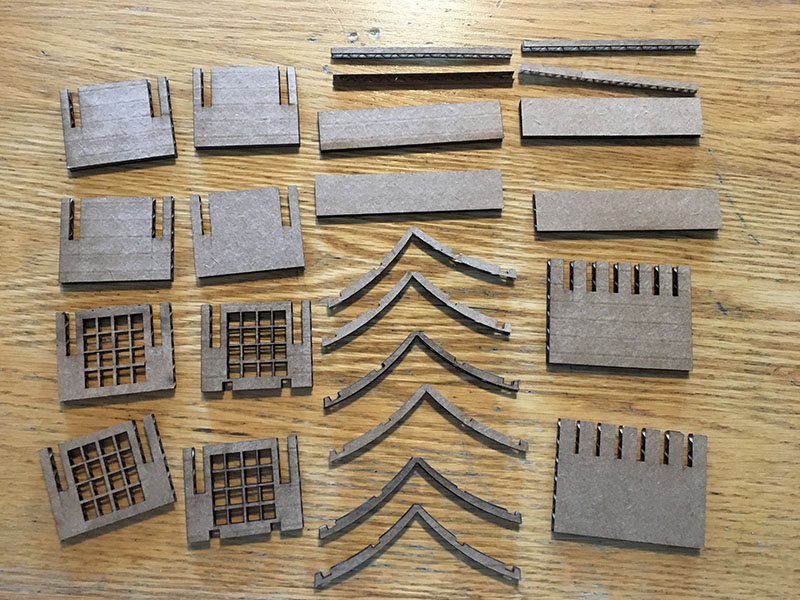
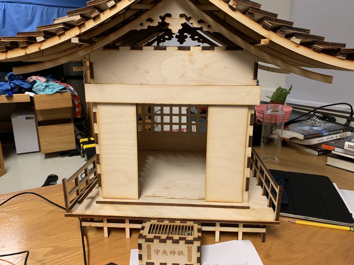
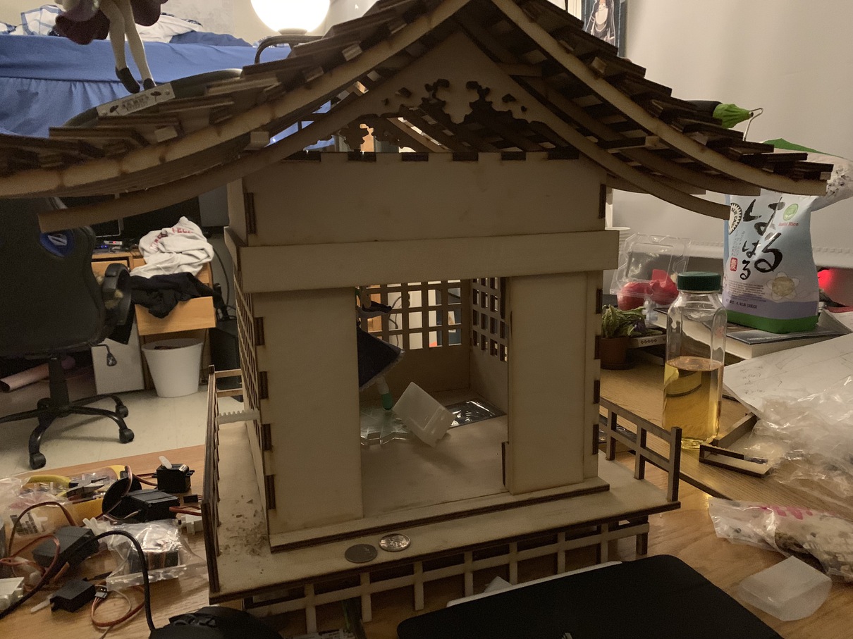
Earlier in the class, I built a press-fit mini shrine out of cardboard. The wooden frame for my final project shrine follows a similar philosophy, except with laser-cut plywood and some wood glue to hold everything together. I had actually designed this shrine last year before the class started, but I had not thought about automating it, so the design needed some live fixing to be of use.
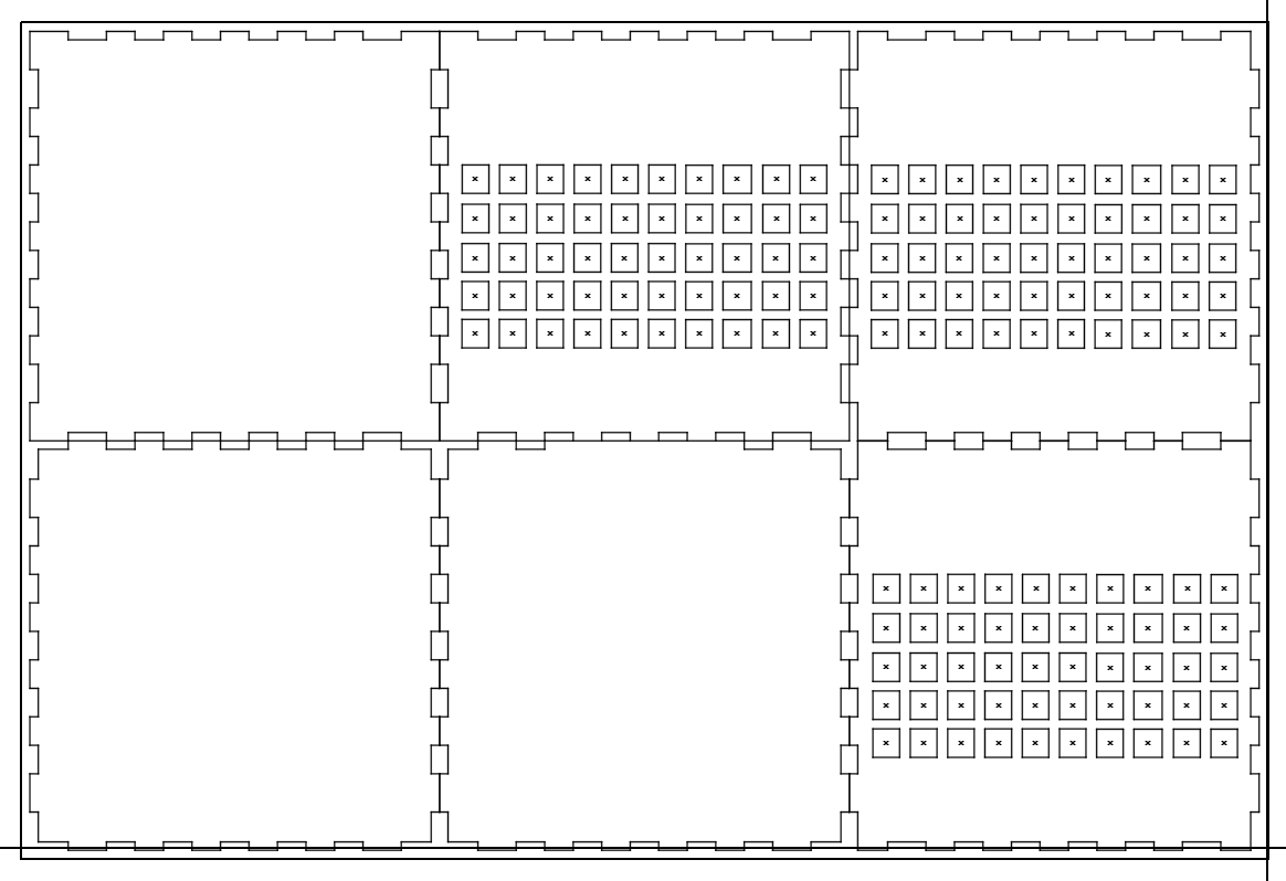
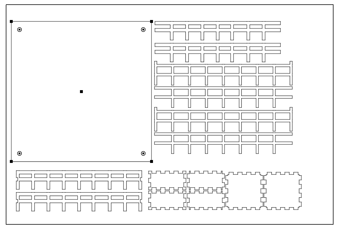
I started out the CAD for the shrine base in Illustrator. I used MakerCase as a starting point, which let me create a bunch of square grids with fingers on the end to join together. Starting from there, I basically just decorated the shrine with a bunch of square holes to act as windows, and cut a big square out of the front as an entrance.
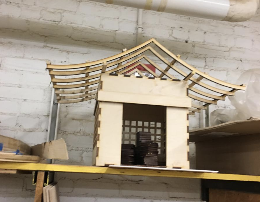
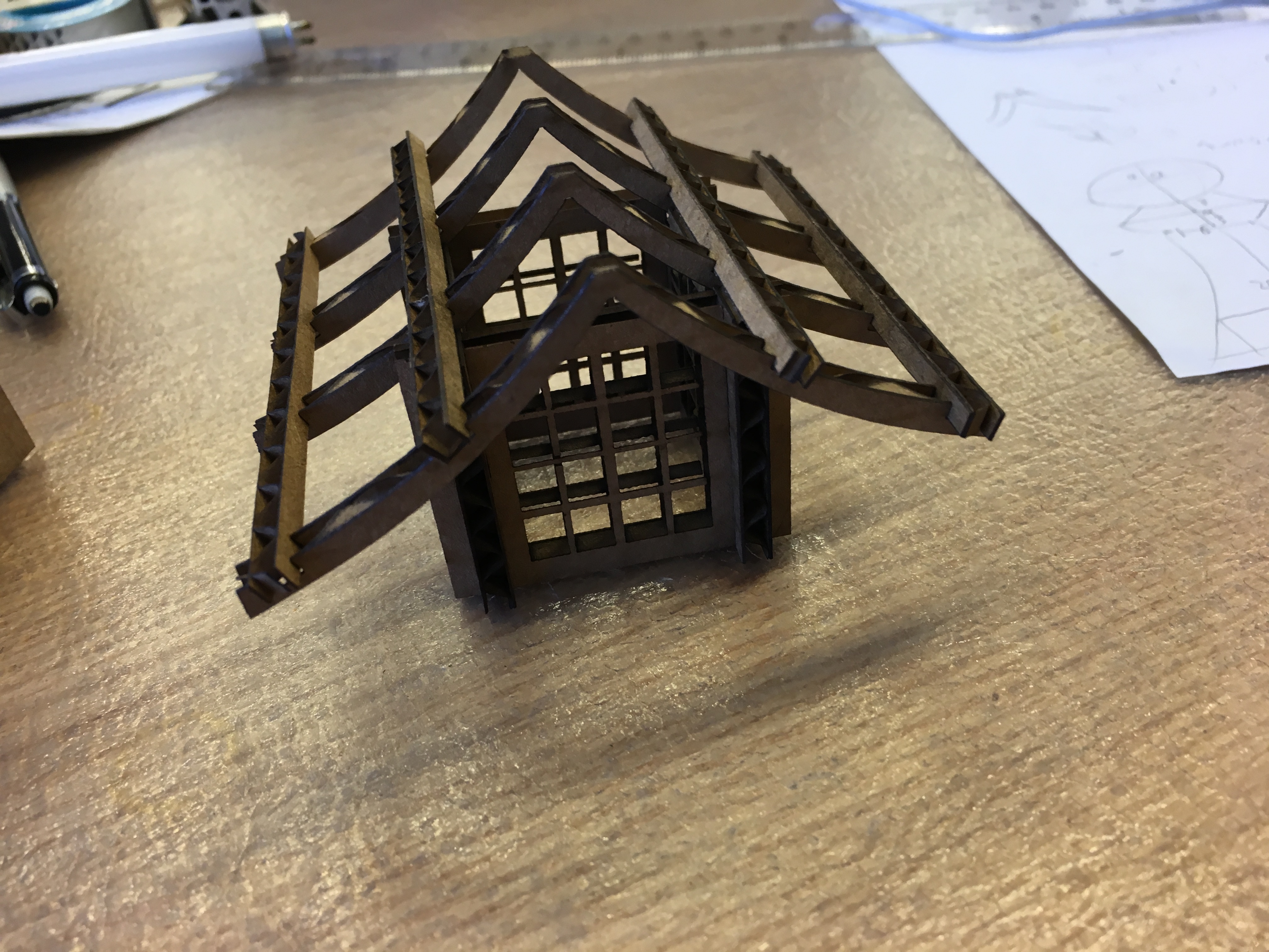
After the base square-ish box was done, it was time to work on the roof. Similar to the cardboard shrine, I achieved the curve by laser cutting, although for real shrines they actually bend the wood to get the curve effect. I also added a bunch of perpindicular supports to hold up the eventual roof that would go over the whole project.
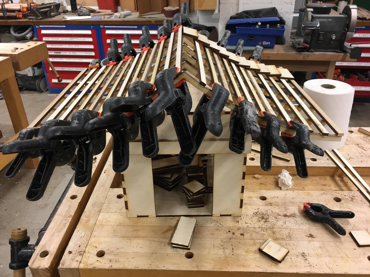
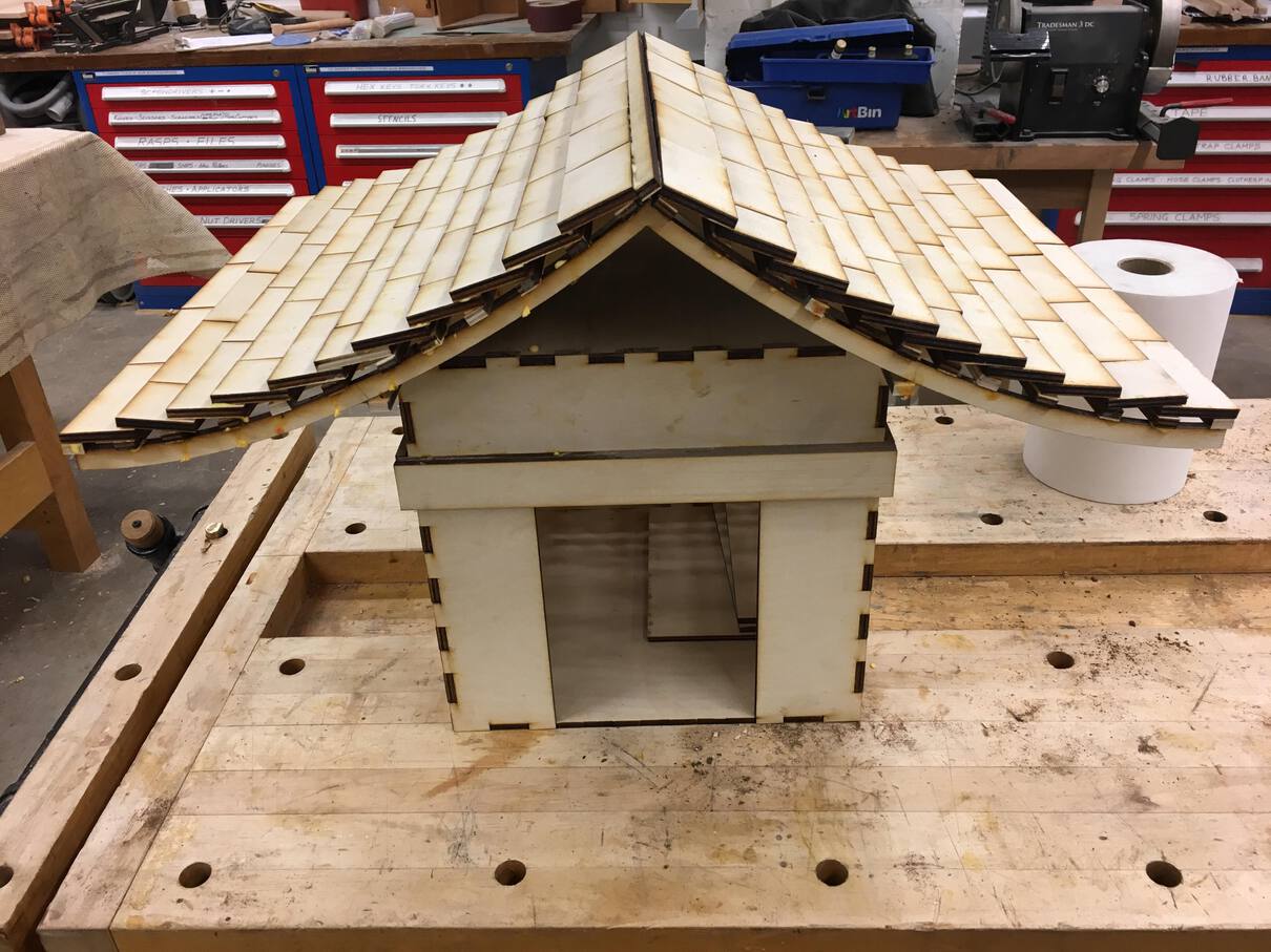
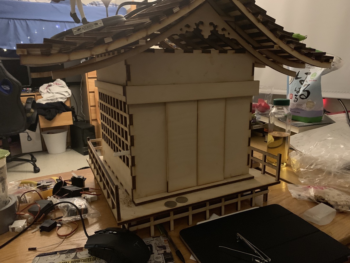
To finish the roof, I cut out a ton of small rectangle tiles, and layered them on top of each other so each tile was always ontop of the one below it. This creates a nice roof-tile effect and is also great for keeping out water!
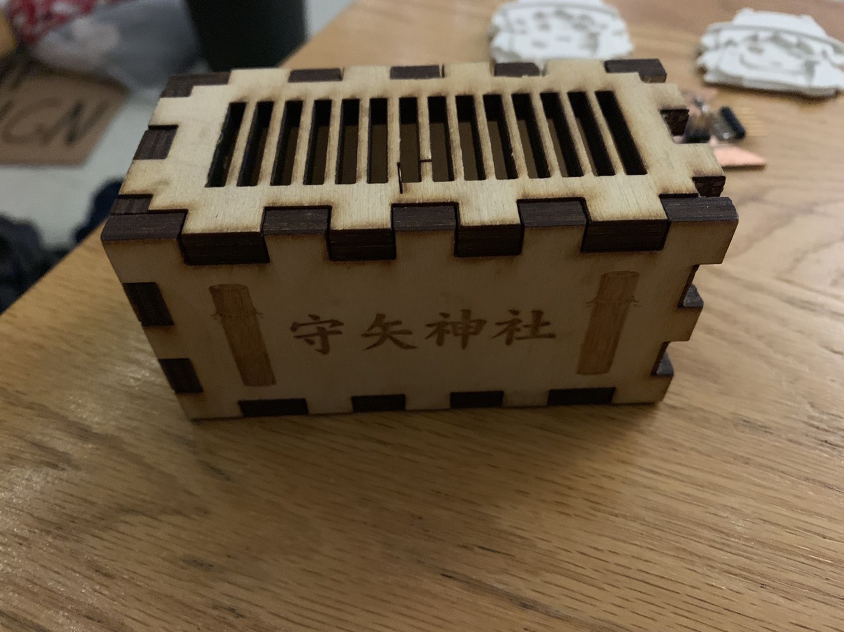
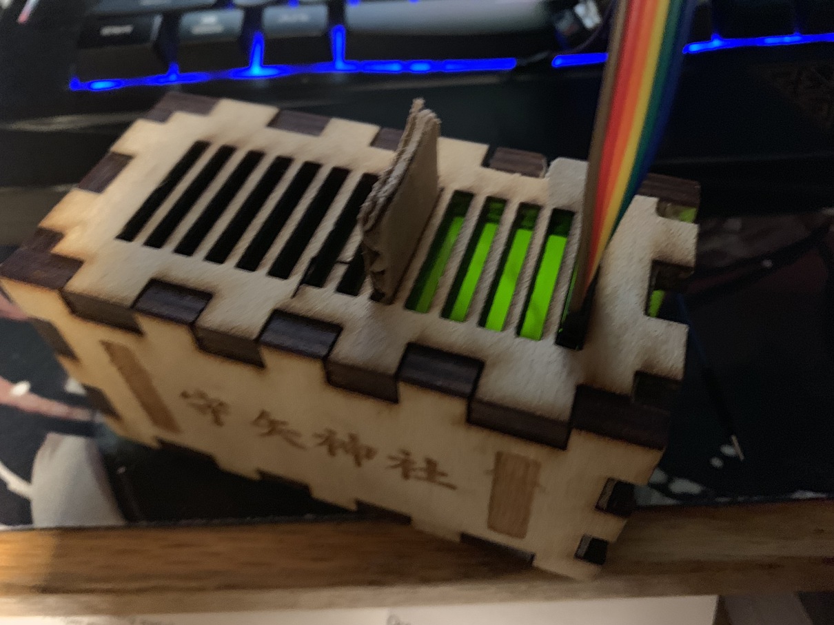
The donation box is another simple design. It's just a six-sided box, again held together by press-fit edges along with some wood glue. I cut a bunch of slits out of the top to allow coins to fall in, and I also pried open the side to stuff in some electronics. The front is a laser engraving of "Moriya Shrine", the real-life shrine that my design is based off.
With that, the wooden shrine base was finished! This was basically the starting point for my final project -- I have a wooden shrine, and now I want to automate it. But since I had designed the shrine without thoughts of automation in mind, I would have to be a bit tricky to pull this off.
The Donation Box
First up on the list was to put a sensor in the donation box to detect if a coin had been placed inside! For more in-depth details here, see the weeks on Input Devices for how I designed the board, and Networking for how I connected the board to a Raspberry Pi over serial.
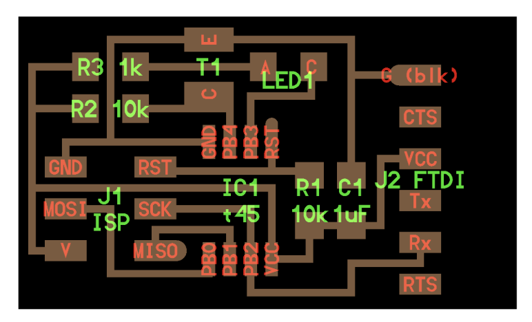
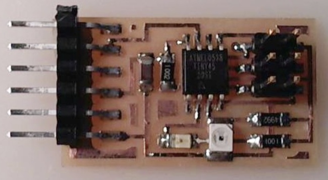
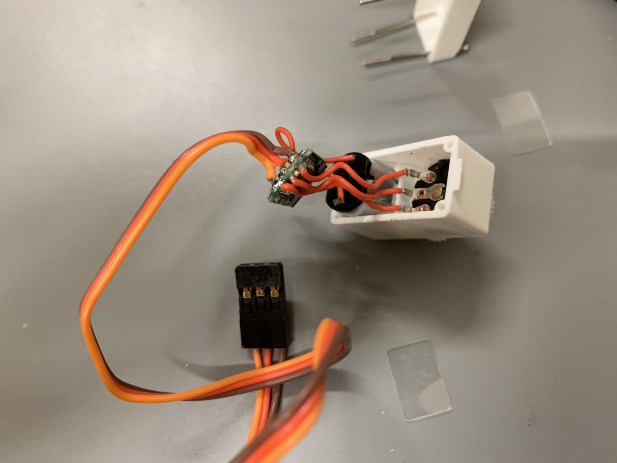
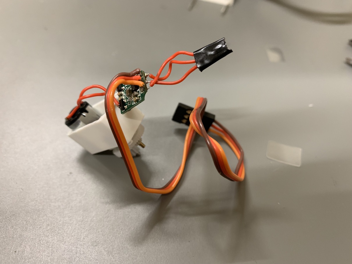
The plan here was to use an infrared LED along with a photoresistor to detect a coin. The LED would go on one side of the donation box, and the detector would go on the other. If a coin is placed in, it would block the infrared, and the board could then detect it and send a signal back to the central Raspberry Pi controller.
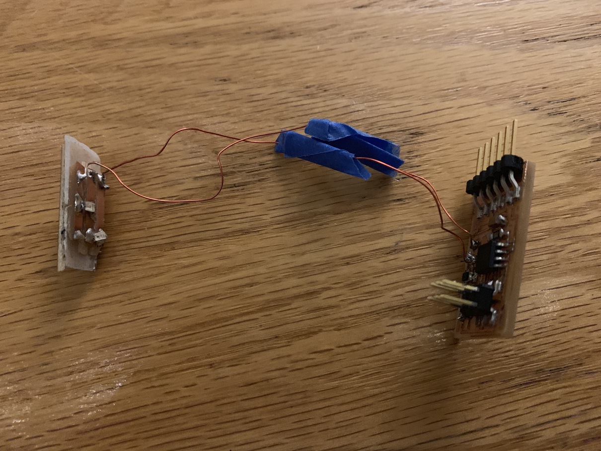
However, I didn't plan the design too well, and ended up having to solder on some jumper wires, as Neil's design I was basing the board off of had the LED and photoresistor in the same physical location, which obviously won't work to detect the coin. I also attached a green LED along with the infrared one, just to make it easier to debug my circuit which I didn't exactly trust to behave without flaws.
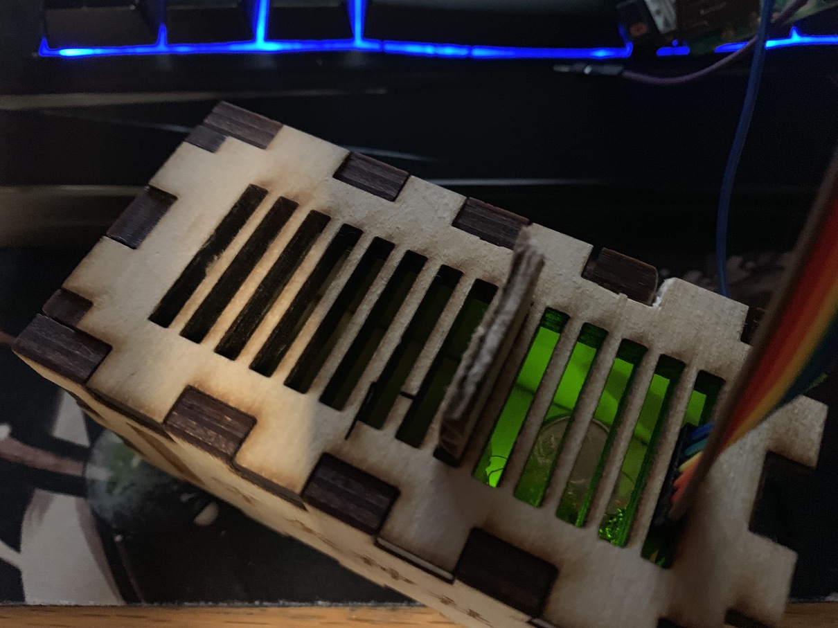
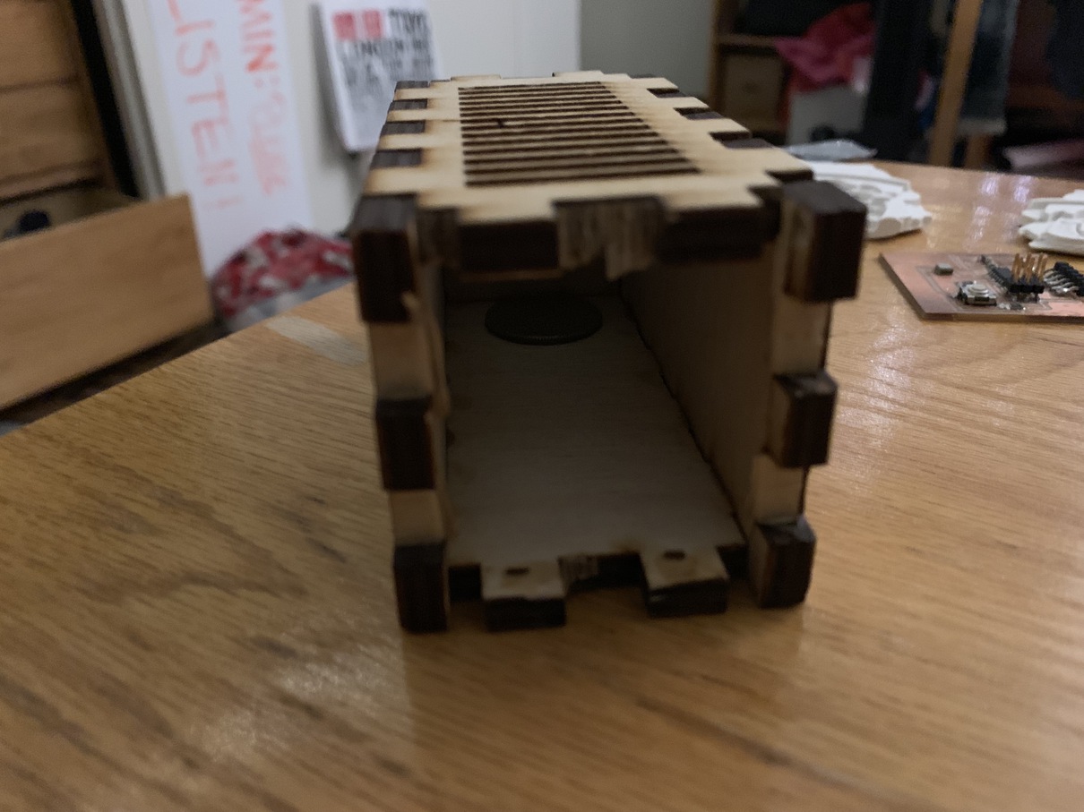
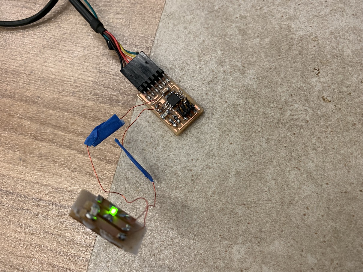
In the end, even after using a bunch of tricks like lowering the resistors on the LED and photo-detector, I still could not get the board to operate well more than a few inches apart. So I had to use a piece of cardboard to divide the donation box in two, wiith only the part with the LED working as a detector. I used a bit of hot glue to stick everything together, along with some geometry tricks to get the wires to come out of the slot.
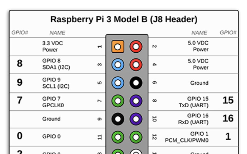

With that, the donation box sensor was working! I hooked up the board to the central Raspberry Pi controller usinig the GPIO pins, which communicated the readings through serial. For more on that, check out the Networking week.
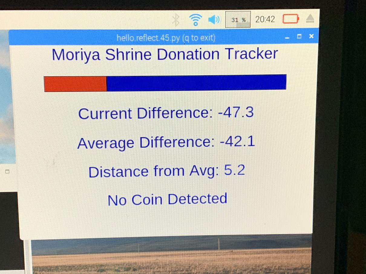
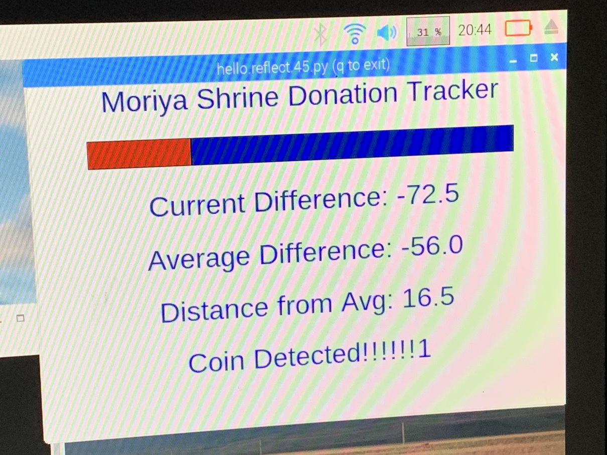
Next, I needed to actually figure out when a coin was in the box! I decided to do all the computation on the Raspberry Pi rather than on the embedded board, since the feedback loop was a lot smoother when I could test in python rather than havinig to constantly re-flash the board. So, my setup would be the board sending raw sensor values directly to the Raspberry Pi, and then a python program would be constantly reading the signal for signs of a coin.
    //filter is the sensor reading
    avg.append(filter)
    if len(avg) > 1000:
       avg.pop()
    currav = sum(avg)/len(avg)
    dist = abs(currav - filter)
    if dist > 30:
        coin_detected = True
The Sliding Doors
The next step, and the hardest for sure, was to get the doors to open! For more details on this part, check out the week on Output Devices, where I talk about setting up a rack and pinion and programming it.
The basic idea here is to convert the rotational motion of a servo into a linear movement by using a gear and a slider with teeth on it. When the gear spins, it pushes the slider, which then can be attached to the doors to open and close them.
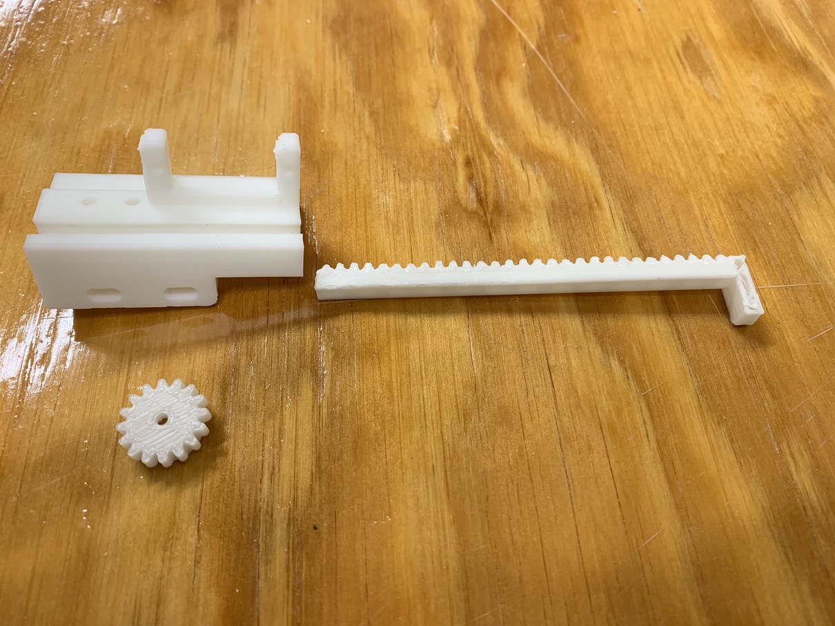
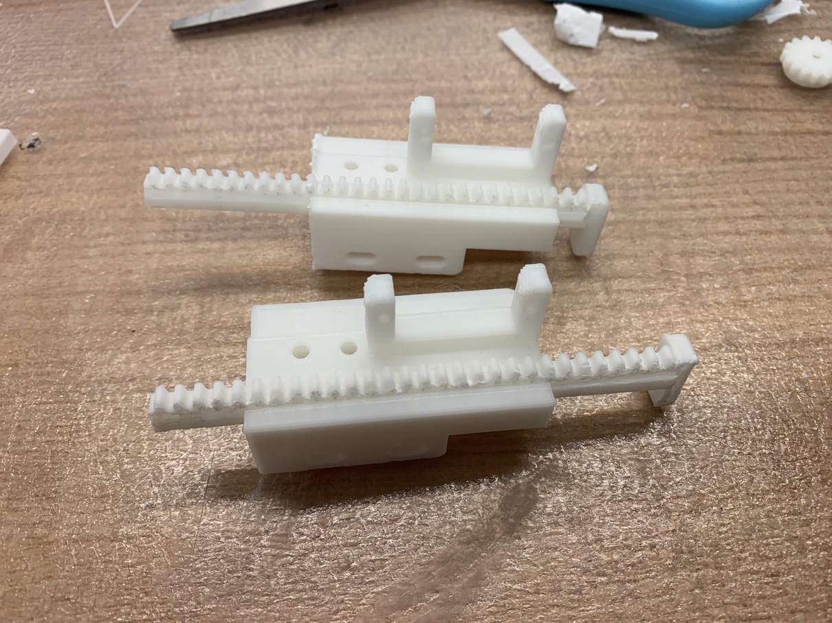
The hardest part here was actually dealing the artifacts of the 3D printer I used. I had to enable supports, or the part would not print correctly, but the supports often came out super hard and were very tough to remove. I eventually had to use a pair of pliers and an iron sanding rod, but the slider could now smoothly move inside its rack.
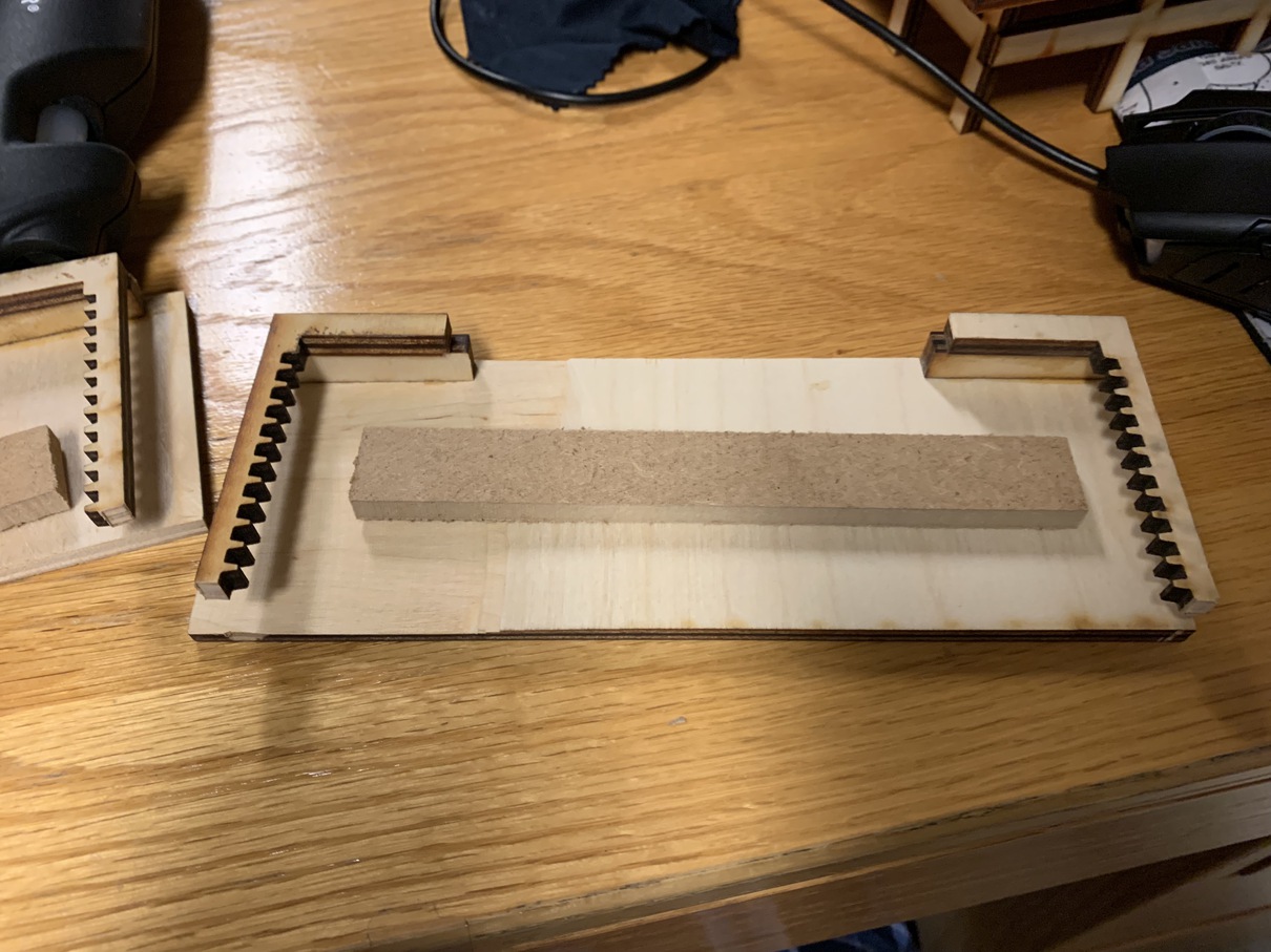
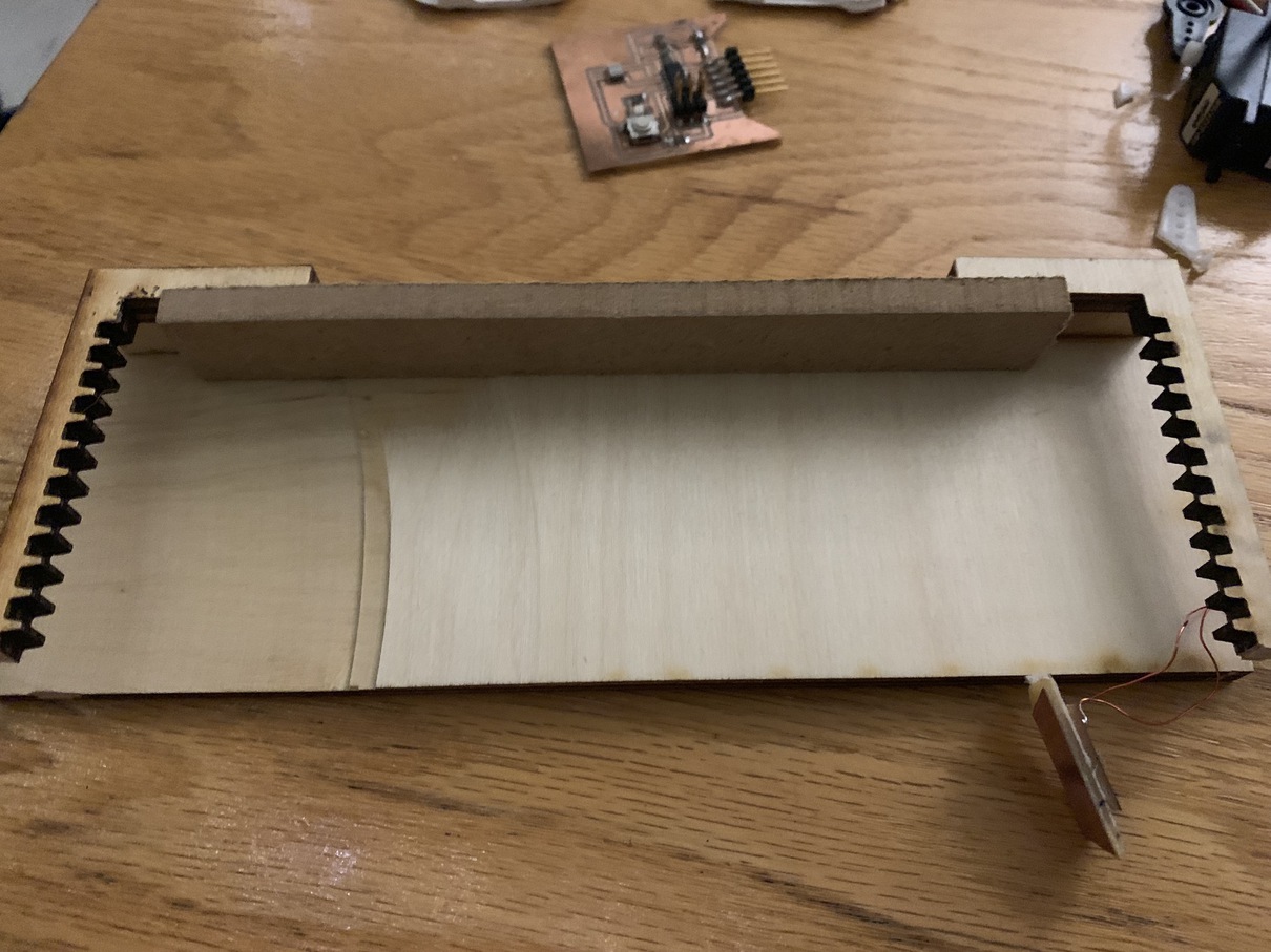
To connect the rack and pinion to the shrine base, I hot-glued a few pieces of wood to the back of the sliding door to create a surface for the printed slider. I then glued the slider to the door, so that it could push and pull along the same axis.
With that, the door could now move! There was one big problem, though. Since the servos can only turn 180 degrees, the horizontal movement of the doors was limited by essentially half the circumference of the gear, which is not very much. To get the doors to open fully, I would have to be a bit more creative.
There were really two possible solutions here. One was to make the gear bigger, so that the half circumference could cover more linear distance. I actually did attempt this a little bit, but it became hard to rescale the gear while maintaining the correct tooth size, and I realized I would need a pretty big gear in order to do the distance I was thinking of.
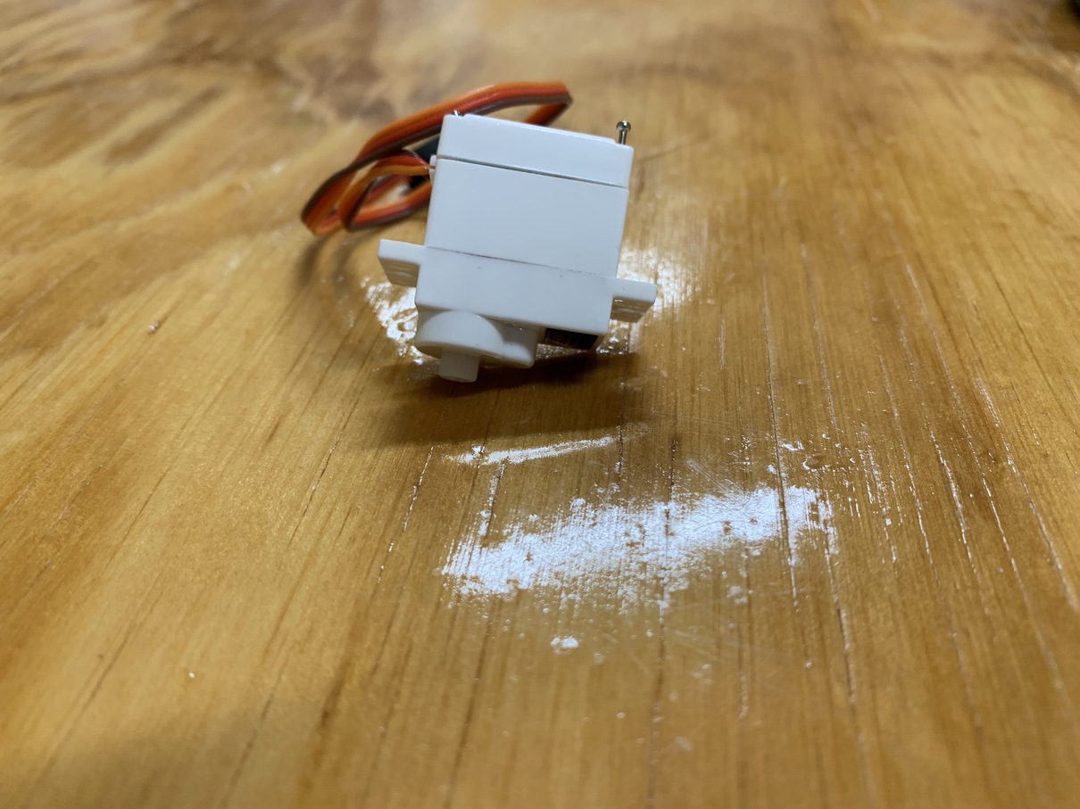
Instead, I tried a different approach -- using continuous motion servos, which can rotate freely in any direction. It turns there is a pretty straightforward way to convert regular servos into continous motion servos, as the servos are powered by motors which essentially do this behavior anyways.
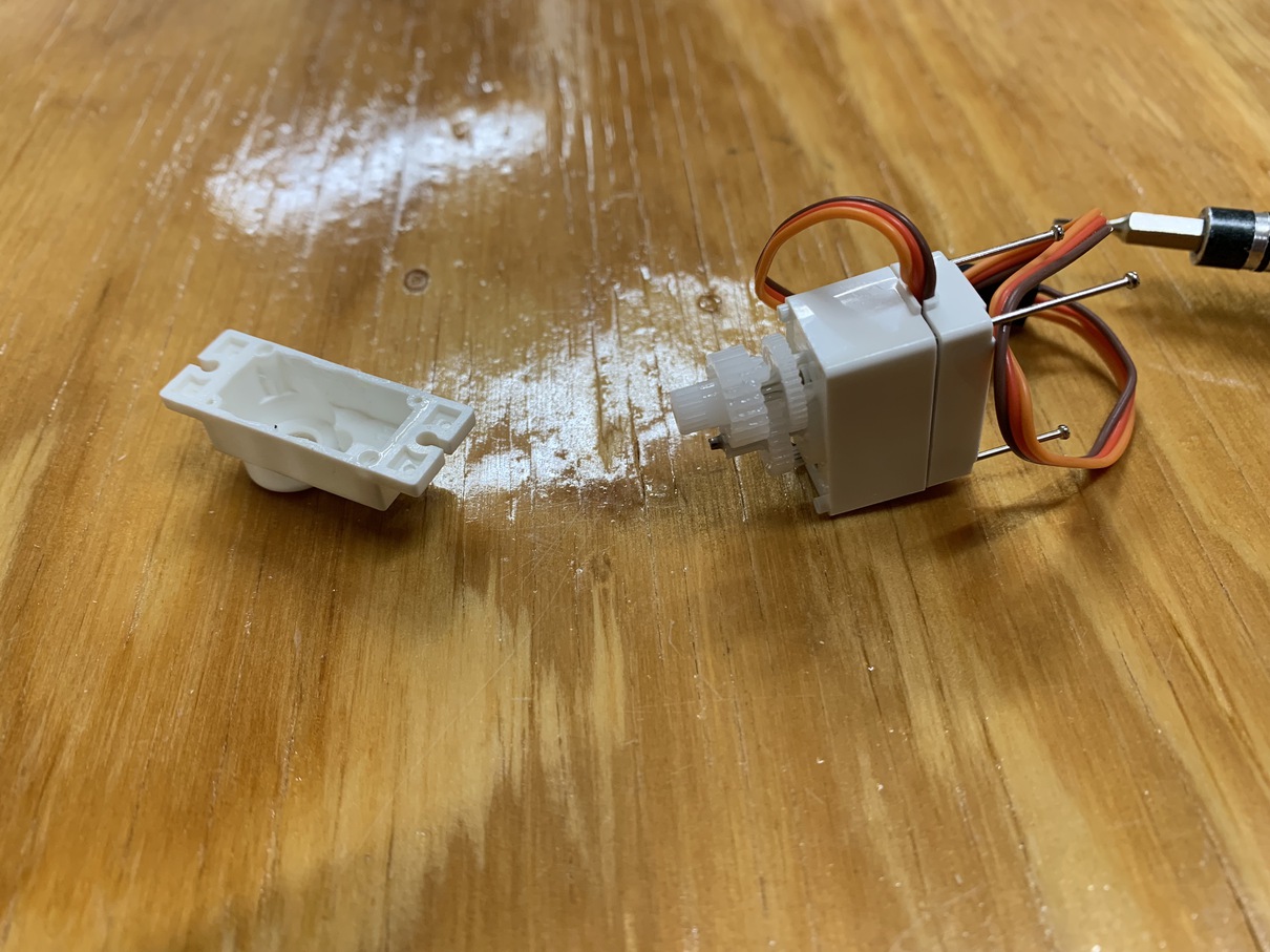
After opening up the inside of the servo with a little screw, I ripped out the three wires that connnect the servo controller to the potentiometer. The potentiometer is a device used for measuring the angle at which the servo is currently rotated to. By removing it, we can trick the microcontroller into thinking that the servo is never at the position it wants to be, so it will keep spinning.
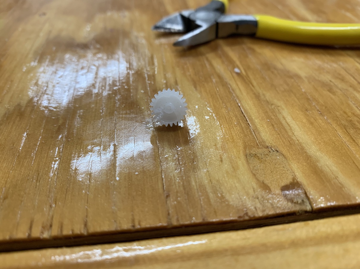
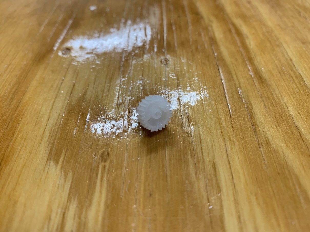
The next step is to modify the gears themselves. Most 180 degree servos have top gear with a little notch in the bottom to stop it from overspinning. Since we do want it to overspin, I cut the notch of plastic off with a pair of sharp pliers. I also re-drilled the inner hole to be a perfect circle rather than the half-circle it was before.
And with that, the servos can now move freely, as many degrees as we want! Well, in theory. There was actually a lot of trial and error here in getting the continuous rotation servos to work. I ended up going through a bunch of servo types, from big to small, testing which combinations of gears and motors could work without falling apart. In the end, I ended up using a real continuous rotation servo, but I subtituted the head gear (the one that exits the servo body) for the modified head gear I had made in the pictures above.
To actually control these servos, we "pretend" to send a PWM matching a specific angle, but we actually are only specifying the direction we want the servo to spin. Basically, the hacked potentiometer always thinks the servo is at 90 degrees, so if we send a signal to spin to 80 degrees, the servo will spin counterclockwise forever, and vice versa for 100 degrees. So to specify how much we want the servos to spin, we have to use our own timing -- such as sending a signal for 80 degrees (spin counterclockwise) for half a second, then sending a signal for 90 (stay still).
Putting it All Together
With the shrine base, the donation box, and the sliding doors all complete, it was finally time to piece the project together! Since we had the Raspberry Pi as a centrallized controller, this process was pretty smooth. The phiilosophy I used was as such -- we trust the embedded boards and servos to do as little work as possible, basically just to take in raw input and recieve low-level commands. All the processing is instead done on the Pi itself, which determines when each of the smaller units should activate.
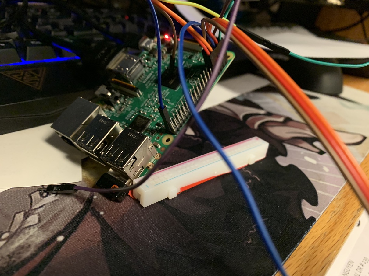
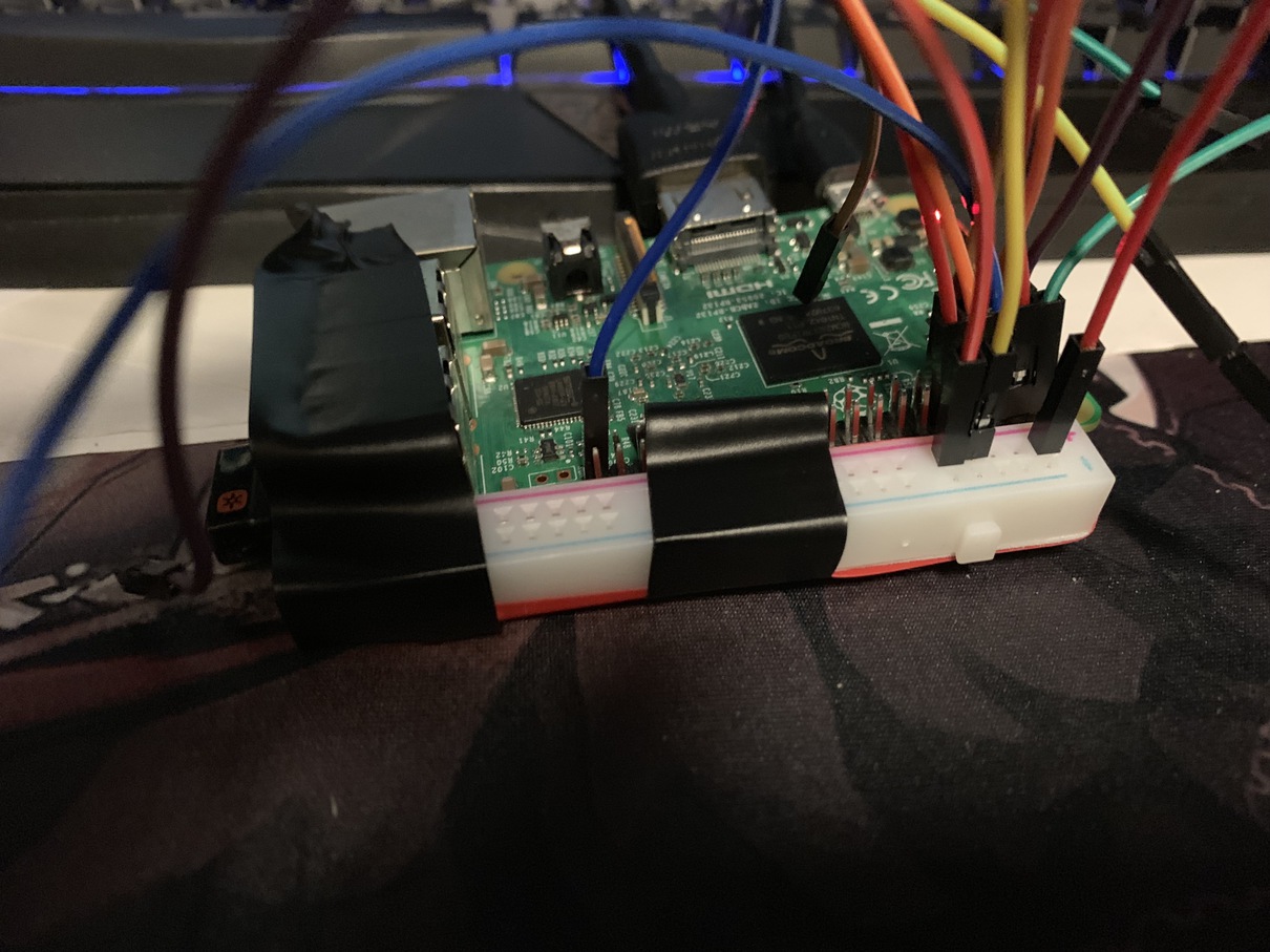
Wiring-wise, the Raspberry Pi only has a limited set of GPIO pins, so I had to be a little hacky here. Namely, there were three devices that needed 5v current, but the Pi only has two 5v output pins. I ended up cutting out a part of a breadboard to use as a current splitter, and let the two servos share the same power source. The other pins all simply head to Ground, the Rx/Tx pins for the photoresistor board, and the GPIO 2/3 pins for controlling the two servos.
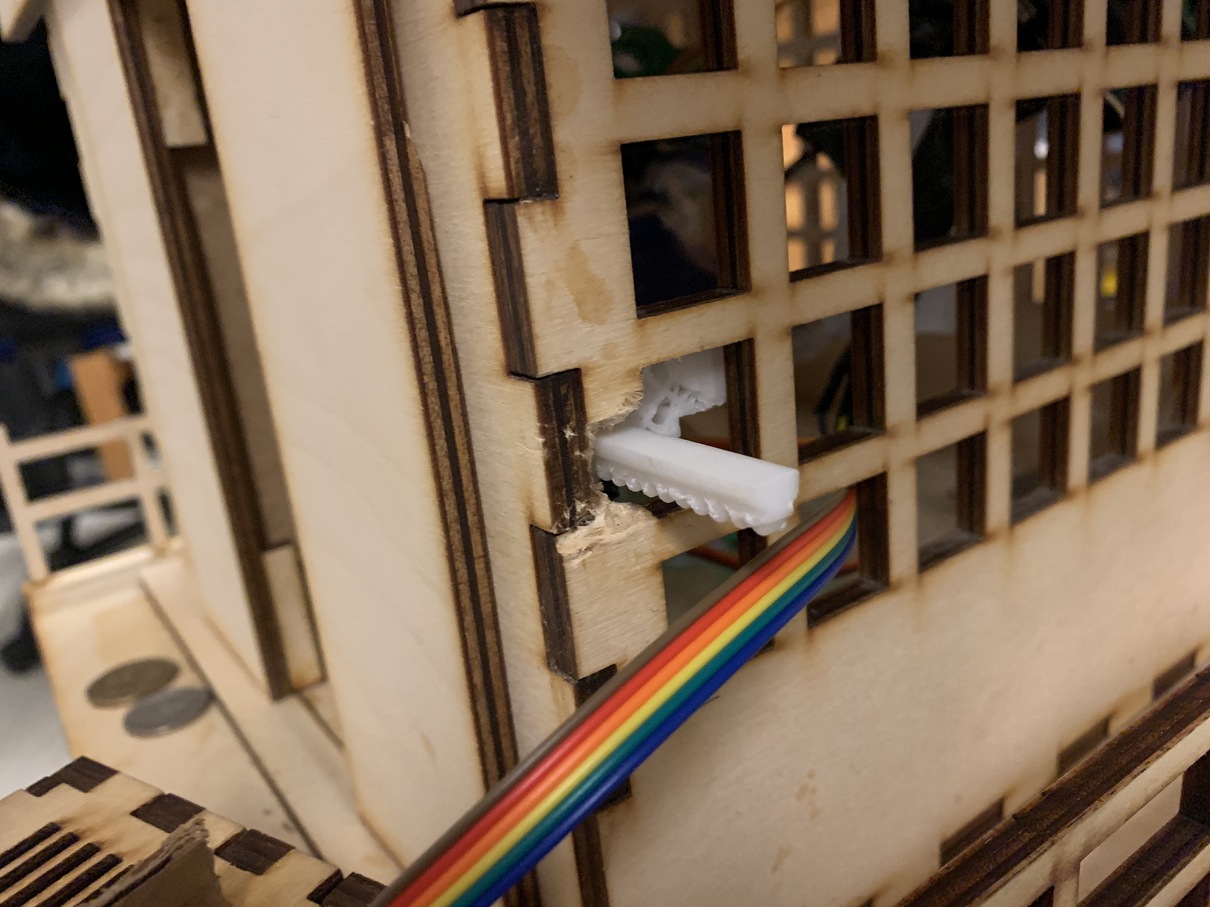
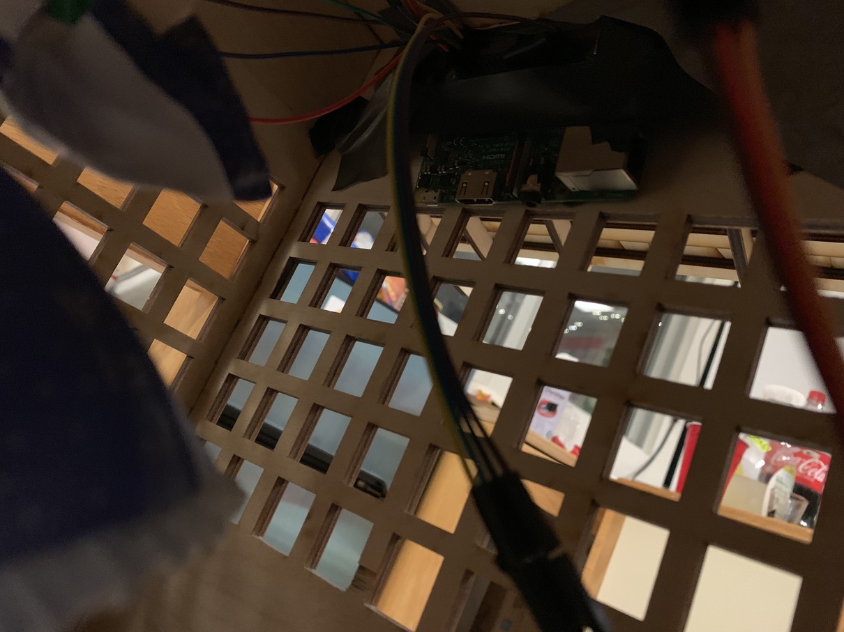
At this point, all that is left to do on the hardware end is attach the sliding doors to the shrine base in a concealed fashion. I ended up hot-gluing the 3D printed material to the side of the shrine. I had to carve out a little bit of the wood on each side for the slider to slightly leave the shrine interior, to give it room to slide the doors completely open. I also re-did all the wiring so the Raspberry Pi could be mounted inside the shrine itself, hiding it from the outside.
And that's it! It took a loooot of trial-and-error and experimentation, but the automated shrine of my dreams has come to life!
Materials used:
- Plywood (~$100)
- 2 Servos (~$10)
- Raspberry Pi (~$30)
- Wires (~$2)
- 3D Printer Resin (~$5)