Background
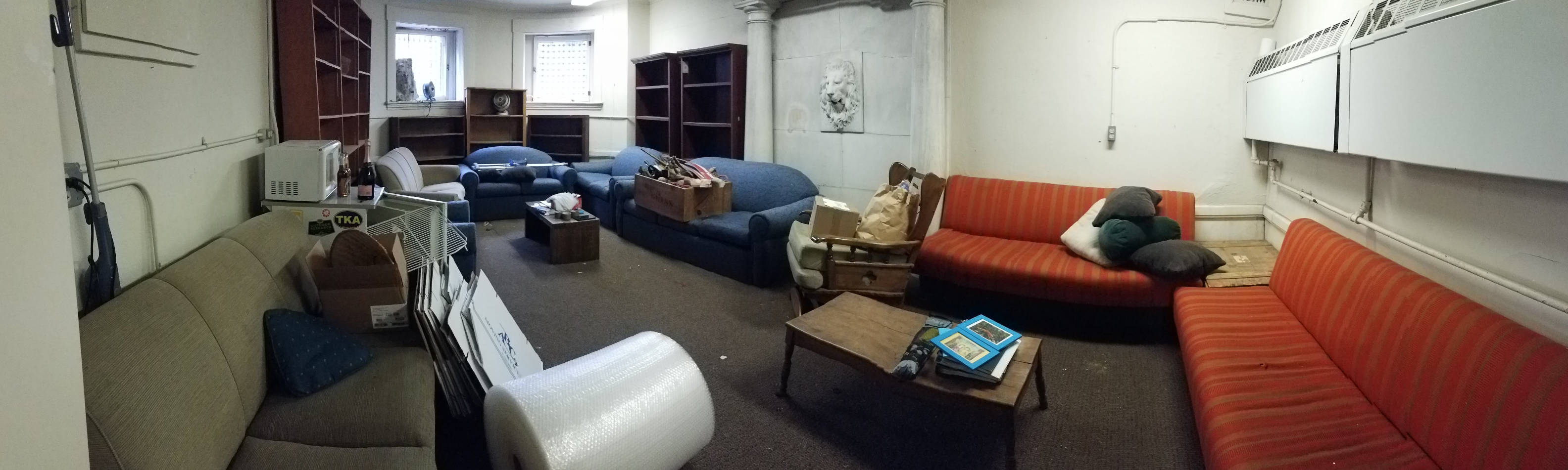
I'm the Gear Tsar for the Harvard Mountaineering Club. The HMC is a phenomenal group, full of history, and it means a lot to me and many others. We just left our old space, and we're missing an old marble lion head that used to be set into the wall (the University wouldn't let us bring it, the jerks). I want to work on making a replica with some added functionality (probably seeeeecret).
Initial modeling
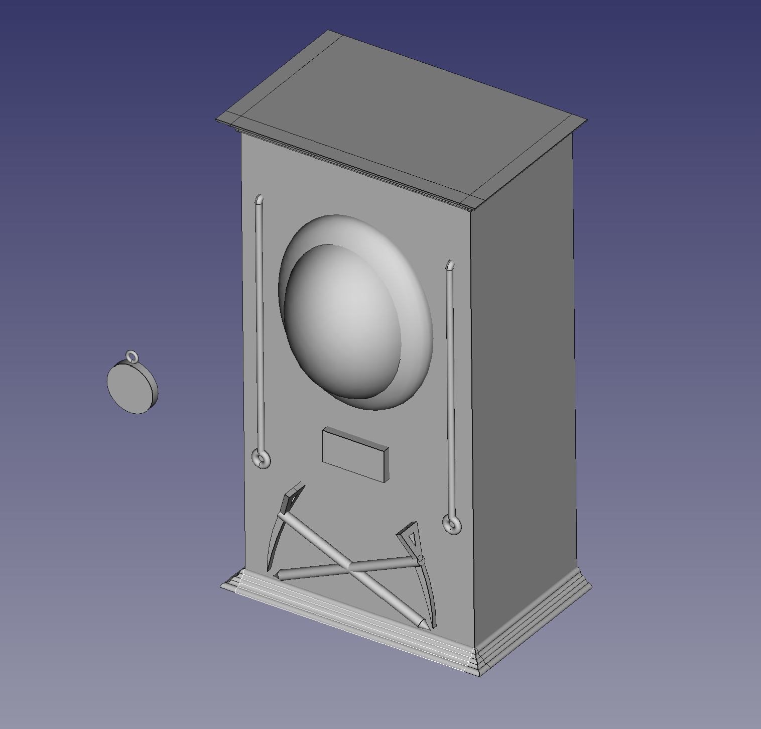
For week 0, I tossed together a quick model of the final design I wanted. This is very bare bones, but gave me something to start with.
Building the programmer
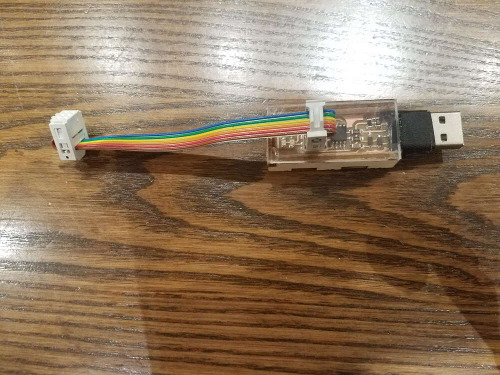
For week 2, I made the FabTinyISP that Brian documents in the course page. This was used EXTENSIVELY. It programmed all the microcontrollers for the circuitboards I designed to add the puzzle functionality of the box.
Practice scan of the low-quality model
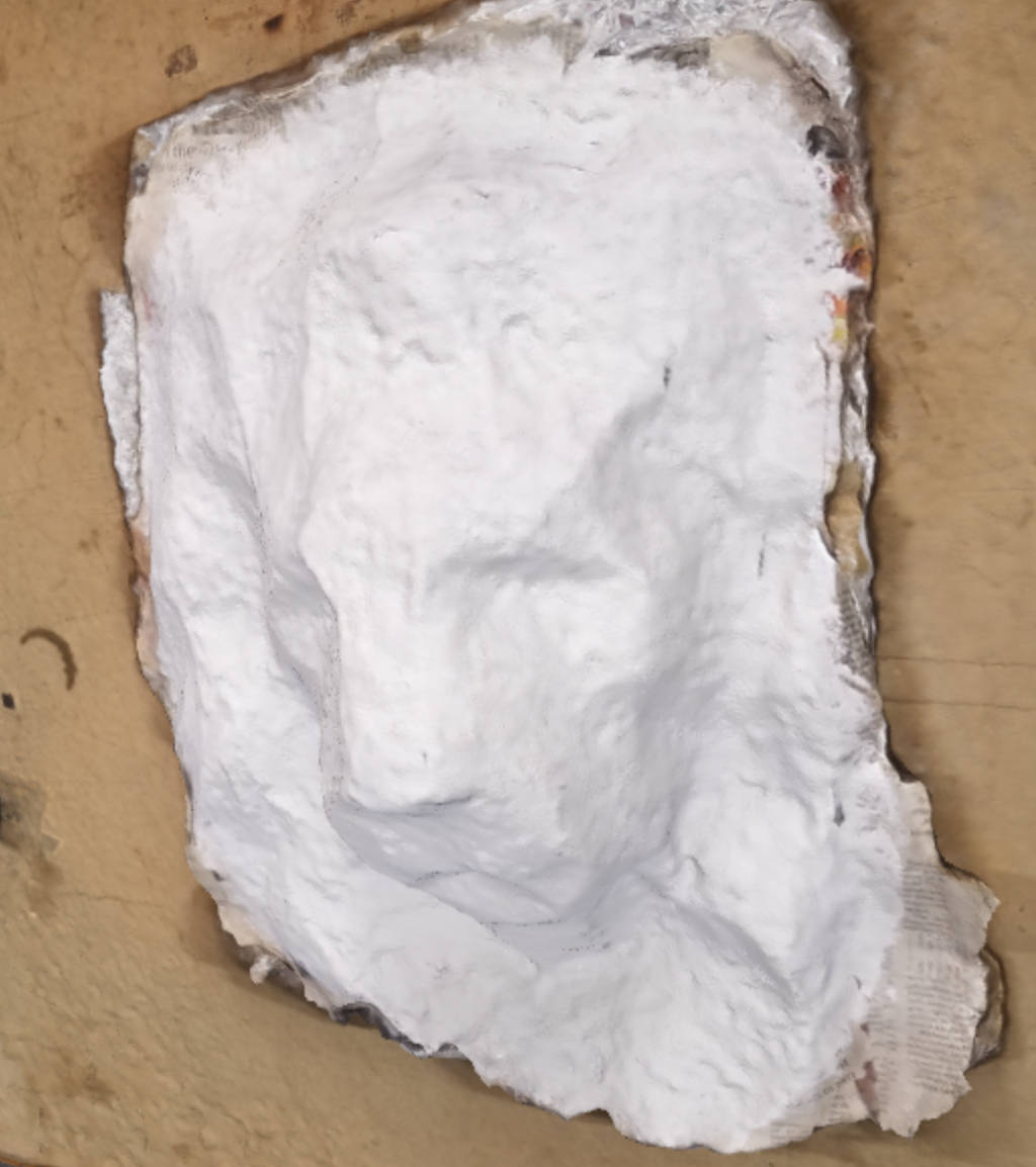
I didn't have access to the original lion head, as the building was in construction. However, we did make a low quality "mold" of it with some tin foil, newspaper, and glue before the construction started. If I didn't get access to the original, this was going to be the base for a model I would have made by hand. As it turned out, it was only needed for photogrammetry practice. Check out my week 3 documentation on how that went.
Modeling the lion head
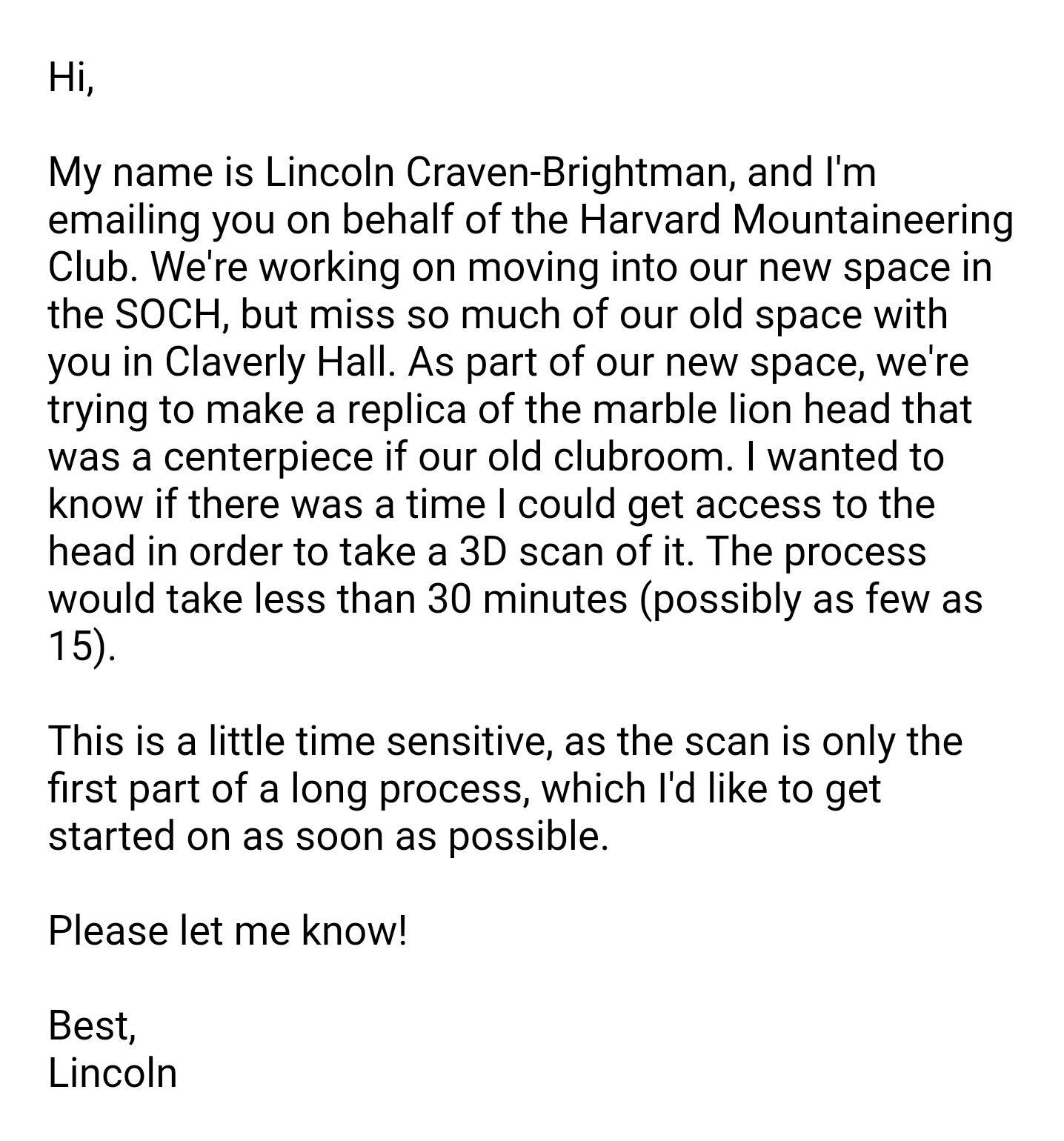
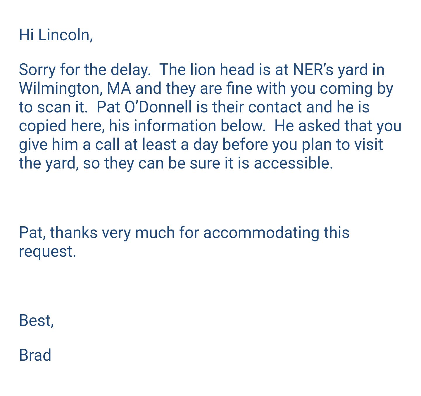
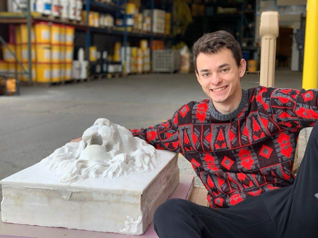
The original lion head was difficult to track down. I sent out a long chain of emails, and finally got in touch with the construction company that was storing it (four weeks later!). I headed out to Wilmington, MA, and took about 150 photos of the block that the workers had kindly pulled out of storage for me.
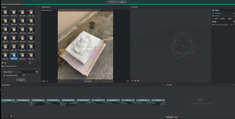
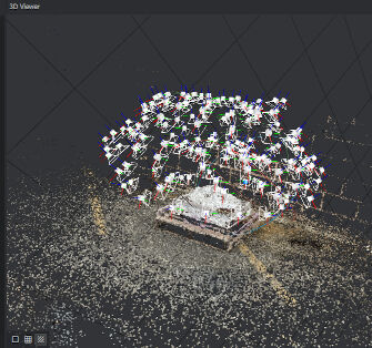
I brought all the photos in to the lab at Harvard, and ran them through Meshroom. The process was remarkably easy -- load all the photos in and press start. The model generation took 3 hours, but it was really cool to see some of the intermediate steps -- the structure of the image and the location of the cameras were identified by the software, which made a neat point cloud to look at.
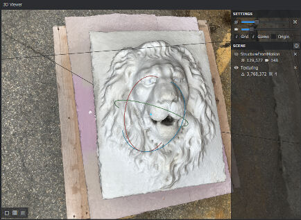
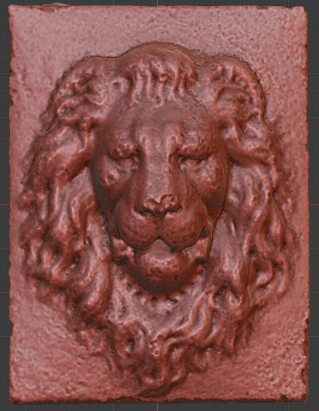
Finally, I got the model. It had a large view of the entire scene, with decreasing quality as it got away from the target. The model in frame, however, looked gorgeous. Some of the surfaces ended up bumpy, particularly the nose, but a lot of the original details were present. I loaded the mesh into Meshlab and cut it down to just the head, and used that in my week 7 molding and casting assignment. That, however, is a long shot from casting the entire head. I may end up only casting a part of it for the final presentation, as a sort of proof of concept.
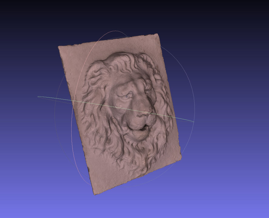
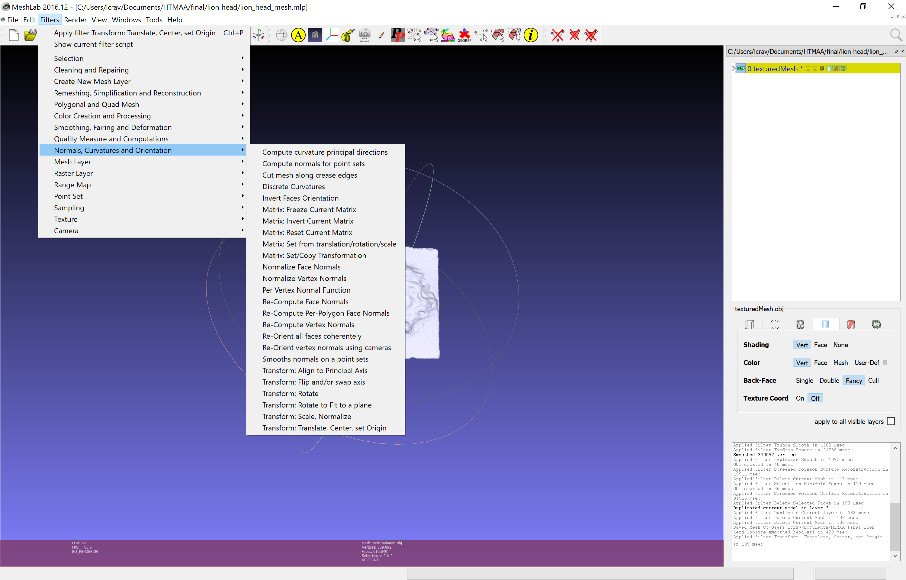
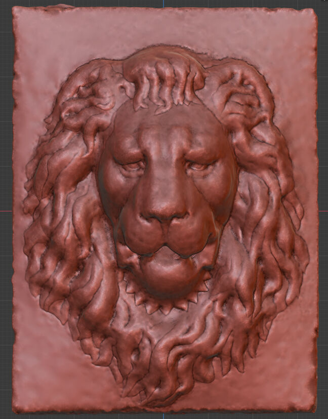
With that model, I ran a couple of smoothing operations. First, I spacially aligned the mesh and ran it through a Laplace smoothing filter in MeshLab (don't worry, I'm confused by the mesh-software names too). All of that was in the filters tab, which seems to be where the power of MeshLab is. I imported the smoothed mesh into Blender, which was honestly a polished joy to work in. After about four hours of sculpting "by hand" over a couple sessions, I got a really nice looking model. Some of the hairs aren't as detailed as they could be, but this got me pretty much to cast ready.
Puzzle Modules
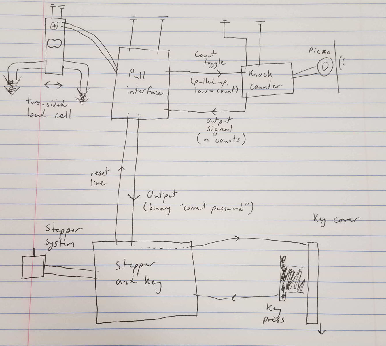
For the functionality of the puzzle box, I wanted to hook up modular boards. I struggled a bit with how to present this final project to the class while also keeping it a unique secret for the club. I settled on a password system, with a couple fun input devices as the ways to enter that. The system works as follows: The password control is located in a board. Attached are a load cell board that sends a digit selection signal to the password board, as well as a "go" signal to the other input device -- a piezo transducer knock counter. I developed this in week 8, and it counts up to 9 knocks while the go signal is held. When the go signal stops, the count is sent to the password board, which puts that number in the digit that was selected. If that matches, I might open up another button, which will operate the final motor that puts out the ~secret surprise~. I practiced with some stepper motors for week 9 with this in mind.
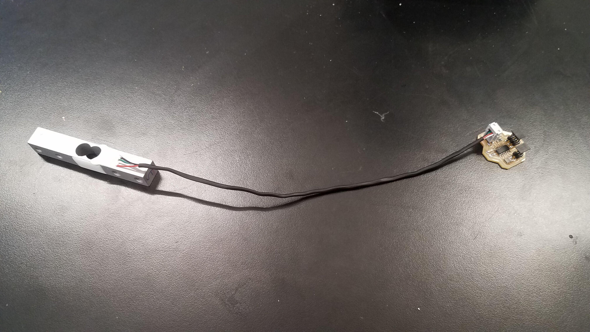
Networking these boards was a bit of a nightmare. Check out my week 10 documentation for all that entailed. I also worked on a board that utilized a 10kg load cell. I started by looking at Will Langford's 2015 page for help on that (and for help on making me feel very ashamed of the depth of my work. I highly recommend his page for that purpose, if needed). In the end, though, I didn't use any of his work.
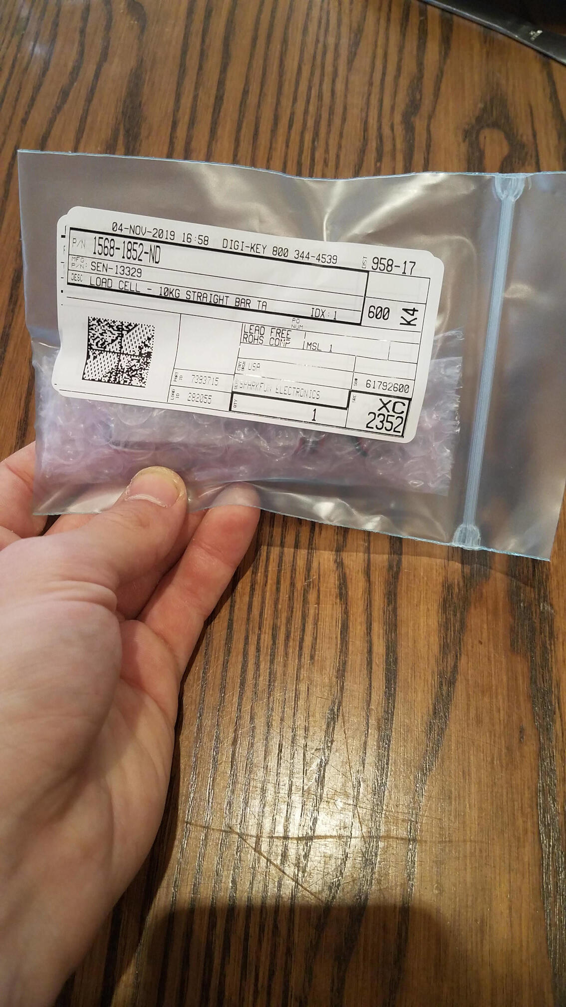
His implementation is for a high-res unipolar load cell. I was looking to have a bipolar load cell, but it doesn't need to have very high resolution. Given this, I just used the bipolar differential ADC on the ATtiny44. I used the 1.1V internal reference, and figured out a threshold using a serial connection. Read about that in week 12.
I connected everything up for a test, and it worked great! I was able to enter digits, and got a successful password match. On to the next!
Motion out of the mouth
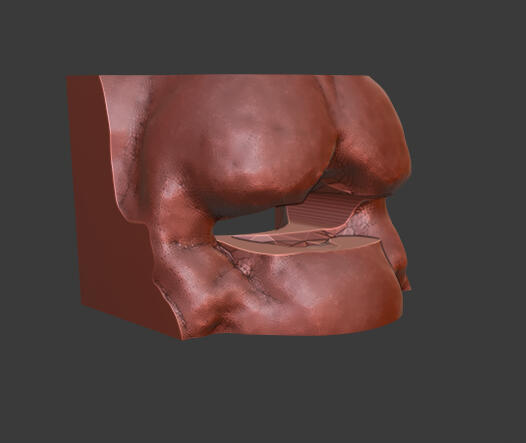
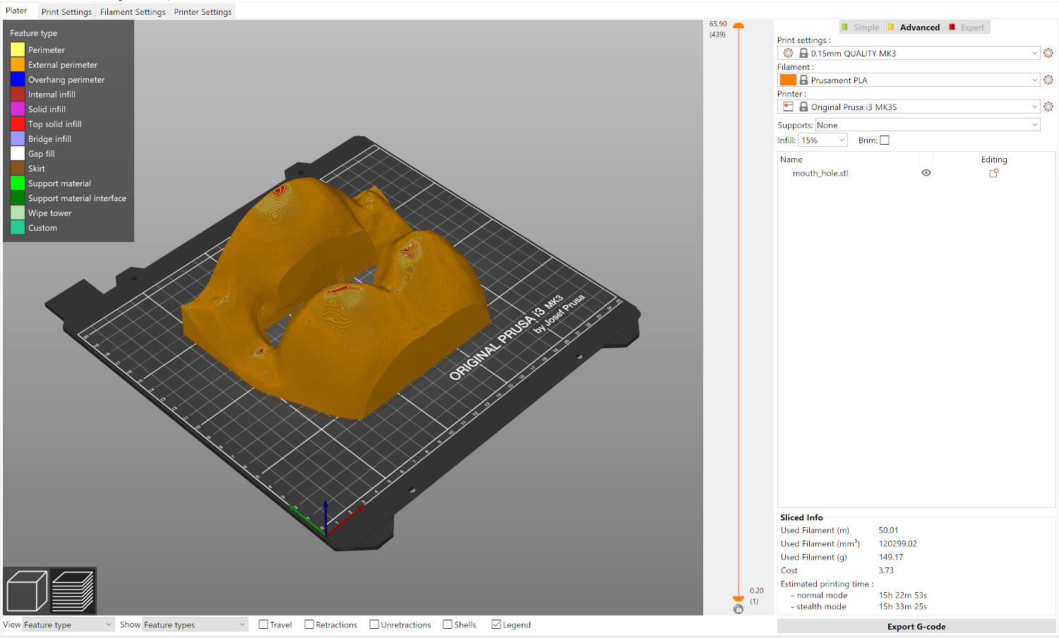
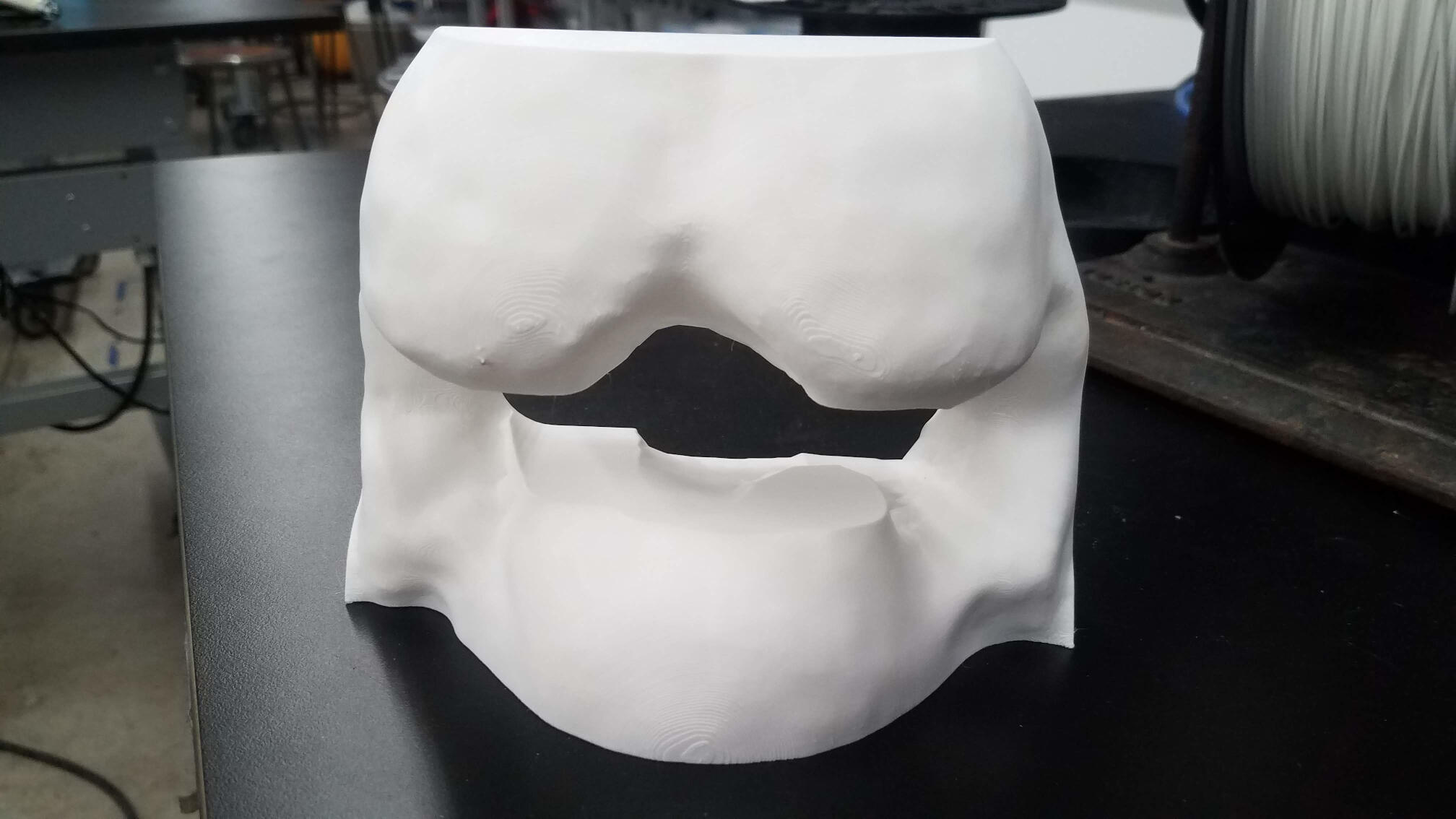
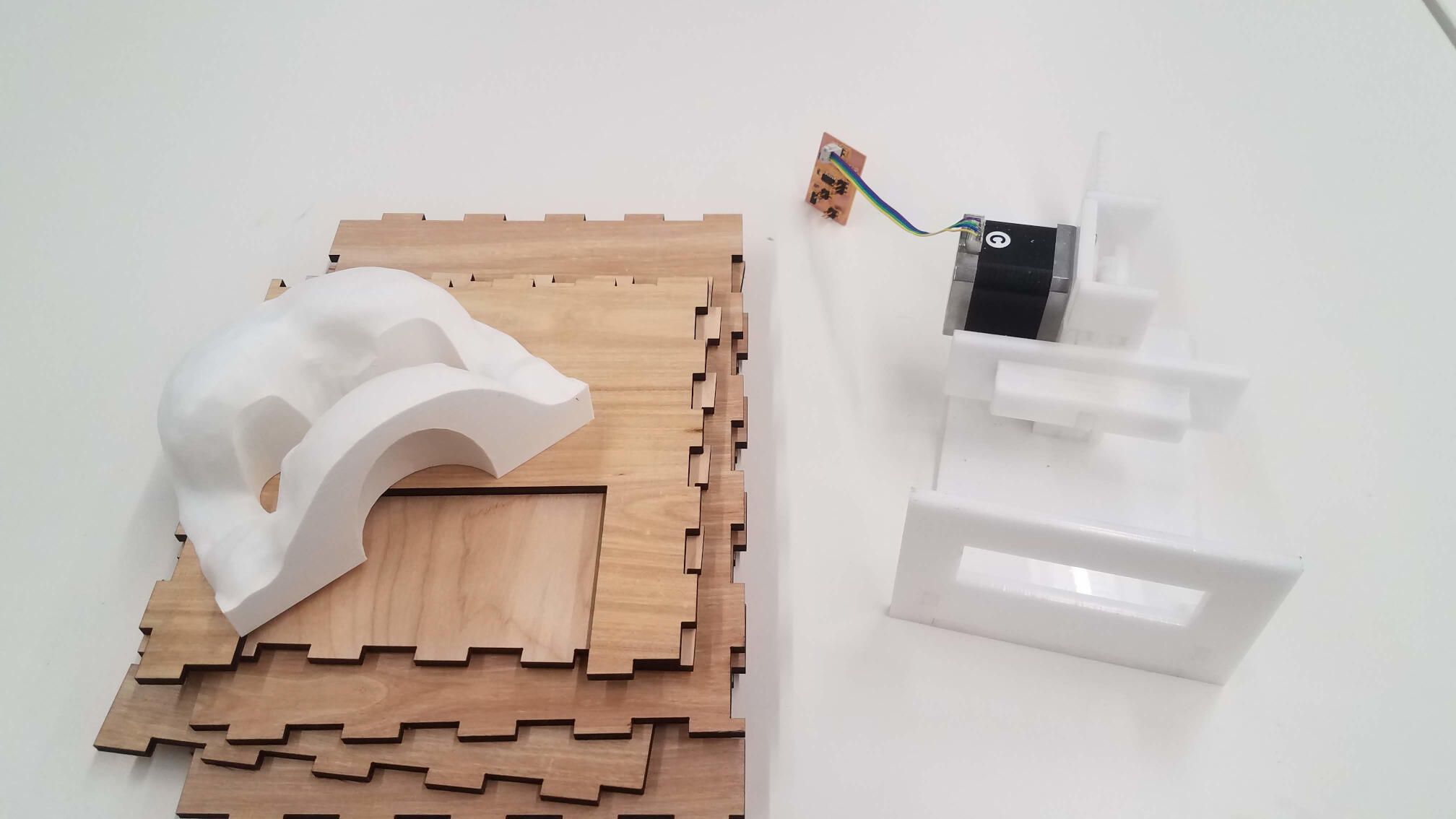
I was running a little short on time, so I decided to just take a small part of the mouth to have the box come out of. I used blender to pop a hole in the mouth of the lion model, and took a boolean and to get just a small cube of it. I imported it into PrusaSlicer and printed it in PLA on the Prusa Mk3S.
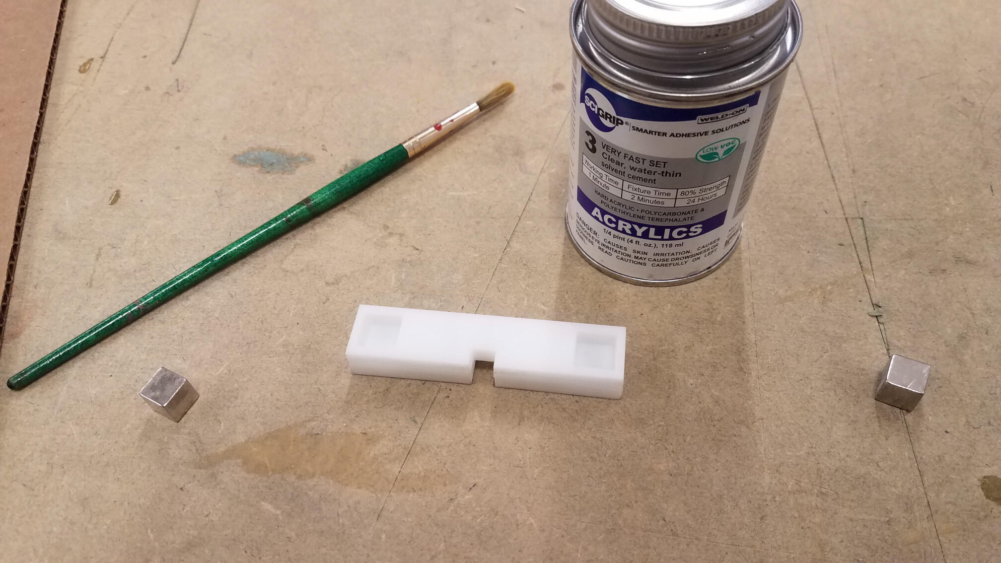
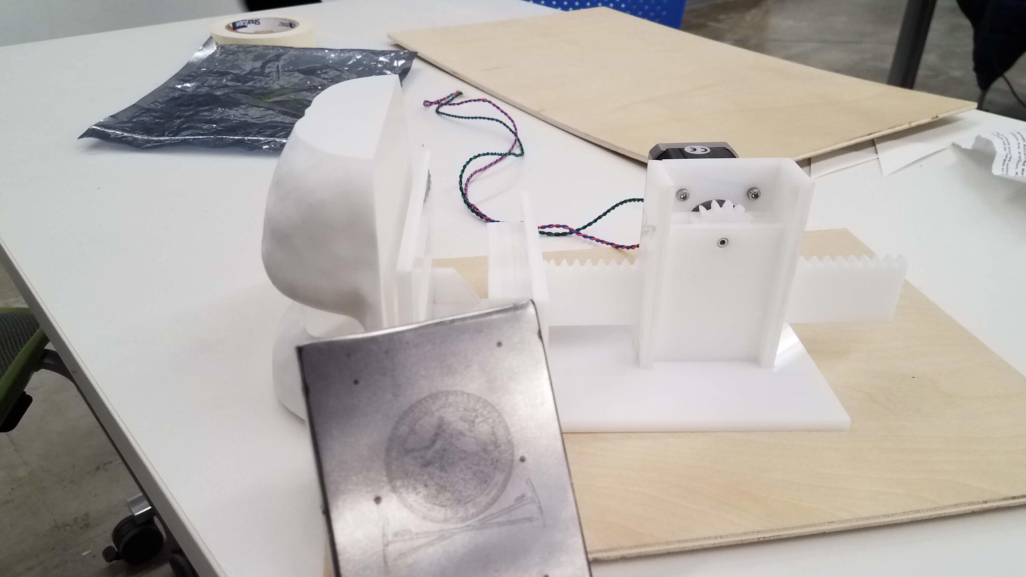
To get the box out of the mouth, I designed and laser cut a linear motion system (rack and pinion) that interfaces with a stepper motor. I used 6mm acrylic, and made it almost entirely press-fit. To connect with the box, I made the front a small rectangle with some cubic magnets sandwiched in a cavity between layers of acrylic. I aligned those with a slot in the rack, and then used acrylic cement to keep them firmly together.
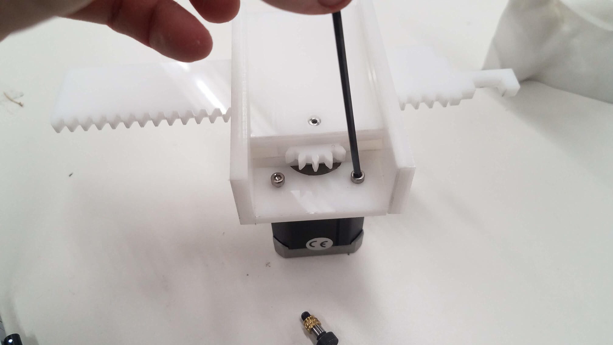
I remade Neil's stepper board with a connector to the rest of my system, and ran some tests on the linear motion of the system. After a WHILE of H bridge and cord errors, it worked amazingly! I got it to just move at all, and then move to the front and back of the range of motion.
Packaging
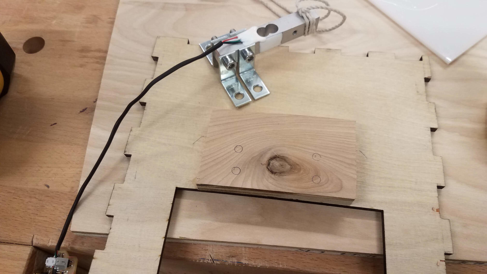
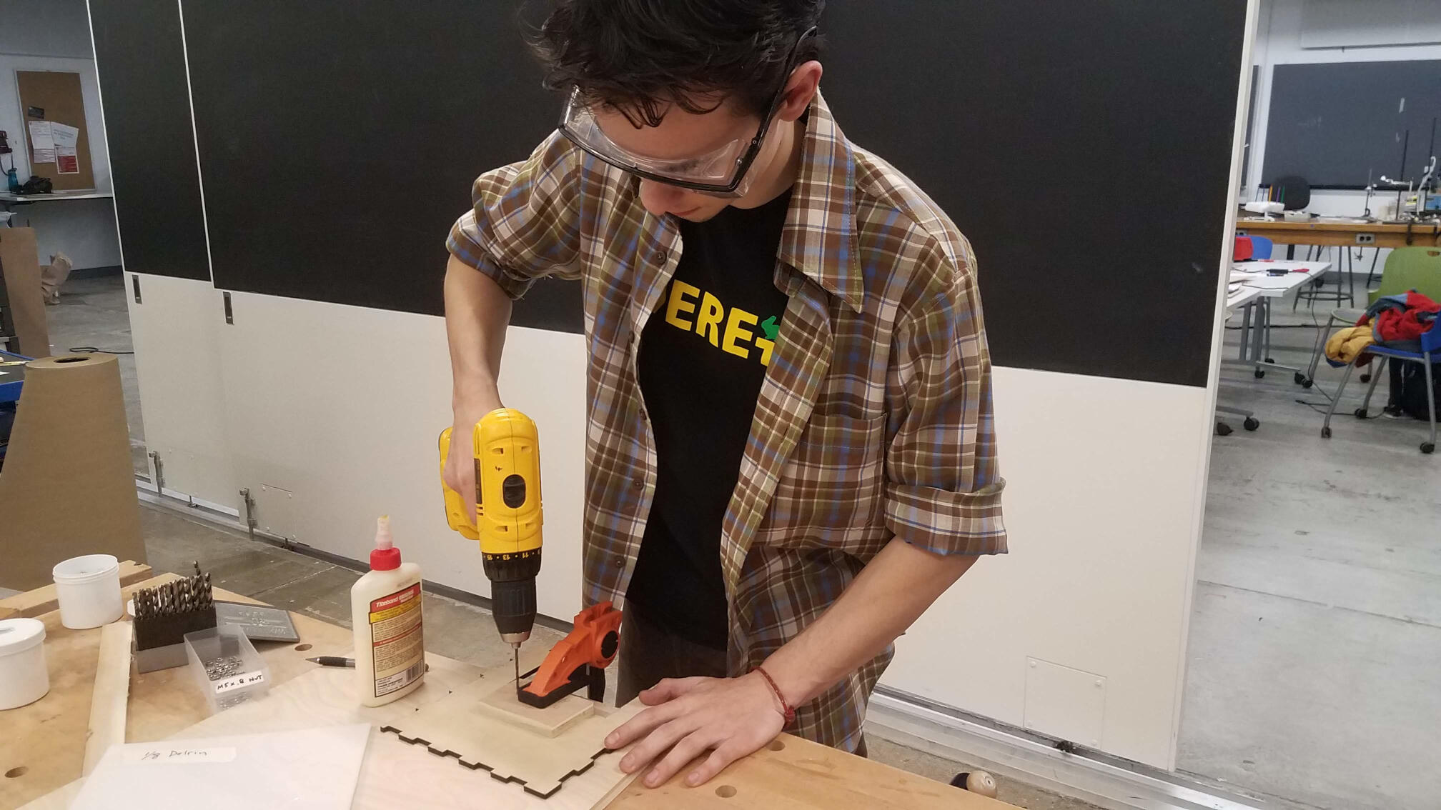
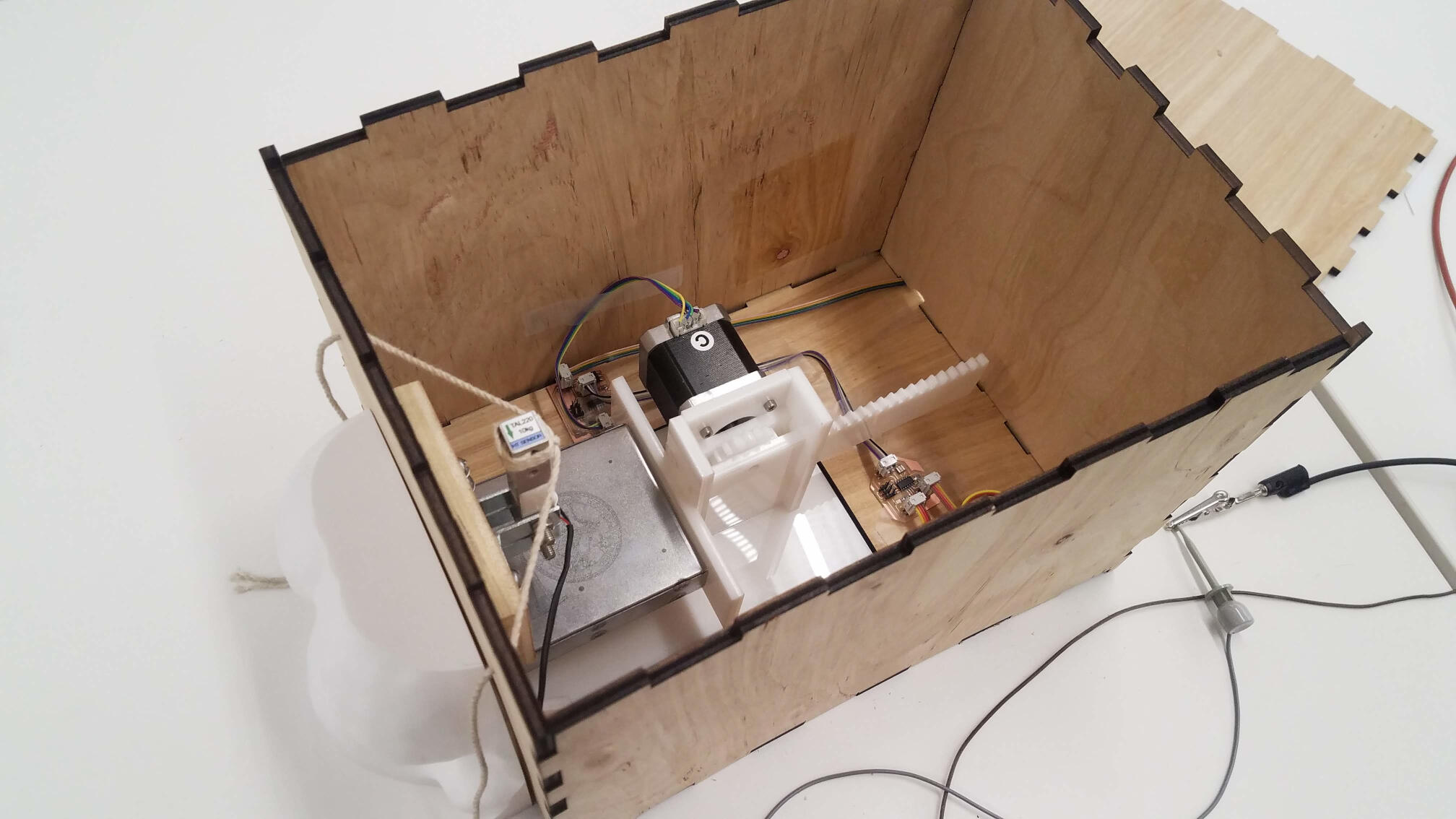
For the final packaging, I laser cut a press-fit (seeing a theme?) plywood box. I had to mount the load cell on the front inside of the box, so I used a thicker block of plywood attached with some wood glue and screws. I cut the block just on a jigsaw and drilled the holes by hand to fit L-brackets. The load cell had threaded M5 holes, so I just used M5x25 machine bolts with nuts to attach the load cell to those brackets.
I tied strings to the load cell and popped them through some more hand drilled holes. I attached everything else inside with... hot glue and scotch tape (the tape did a really good job with the piezo, but of course I wouldn't use it for a larger scale project). Everything fit in well, and I was ready to go!
---
Final video
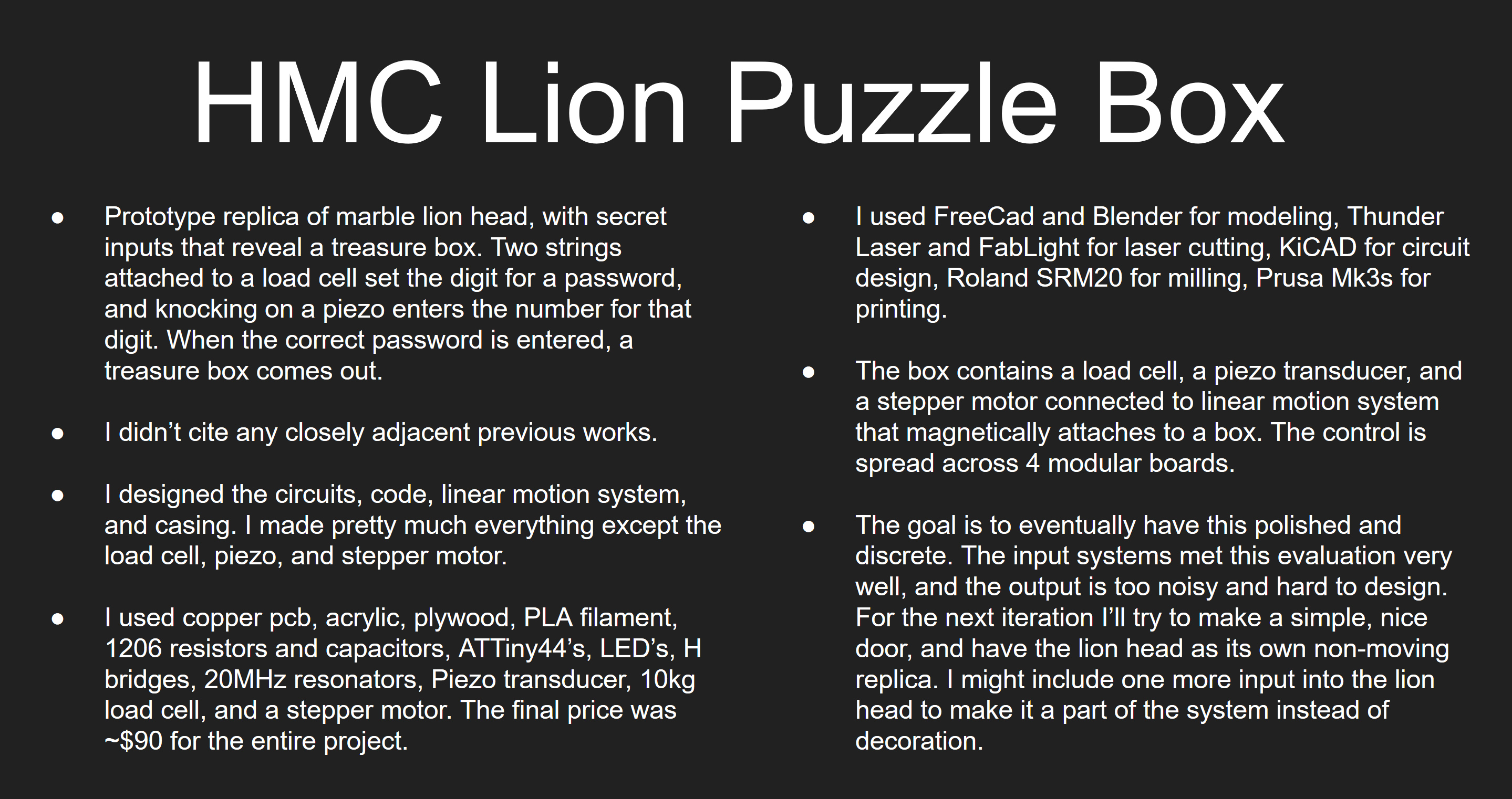
Summary slide
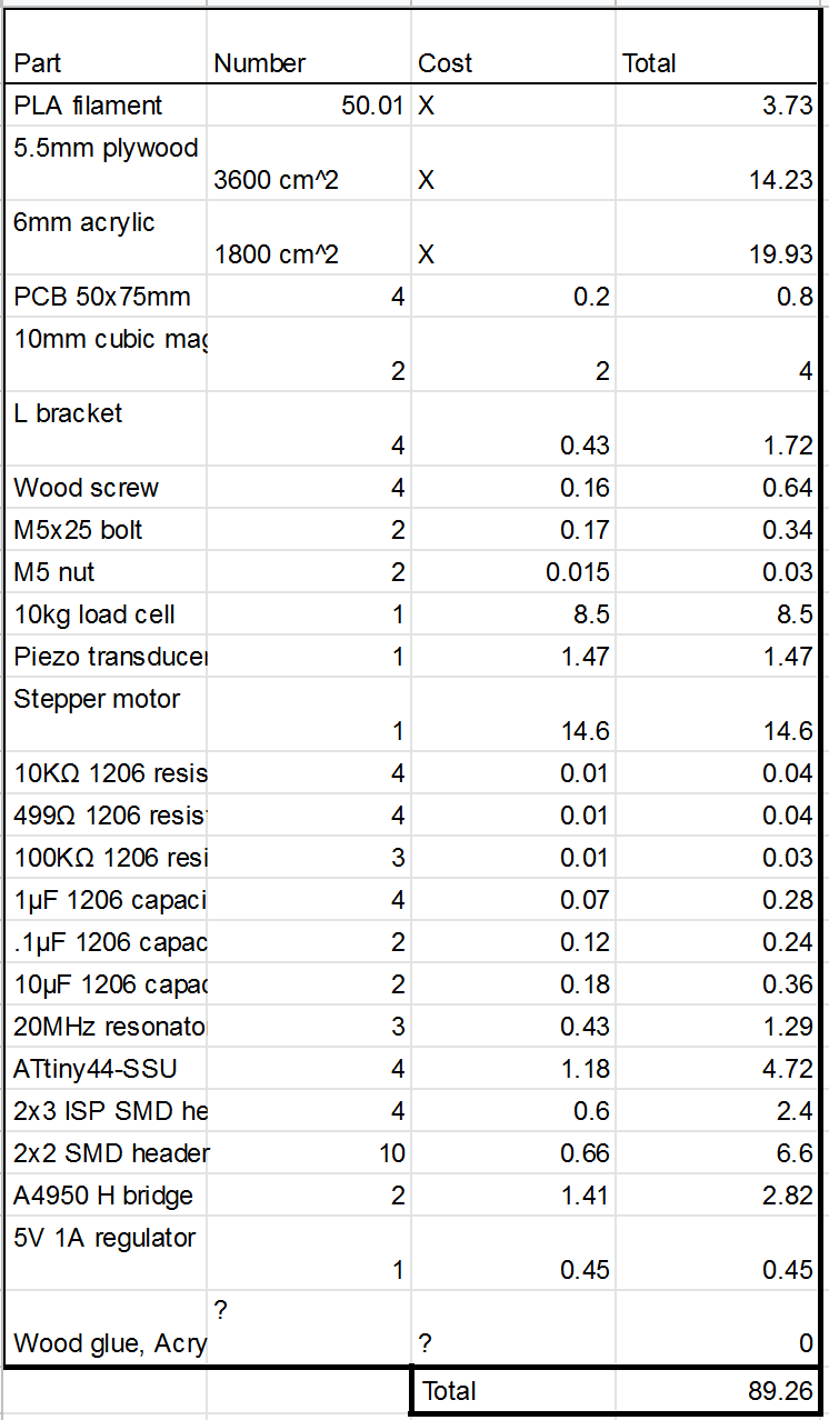
Pricing