FabECG: Open-Source Heart Rate Monitor
Fracchia and Marblestone
Description
-
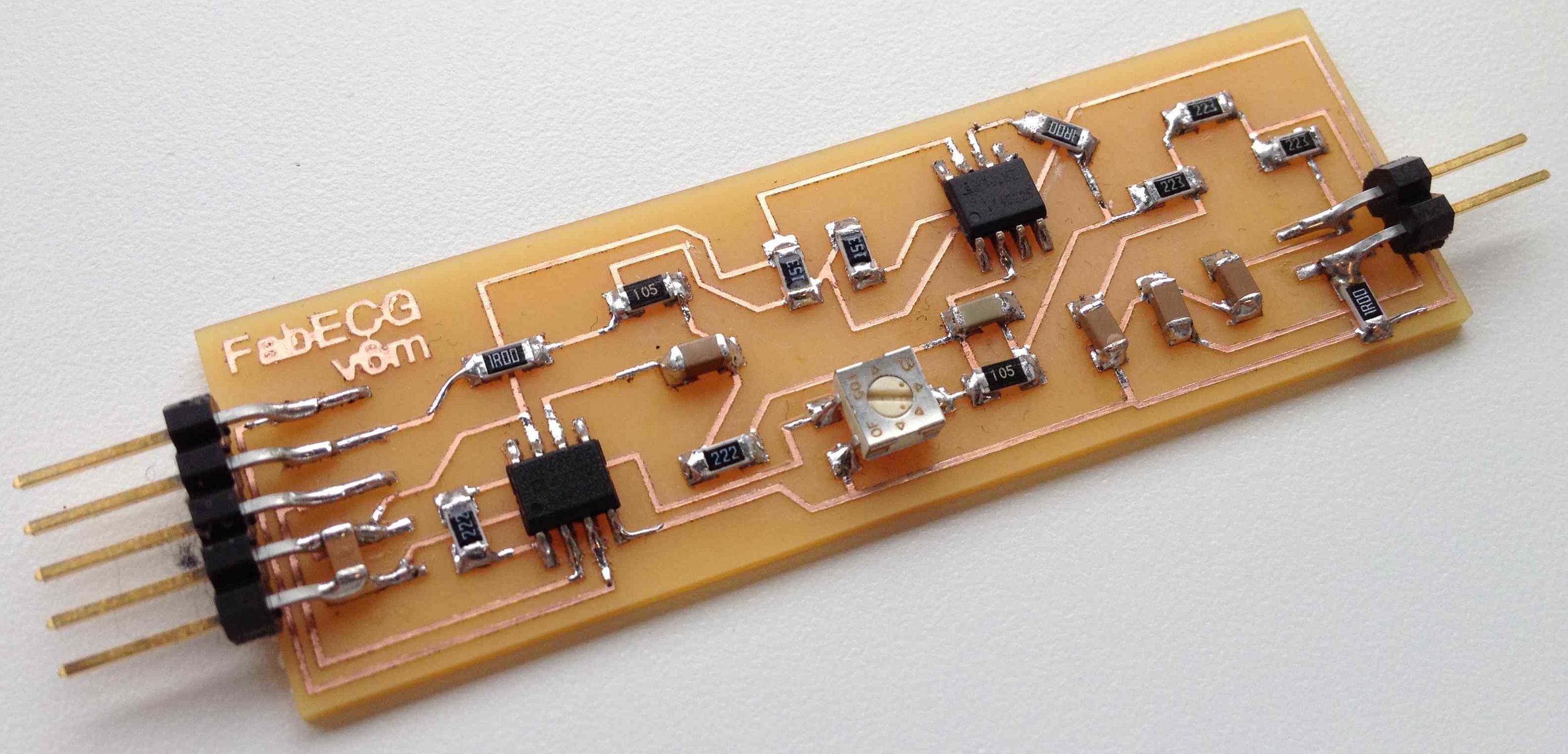
FabECG v6m
FabECG is an open-source ElectroCardioGraphy sensor board. In its current revision, the board allows up to 2 electrodes and a reference electrode. You can connect this board to an Arduino to collect your heart rate profile.
The board has currently an approximate footprint of 85mm x 22mm (3.5" x 1") with very sparse component placement. This is likely to shrink in size with future versions. The form-factor was chosen to fit inside the stem of custom vision glasses we are developing as a wearable sensor for high volume physiological data measurement. This is part of a collaboration between the Center for Bits and Atoms at MIT and Harvard Medical School.
Disclaimer: We make no claims about the safety of the below techniques or about their appropriateness for any purpose. Use at your own risk and consult experts on electronics safety. For example, you should not place the electrodes on your body if the power is supplied from a computer that is plugged in to mains!
Capabilities of the system
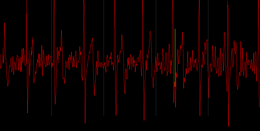
Using this system with a set of three fabric electrodes from a Zeo Sleep Monitor, we were able to observe heart rate by placing the electrodes on the user's chest, thumbs, throat and temples. We have also been able to see certain muscle activities when the electrodes were placed on the user's temples. We were able to record eye movements, blinking and swallowing motion.
Note: The following assessments are based on early testing of a protype and thus may not reflect accurately the full capabilities of the system.
-
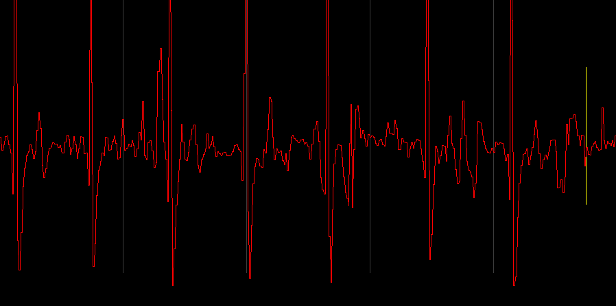
From Chest
-
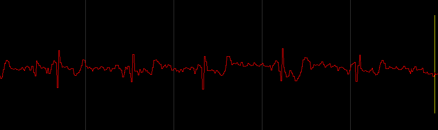
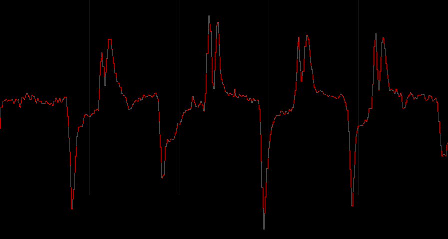
From Throat
-
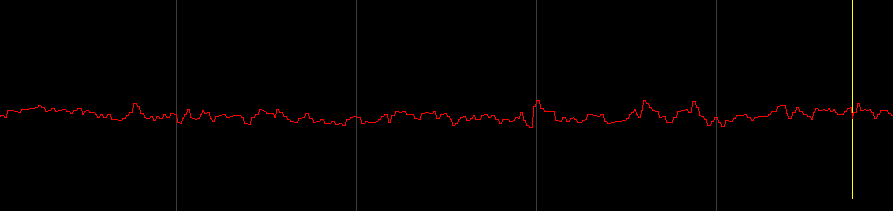
From Hand
-
Detecting blinking
-
Is there EEG there? :)
How to make it
Milling
We used a Modela MDX-20 from Roland with the open-source Fab Modules from the Center for Bits and Atoms at MIT to mill the board. Load the latest traces png file from the archive and cut them using a 1/64" mill. The default settings are changed by using the correct option in the dropdown from the Fab Modules program. Use a -1 value for the number of offsets when generating the path if you want a board that has only the traces left (like picture above). Use a 1/32" mill to cut the outline of the board by using the cutout png.
Soldering
| Name | Position | Reference |
|---|---|---|
| 0 Ohm Resistor | R1, R6 and R7 | link |
| 2.2k Ohm Resistor | R8 & RG | link |
| 15k Ohm Resistor | R2 & R3 | link |
| 25k Ohm Resistor | R9, R10 & R11 | link |
| 1M Ohm Resistor | R4 & R5 | link |
| 1M Potentiometer | Potentiometer | link |
| 6.8nF or 10nF Capacitor | C1 | link |
| 0.1uF Capacitor | C2 & C3: Bridging the 2 pins of the input connector (bottom left of board on v6m) | link |
| 220nF Capacitor | C7, C8 & C9 | link |
| AD620 Instrumentation Amplifier | Bottom Left IC (v6m) | link |
| CA3140 OpAmp | Top Right IC (v6m) | link |
Data collection and measurements
-
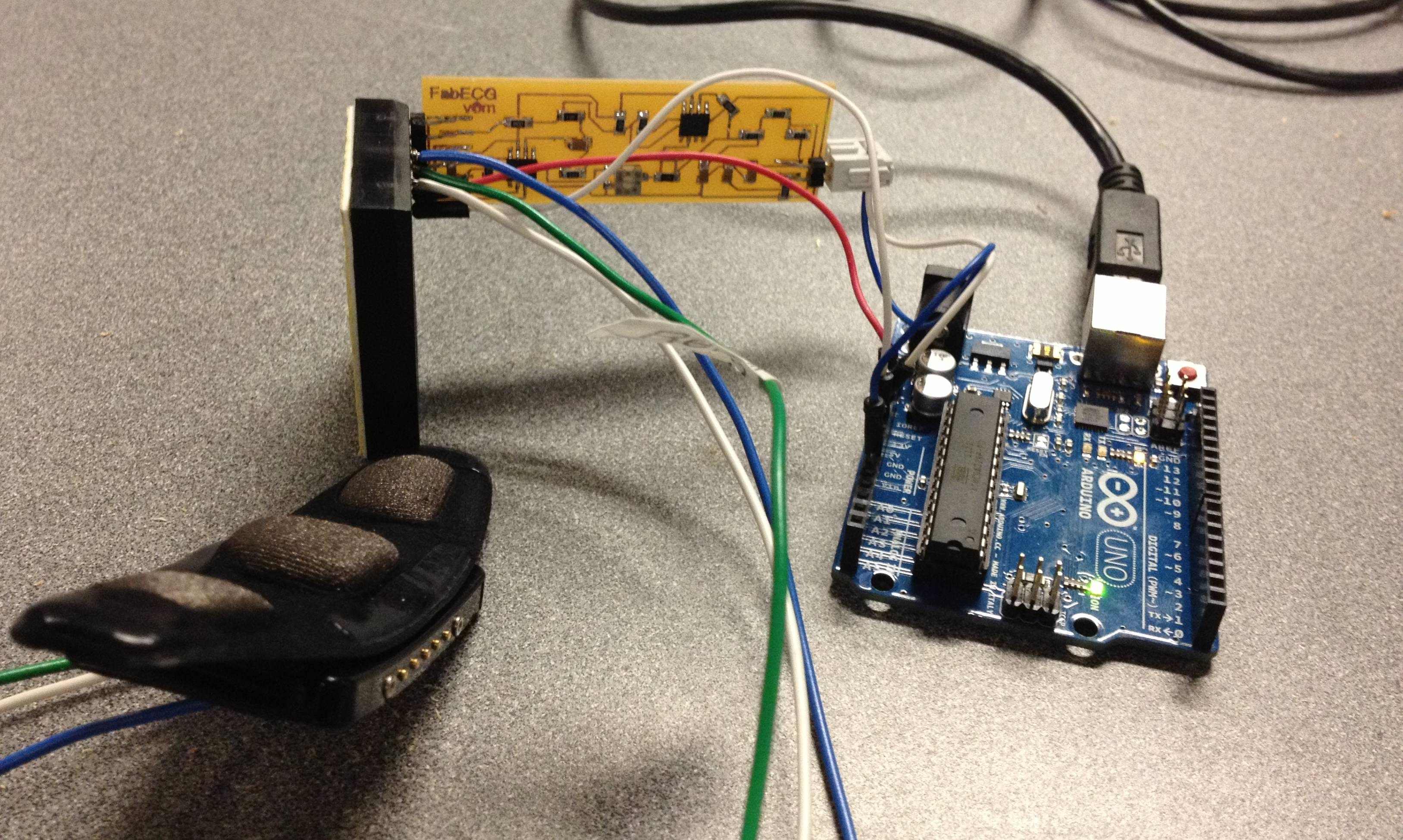
Measurement setup
Use the analog input of the arduino to sample the FabECG board. We will be sharing our software soon. Please bear with us as we prep for a release we're sure you'll enjoy :)
Design
Please use either the download or the GitHub links above to obtain the latest version of the EAGLE design files.
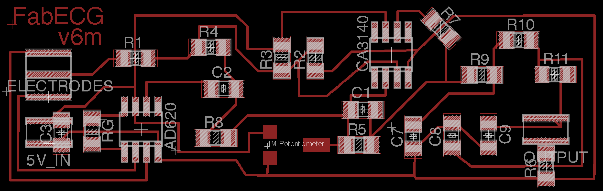
v6m is the latest version as of October 10th 2012. It doesn't include some indicator LEDs that are likely to be added in future
v5m is the last version with a double-sided board. It is not functional in its current state. It is likely missing a filtering capacitor on the CA3140 Voltage Follower feedback loop (see this thread).
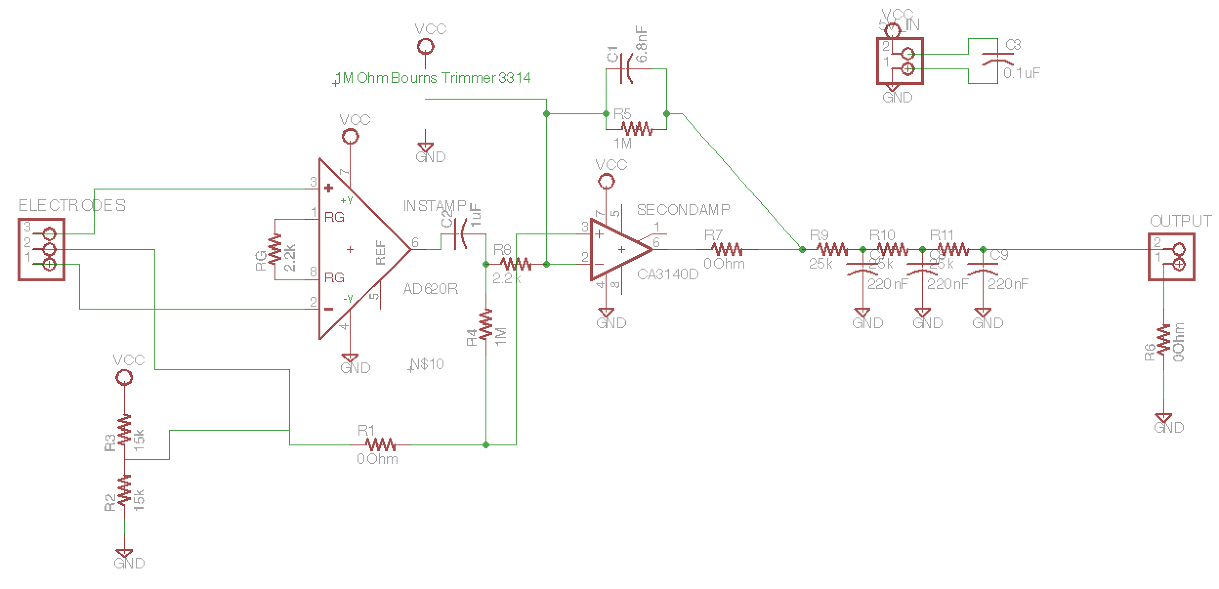
Below is the schematic for v6m of the FabECG board: