Week 10: Output Devices
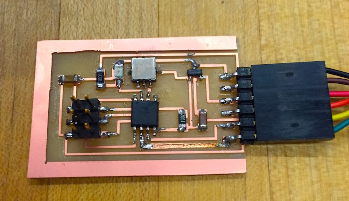
This week, I modified my board from last week such that it had one input device, an accelerometer, and one output device, an LED. I remove the 49K resistor and put in a 1K resistor, and replaced the photoresistor with a red LED.
The plan was to have the LED turn on when the accelerometer registered movement. I learned how to remove components with the copper braid and re-solder new components in place.
Edited Code
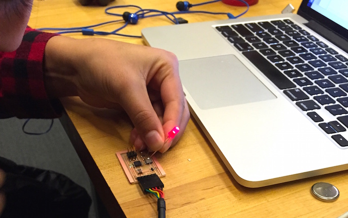
I needed to alter the C code to make the ATTiny44 into an output pin. I did this and encountered a bunch of errors. It turns out my LED was fried, so then I swaped it out for a through-hole LED for testing.

Running this code, I was able to see the LED turn on independantly of the accelerometer.

Turning on the LED
I am still debugging why this is the case. It seems to be an issue in my board design, not the soldering.
I then tried a totally different approach the next week (in conjunction with that week’s assignment). I made a Fabduino and programmed it to output: it blinked the on-board LED.

There is more about this and programming the other fabduinos in the next week’s writeup.