Week 9: Input Devices
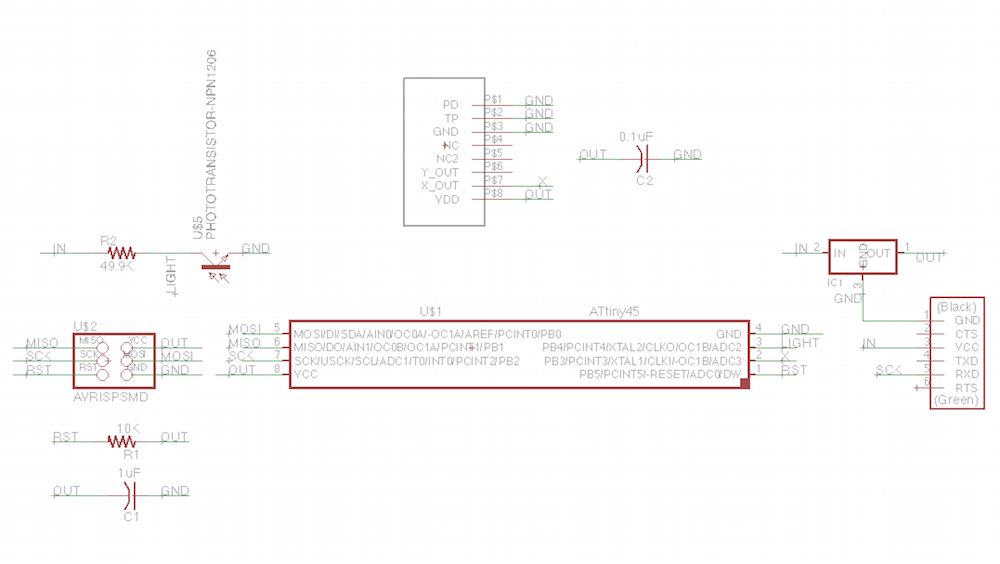
This week, I created a board that had two input devices, an accelerometer and a phototransistor. I first designed the board in Eagle based off of the light and 2-axis accelerometer boards shown in class. In the design of this board, I learned how to make a library for the MXD6235M accelerometer, since there was no Eagle library I could find online for the part. The new part is now in the class fab.lbr.
Schematic and Layout of the Board


Once I prepared the design, I cut the board on the Modela. This went pretty smoothly, except that one trace was destroyed. I used a piece of viynl-cut copper to replace the trace. I then stuffed the board. I will gloss over the details of this since it I talked about it in the “PCB Fabrication” writeup
The Stuffed Board

Now came the tricky part. Since I only used the X pinout from the MXD6235M accelerometer (ignoring the Y pinout), I needed to alter the C code and make a new makefile. My altered code can be found here.
I then re-compiled the make file and loaded it onto my board using the AVR programmer. Next, I modified the python file to show none of the Y coordinates. My altered code can be found here.
Running this code, I was able to see the X pinout of the accelerometer working.
Video of the Working Accelerometer
Next week, I plan to get the phototransistor working alongside the accelerometer.
Thanks to Dave Mellis for teaching me how to make a eagle library and Will Langford for help with debugging!