- 1.design and build the dome
- 2.design and build a bone conduction circuit that is embedded inside the dome
- 3.design and build a LED circuit that flashes according to the beat of the audio
- 4.design and build a vibration motor circuit that responds to the beat of the audio
- 5.eventually, instead of using an audio file, design a gesture-based instrument so that the hearing impaired users can also produce the music itself other than just listening to it.
- don't leave batteries attached to circuits! It doesn't matter if the circuit is running or not, it still consumes energy!
- start troubleshooting from the component that is easiest to assemble/disassemble
final project: music pavilion for the hearing impaired people
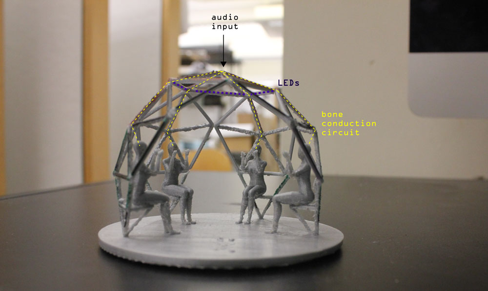
My final project was to create a setting where new channels of producing and perceiving music can be opened to engage the hearing impaired community more with the sonic experiences.
This page will only include details on the fabrication process of the pavilion. For details regarding the design itself, please refer to the final project idea page.

- Overall, since the project altogether was more ambitious than what is required by How to Make Almost Anything's final project which is a demonstration of the combination of different skills learned during the course (hopefully in an interesting way), I decided to break the project into sub goals:
I aimed to complete the first 4 steps in the framework of this course, yet despite my efforts on trying to understand the way H-bridge works, I managed to do only the first 3. More on the process is below:
Part1_Fabricating the elements for the geodesic dome structure
A.Dome's base
I decided to use metal tubes for the base of the dome because this is where the vibration motors were going to be placed and steel is great to intensify vibration
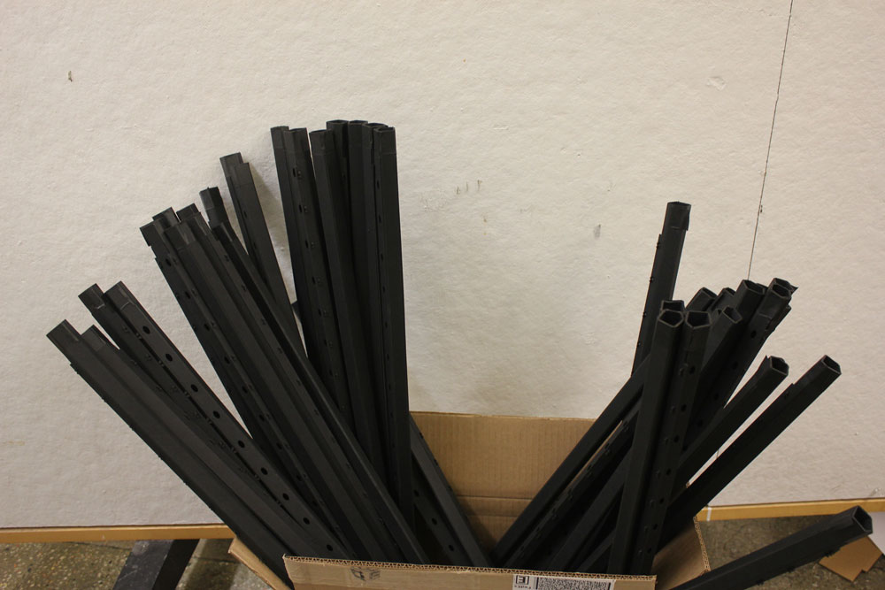
step1: buying the metal tubes
I bought 10 of this EMT conduit. Total cost was around $35 + I paid $10 for uber to carry them back to MIT.
step2:cutting the metal tubes

I used the metal chop saw for cutting the tubes into the dimensions I needed in N-51
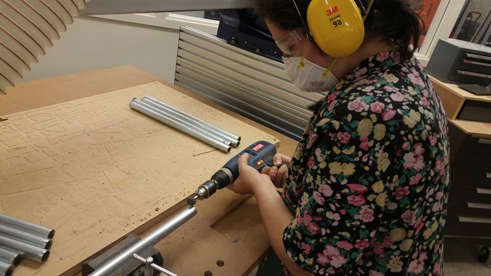
step3: grinding the edges of the metal tubes
after cutting the metal tubes, the ends needed grinding
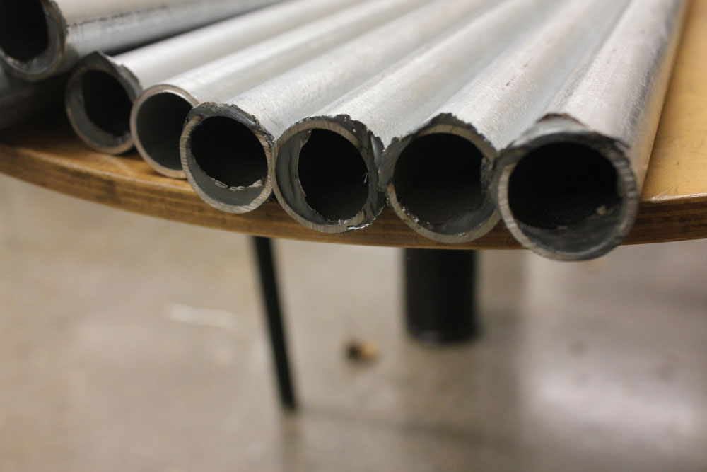
for half of the tubes, I used metal grinder at N51, and for the rest, used the drilling machine with a grinder end.
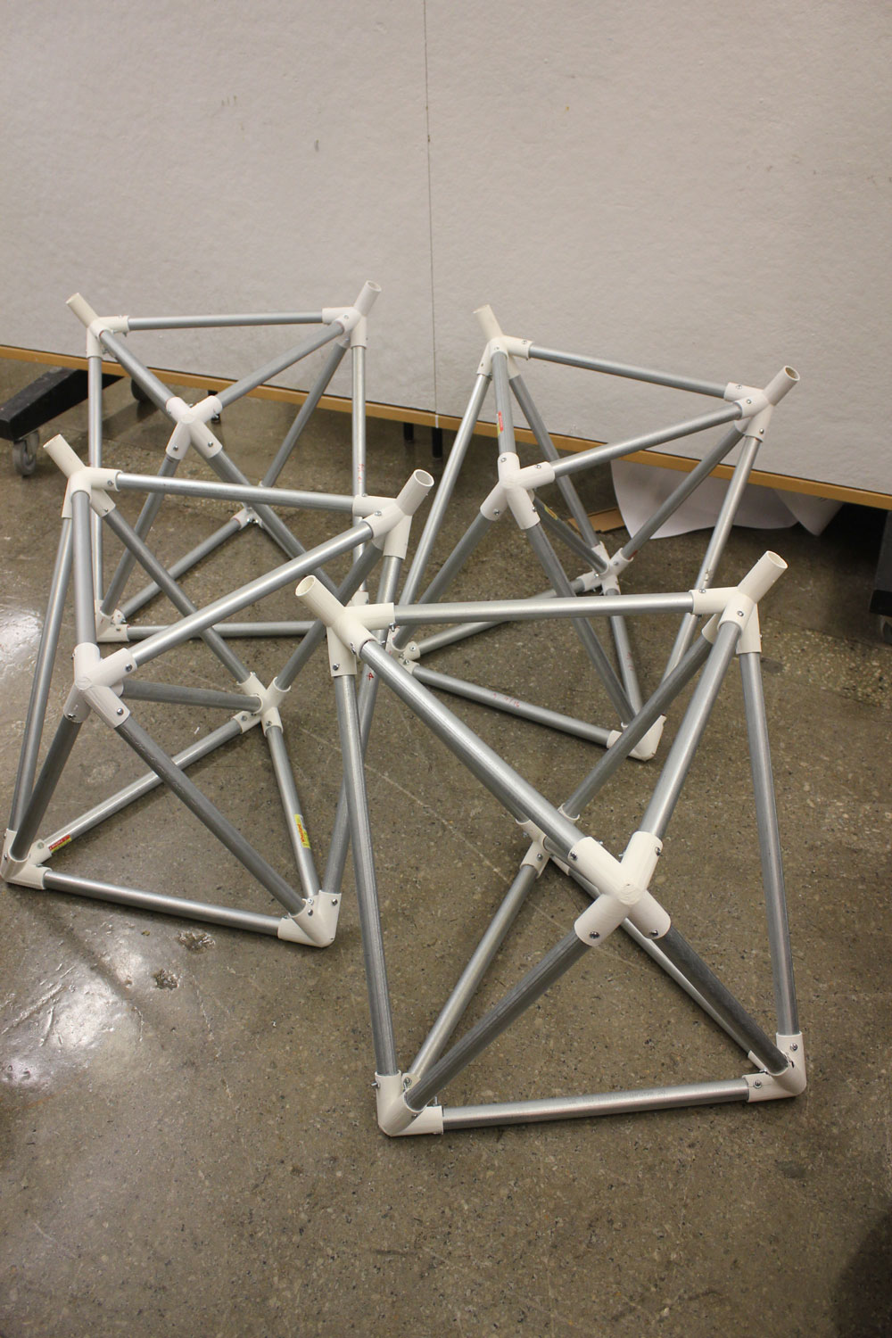
step4: bringing the tubes together to create the sitting elements of the dome
I assembled the tubes with nods that I produced during the 3D printing week
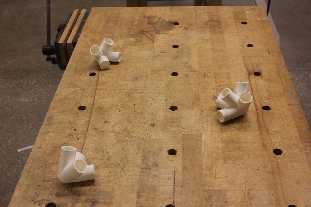


et voila!
B.Dome's struts
step1: buying the materials for struts
I decided to use 2 differet kind of material for the struts. One is a black museum board from BLICK, the other is polycarbonate sheet from McMasterCarr. I bought approximately 10 of the former (cost me around $100) and 4 of the latter (2 of 24x24" + 2 of 24x48"; cost me around $70). There was no shipping cost for polycarbonate sheets, uber cost me around $5 from Blick to MIT.
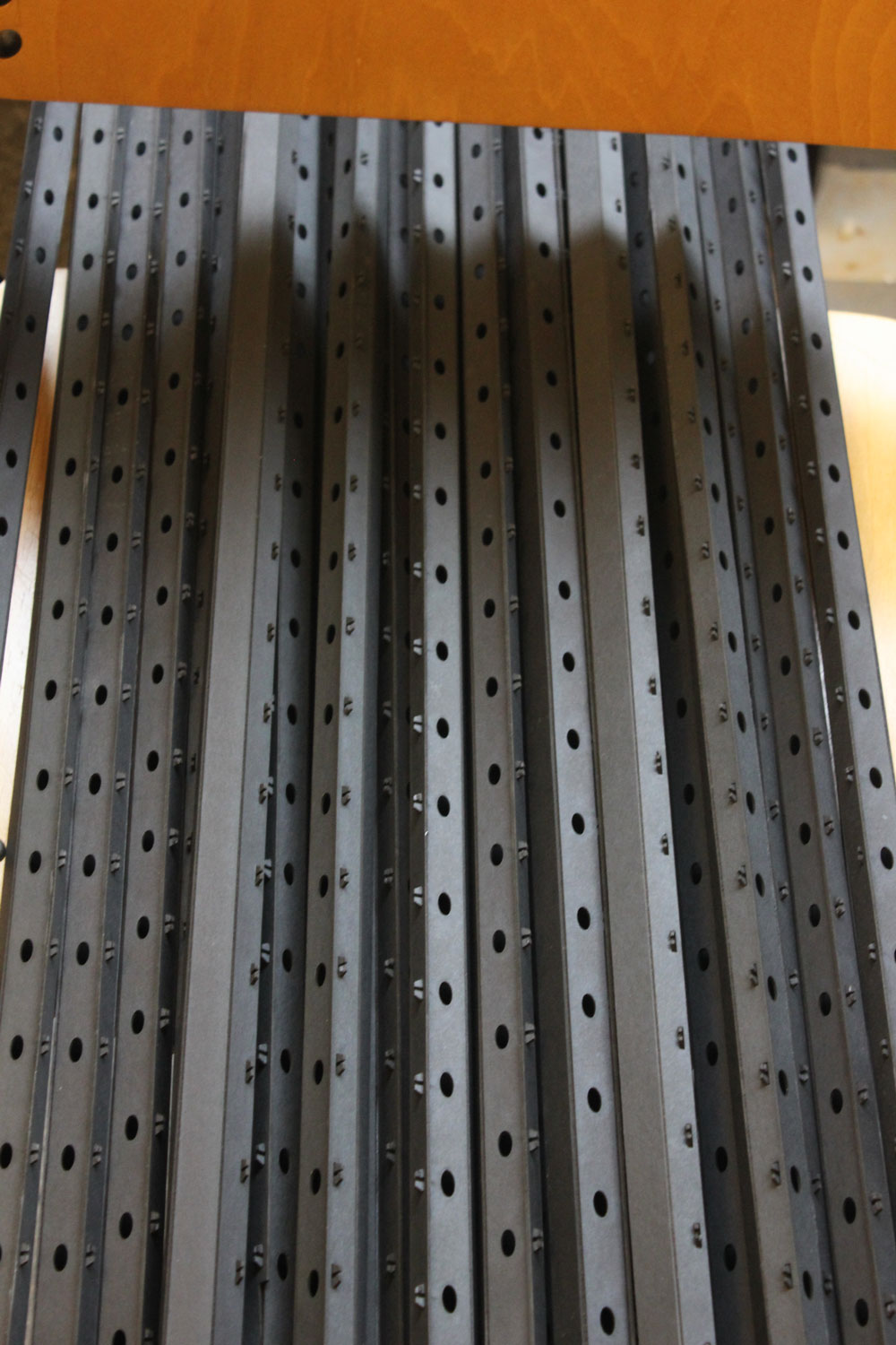
step2: making the cardboard press-fit struts
I've made the press fit struts by cutting & scoring & folding the material (laser cutter). Please refer to the computer controlled cutting week to find out in more details how to fabricate these!
step3: making the polycarbonate press-fit struts
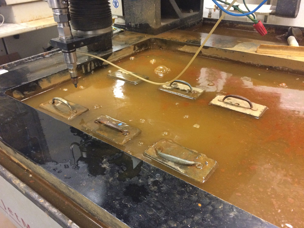
the main reason why I wanted to make some of the struts with polycarbonate (which is clear yet not brittle as acrylic and not non-structural like polyprophelyn or acetat) is to stick some LED circuitry into its surface with vinyl cutter. However with polycarbonate, since it's not possible to use the laser cutter due to the material's release of toxic smoke, the process was more tricky than it was with cardboard. I was only able to use waterjet cutter for this material with which the concept of scoring doesn't exist.
waterjet cutting the polycarbonate sheets

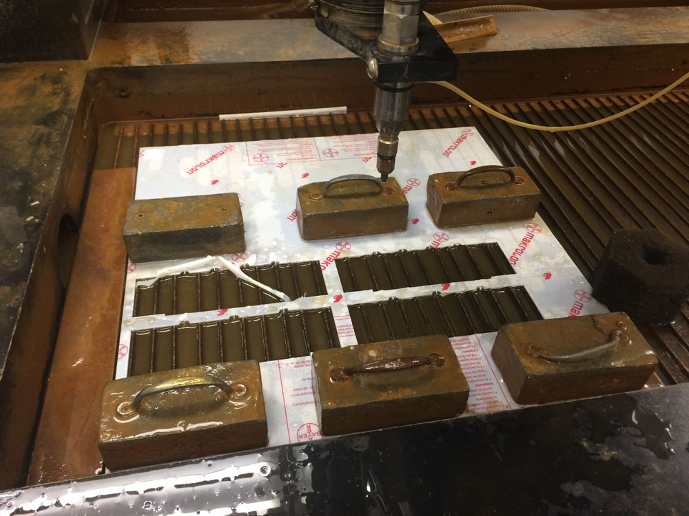

Scoring the pieces manually by using a mask, cutter and hot air gun
so, I designed and lasercut a mask which helped me score the pieces neatly by hand
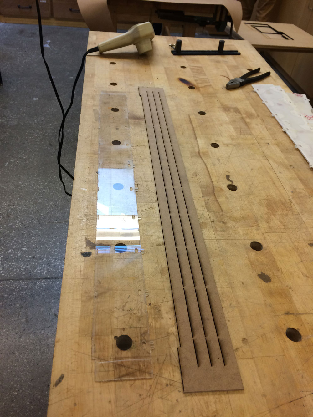
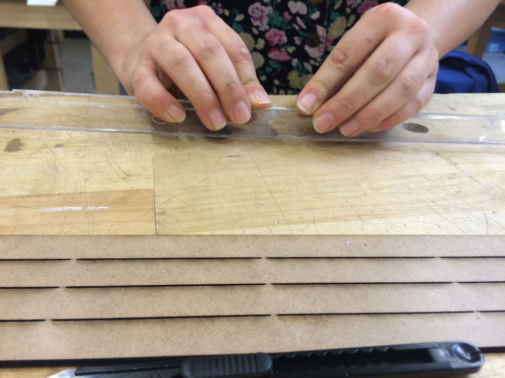
after placing the mask on top of the waterjet cut polycarbonate piece, I clamped them to the desk to prevent layers from sliding.
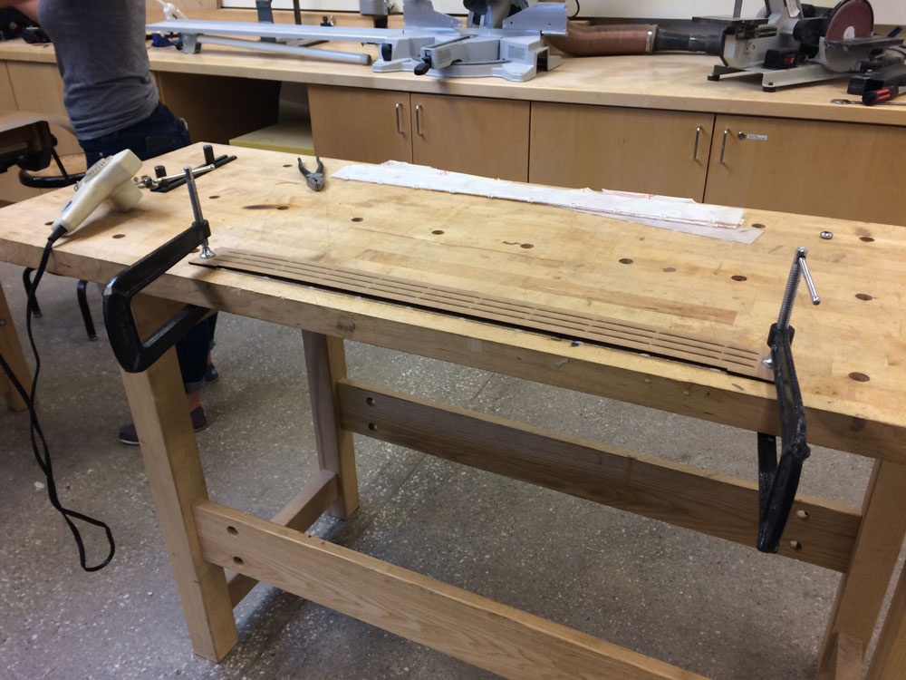
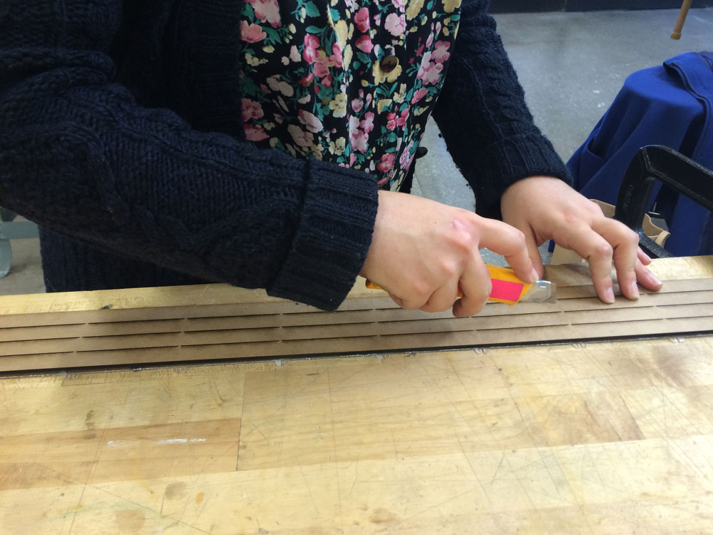
then scored the polycarbonate carefully with a cutter. The mask helped me make sure that the lines were perfectly straight!
then, by applying heat to the fold lines, I increased the material's elasticity which helped me fold it easily.

et voila!
Part2_Producing the electronics of the dome
A.Bone conduction
the exact process of bone conduction amplifier circuit design can be found in the output devices week.
step 1: deciding on the amplifier's gain
I made 3 different iterations (gain:20, gain:50, gain:200) of my amplification board for bone conduction circuit. Used the datasheet for LM386:

gain 200
I connected a capacitor (20uf) between the pins 1 and 8 of the chip (LM386)


gain 50
I connected a capacitor (20uf) and a resistor(1.2 k ohm) between the pins 1 and 8 of the chip (LM386)


gain 20
pins 1 and 8 of the chip are disconnected


finally, I decided on using the gain:20 one since the sound was the most clear in this circuit.
step 2: fabricating 4 amplifier circuits
milling a PCB and soldering companents to it is now a well known story!

B.Beat reflective lights embedded on a clear strut
after vibrating the skull to create the sound within ones cochlea, I wanted to have a visual feedback as well as a tactile one. For the latter, I would need a vibration motor circuit and I decided to postpone it for future updates of this project since simply there was not enough time. However I decided to try the former.
step 1: design & fabricate a small section of a LED strip for the proof of concept
homemade LED strip trace:

tracing copper sheets with vinyl cutter, trying different force intensities:

sticking them into a polycarbonate strut's surface and populating the circuit with LEDs and resistors:

step 2: connect the circuit to the beat detection system (arduino + processing)
Having made my own circuit for the core electronic part that was bone conduction, I decided to use an arduino duemilanove that I made during input devices week for the light addition. The programming environment was Arduino IDE and Processing (through running the standard firmata). I basically used the adapted version of my code from the interface programming week for beat detection on processing.
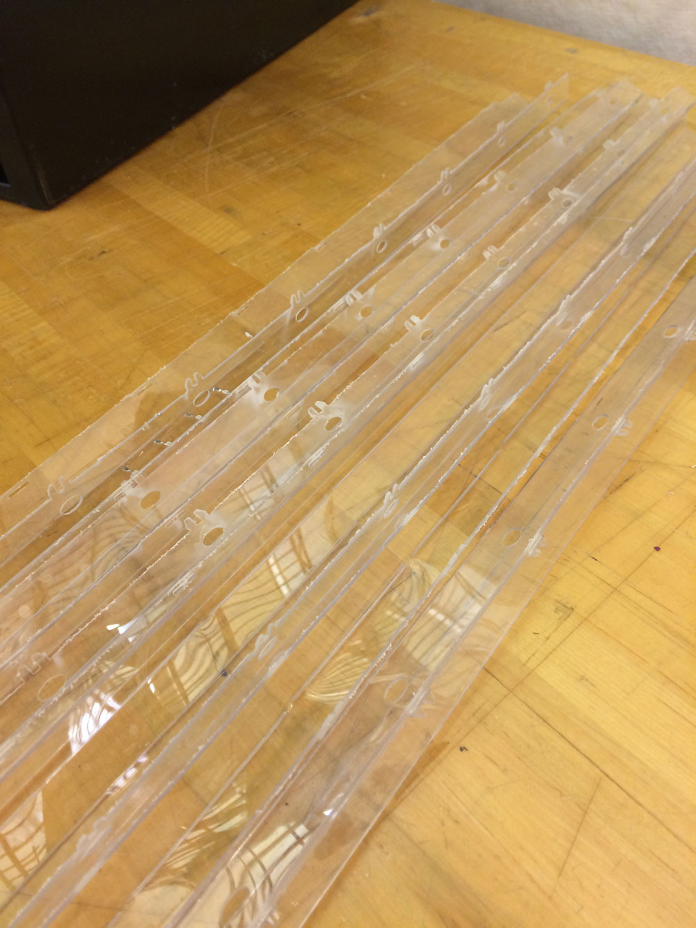
step 3: actually fabricating 3 homemade LED strip embedded clear polycarbonate struts
After successing in the "proof of concept", I decided to fabricate LED homemade LED strips for the lenght of at least 3 polycarbonate struts since I was separating the beats into 3 channels thru Processing. The main reason why I wanted to do my own LED strip by using a ton of LEDs and copper stickers is because I find the commercial LED strips super kitch. So, for the sake of being able to end up with exactly what I wanti I spent painstaking hours for the vinyl cutting of the copper, sticking the copper bands into the polycarbonate surface and soldering the resistors + LEDs into it. Ugh!!!

after vinyl cutting more copper bands, I started placing them onto the struts' surfaces

then I soldered the resistors and LEDs

all looked pretty good, so I decided to try each strut with the actual beam detection current. Video below is a timelapse of my trouble shooting session.
all done! now it was time to snap close the strut and articulate it to the structure!

C.Forehead band: interface between the bone conduction devices and the skull bones
step 1: sewing velcro into elastic band
I bought 2 rolls of elastic band and a one roll of velcro. After cutting them into desired lenghts by making sure that they will be adjustable to different head diameters, I needed to sew the velcro into the elastic strap.

I had never used a sewing machine before but I learned how to use it pretty quickly. I was way faster compare to sewing by hand.Before using velcro and elastic band, I made some trials on a scrap textile.
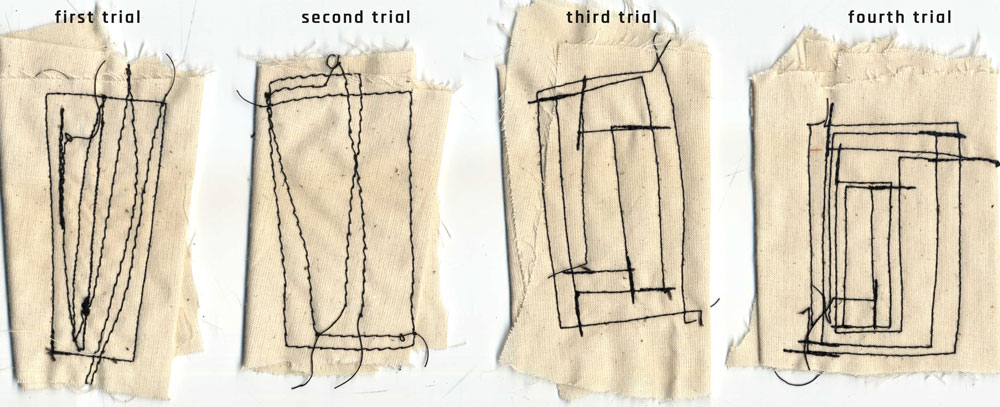
Of, course I got it jammed couple of times but this problem can easily be solved by pulling the mingled thread out of the bobin repository (make sure to higher the needle before to not to break it!)

et voila!

finally all the velcro bands were sewed into the elastic band.
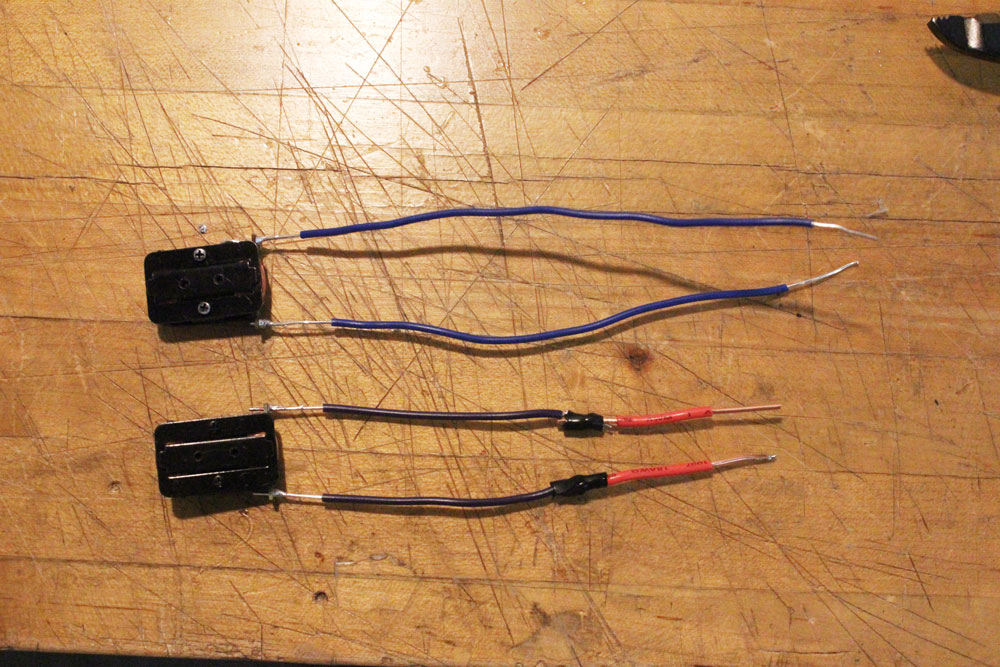
step 2: sewing bone conduction devices into the forehead band

now it was time to sew the bone conduction devices into the head band. I did that by hand since it required lots of attention.

now only thing I had to do was to solder the ground and VCC cables to the bone conduction device during the final assembly of the dome.
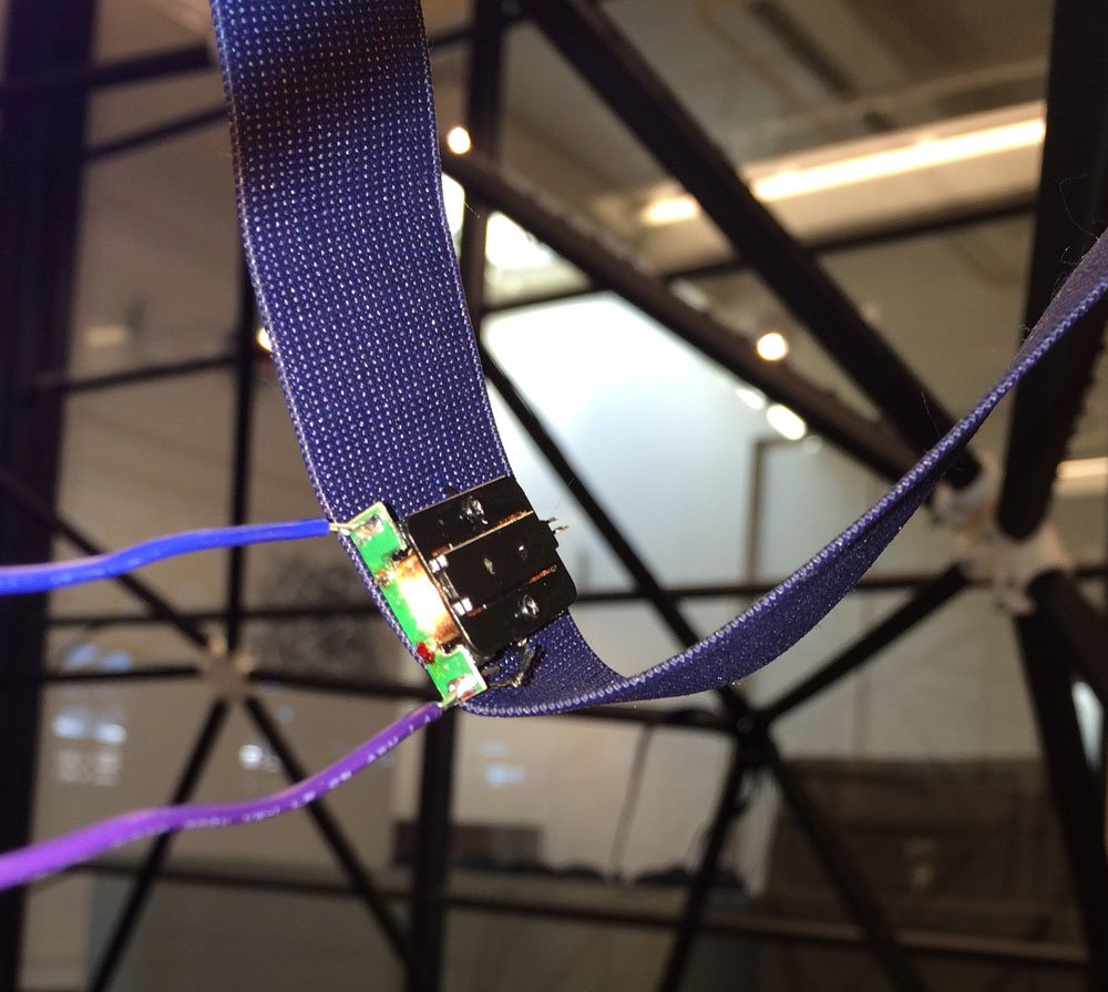
et voila!

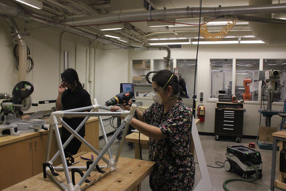
Part3_Final integration and the set up of the dome
so far, it had been very challenging to come to this final phase. I appreciate to the truth in the illustration below:

The metal bases of the dome: check!
The black carton and clear polycarbonate struts: check!
Bone conduction amplifiers (4 of them!): check!
Adjustable forehead bands to interface the bone conduction devices to the skull: ckeck!
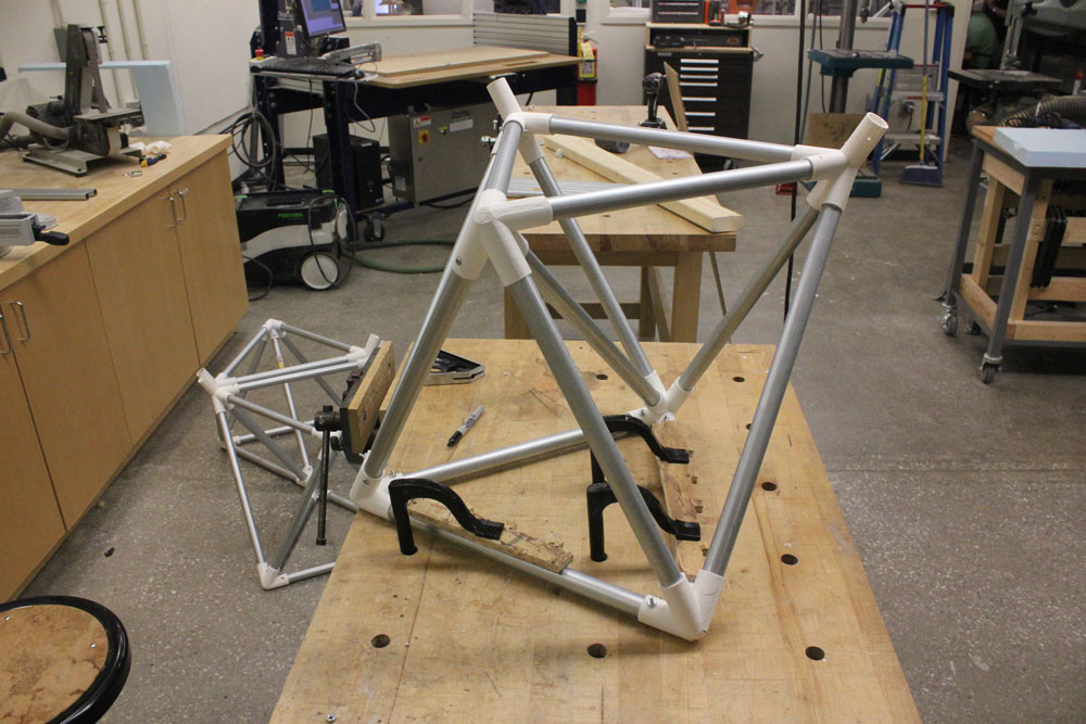
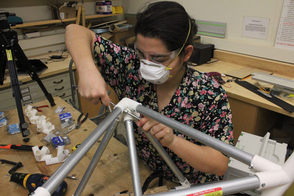
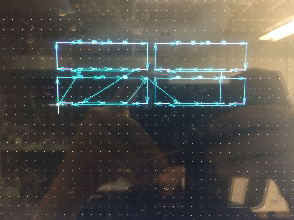
I have started with marking the decagon projection marking the edges of the horizonral struts. This reference is important to be able to know where to put the metal bases.

After placing the metal bases, I started articulating the black carton struts to them.


Then articulated the black carton struts to black carton struts.


even though the assebly theoretically looks fairly easy, it actually requires quite an effort since making holes in every branch of the connecting nodes is a painstaking process!

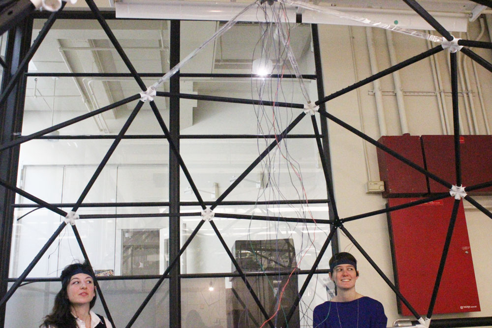
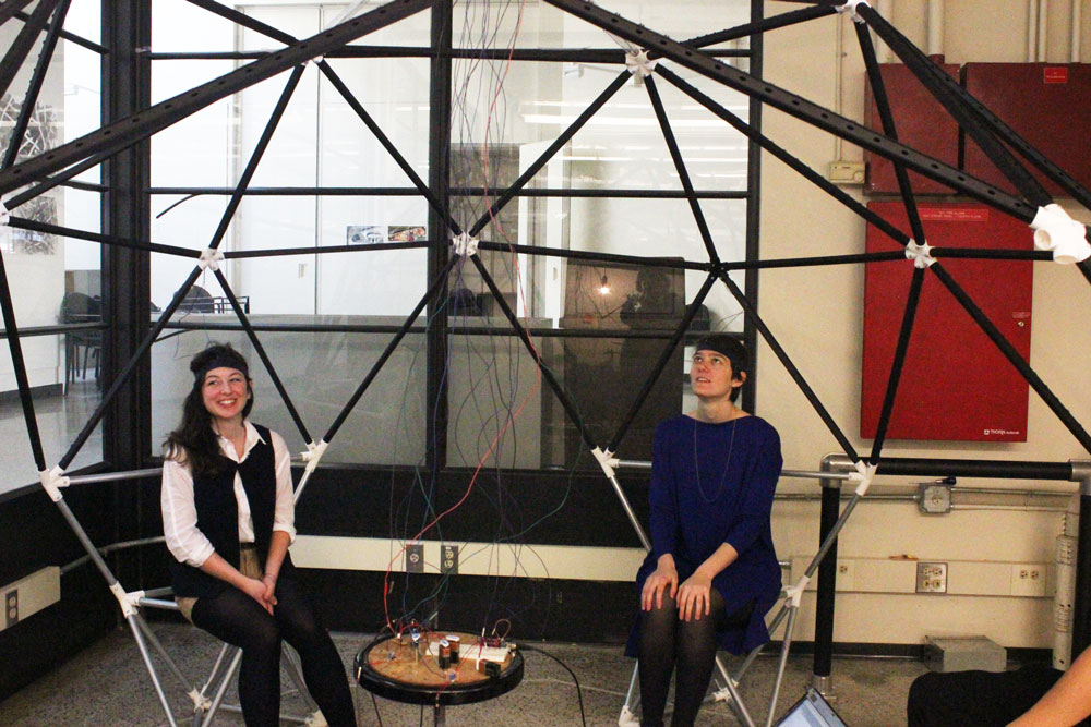
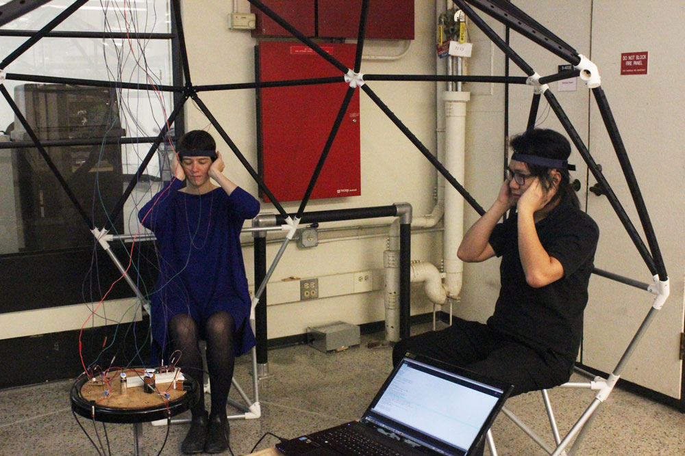
When all the struts were articulated, it was time to stretch the electric cables across them. The aim was to distribute sound (via an amplifier) from the sound source in the middle (for now, it's a computer; at the end of the Spring semester, it will be a gesture controlled instrument!) to the each bone conduction devide embedded in a forehead band worn by an individual sitting on the metal base.

The reason why there are thousand cables is because I need 2 currents (ground abd VCC) for each LED strip embedded polycarbonate strut (there are 3 in total) and 2 currents (ground and VCC) for each bone conduction device (4 in total). Below, how the source is looking like:

all connections were made and everything was ready.
pressed the play button. nothing happened.

troubleshooting!
disconnected all the amplifier circuits and checked the connections with a multimeter before desoldering anything. All looked (in fact, sounded) fine!
then I thought maybe the fact that I have articulated small sectioned and large sectioned cables together creates some sort of disconnection (even though they seem to conduct fine). I had no concrete reason to believe so, but I still decided to make an experiment where I attached the 2 bone conduction devices to 2 different well-working amplifier circuits. while doing so for some reason I changed the batteries powering the circuits as well. Both bone conduction devices were working equally fine! Then I put the old batteries and saw that the bone conduction devices were not working. It was interesting because the "old" batteries were not in fact old, they were not used since I haven't played music with the system more than 10 minutes in total but they were always attached even if the music wasn't playing. It turned out that even if you don't use your circuit to do what it does (in my case it amplifies sound), if you leave batteries attached to it , it still consumes power!!! That was mind blowing for me. I checked all the batteries originally attached to the circuits and saw that they were diminished to 2-3 volts from 9 volts even if the amplifiers were not in use. That taught me 2 things:
Number 2 was especially a painfully learned lesson for me! I had desoldered the circuits from the system to check the connections with a multimeter and desoldered bone conduction devices to try them with cables with different lenghts articulated together. however, all I needed to do was to unhook batteries from the clips, check the remaining voltage with a multimeter and put new ones back on!
lessons had learned and all the connections were working now!

and it was time to demo!


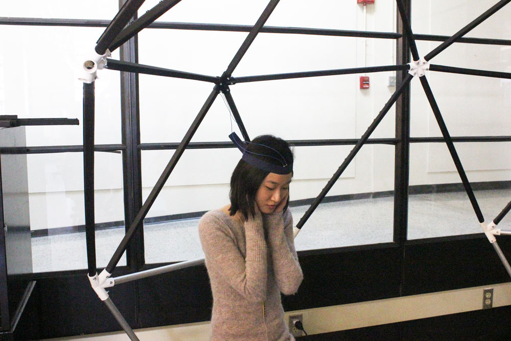
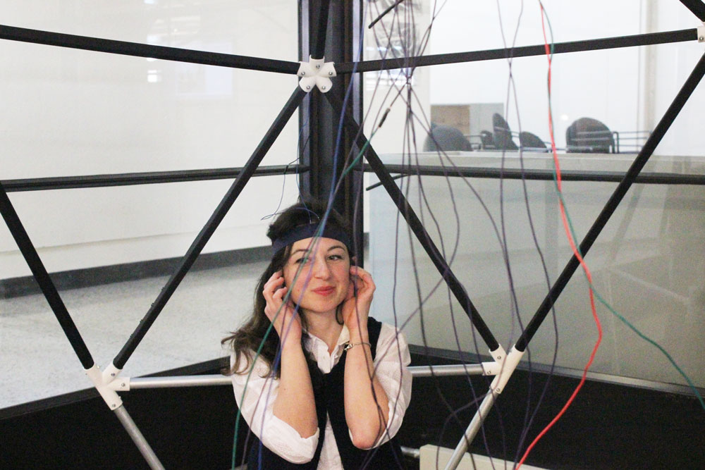


I told the users to plug their ears wittheir fingers to enhance the bone conduction effect!