Final Project (IDEAS + Workflow)

IDEAS: Deciding on an idea for my final project was such a hard thing to do. Mainly because there are so many things that I am always curious about and would like to make. So, after many ideas and sketches, I decided that I wanted to make something to solve a problem I face in my daily life, while being of interest, of course. So, I made a chart of what my intersts are, and another chart of possible problems/ inconveniences I usually encounter within those certains interests.
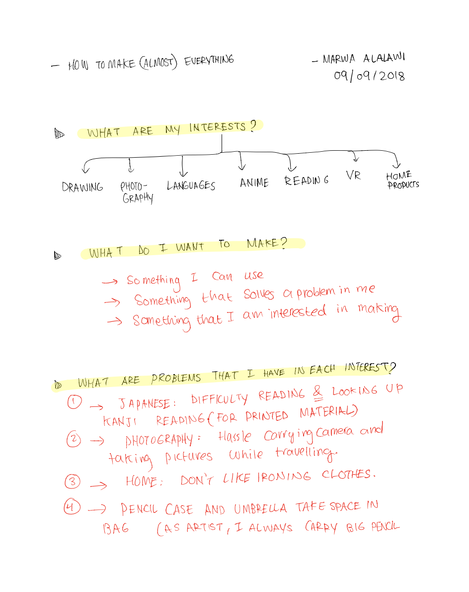
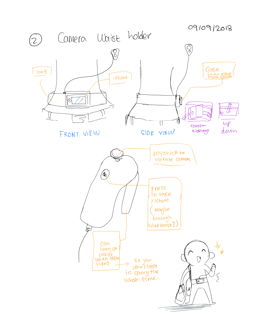
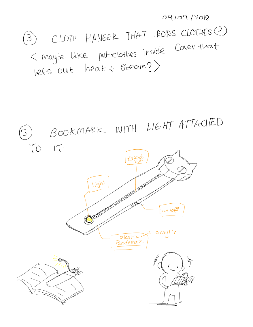
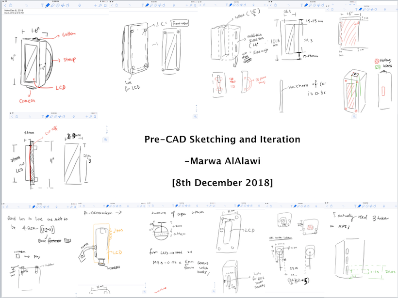
As a good starting point, I drew very rough sketches of "potential ways" I could solve these problems

I love learning languages! I speak four languages in total, and Japanese is one of them. Japanese is a very unique language compared to other langugaes in that it uses three sets of alphabets, or "writing systems" depending on the origin of the word. The three sets are: Hiragana (for native Japanese words), Katakana (for words imported from other languages), and Kanji --Chinese characters used in combination with Hiragana to give insight to word meaning. Any student of the Japanese language won't have problems memorizing Hiragana and Katakana as both are easy to read, are 46 characters each, and don't change in pronunciation according to the word they appear in. Kanji, on the other hand is 2,000 + characters that change in pronunciation according to word. Because I love reading Japanese novels, it is always daunting for me to go and look up the pronunciation or meaning of a certain kanji character or combination when I come across one I don't know. On top of that, keyboards that support kanji characters for typing only work when the pronunciation of the kanji is known-- which is not ideal for my case.
The only two availiable "time-consuming" technologies are either using the google translate application to take a picture of the text,and highlight the kanji you want to read. But this method doesn't give the reading, and instead simply gives the English translation. The other alternative is to use the iphone's chinese keyboard to write (with your finger) the kanji character, then look it up online or in a Japanese dictionary. However, sometimes the kanji writing could have multiple strokes and be overly complicated, that a user, like me, won't be successful in inputing.
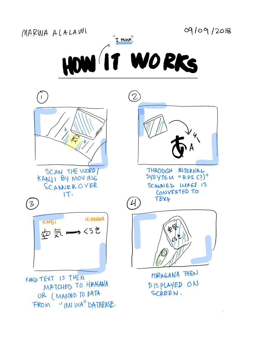
So, long story short, to solve this pressing problem, my idea for my final project is: a scanning pen for Kanji characters! .
The pen works by having a scanner at its tip, where you scan the word. Then, through OCR (Optical Character Recognition), the image is transformed to text, and matched to the correct reading of the word in Hiragana.
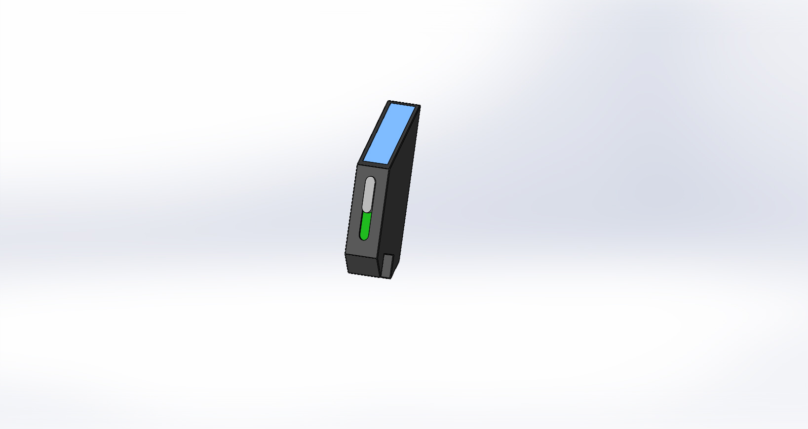
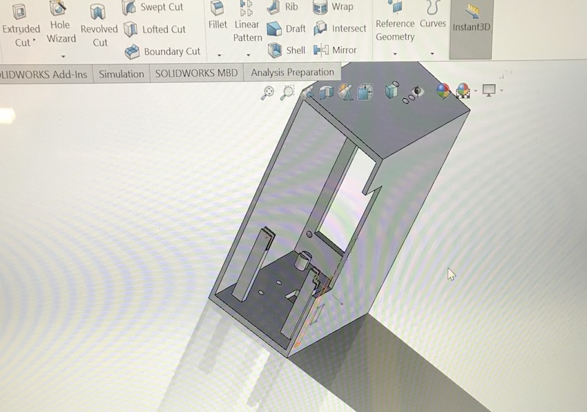
To model this final project, I made a prelimeinary iteration using Solidworks of how the pen would look like. I like using solidworks because as a mechanical engineer, it is a platform that I am used to. It's inteface can be a bit confusing at first, but watching a couple of tutorials can help, and is definitely worth it! :)
Coding: OCR and Databases
OCRS: By searching for some open source Optical Character Recognition platforms, I came across "Tesserect". I am currently fiddling with it to see how well it can detect Japanese text.
Tesserect: To get Tesseract working on my computer, I followed the instructions mentiond on its Github, which can be found here. Because I am using a mac, I did all the installation through Homebrew. It is very straightforward, so just follow the steps outlined on the Github page.
I also downloaded the "tessdata" for Japanese and vertical Japanese (because vertical Japanese is what novels use), and added them to the tessdata folder within the main tesseract folder.Since I needed to do a quick prototype to check how good Tesseract is at detecting characters, mainly Japanese Kanji characters, I used the example xcode that comes with the mac version of Tesseract. I first tested on English, and noticed that it was accurate for translating computer screenshot text images into actual text. However, I noticed that it wasn't very accurate when it came to handwritten text, which I tested by taking screenshots of my own handwriting. Useful Note, to know where the tessdata is added or tesseract is type "brew list tesseract" to see that.
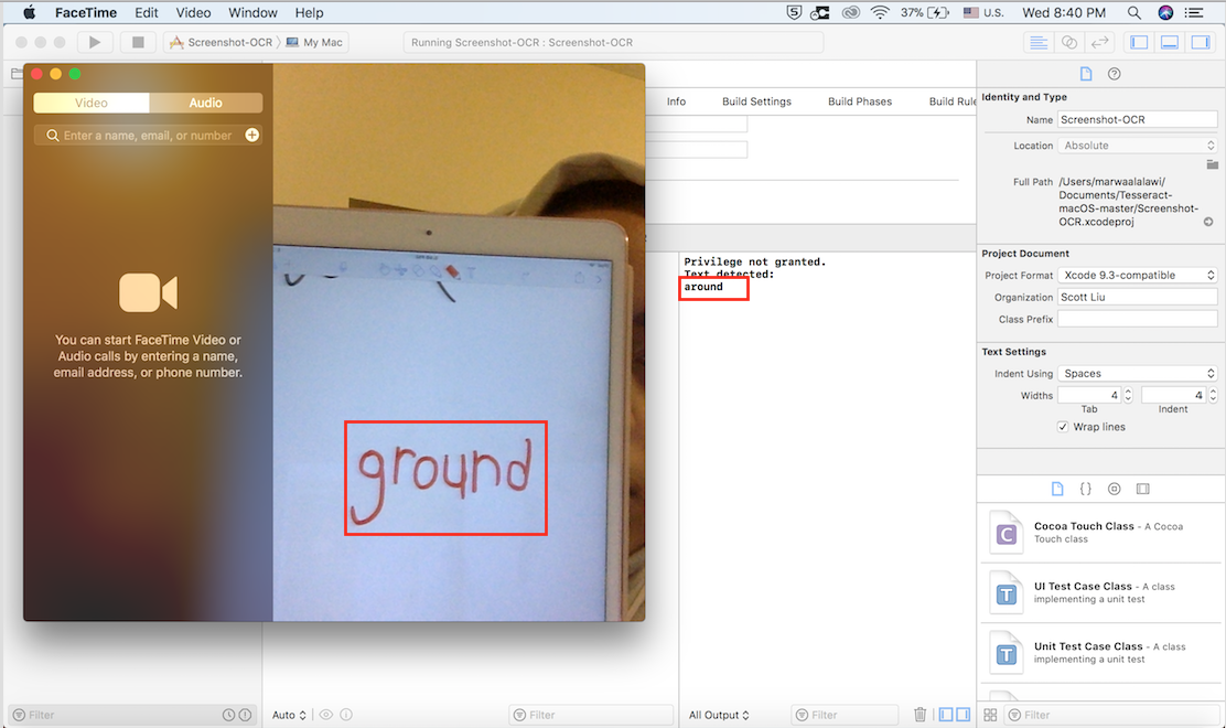
Because I will hopefully be using the pen for printed material (novels), rather than hand-written material, the inaccuracy mentioned above should not pose as a hurdle.
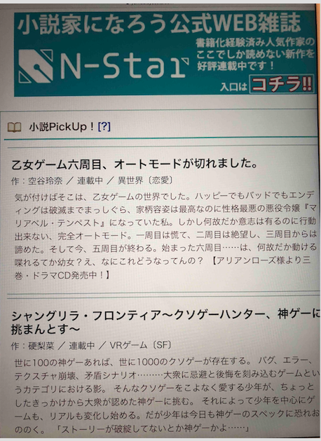
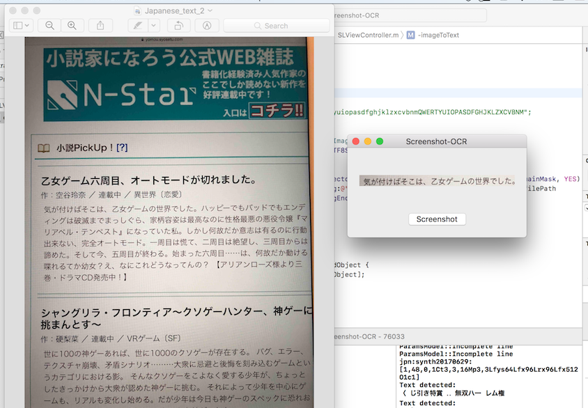
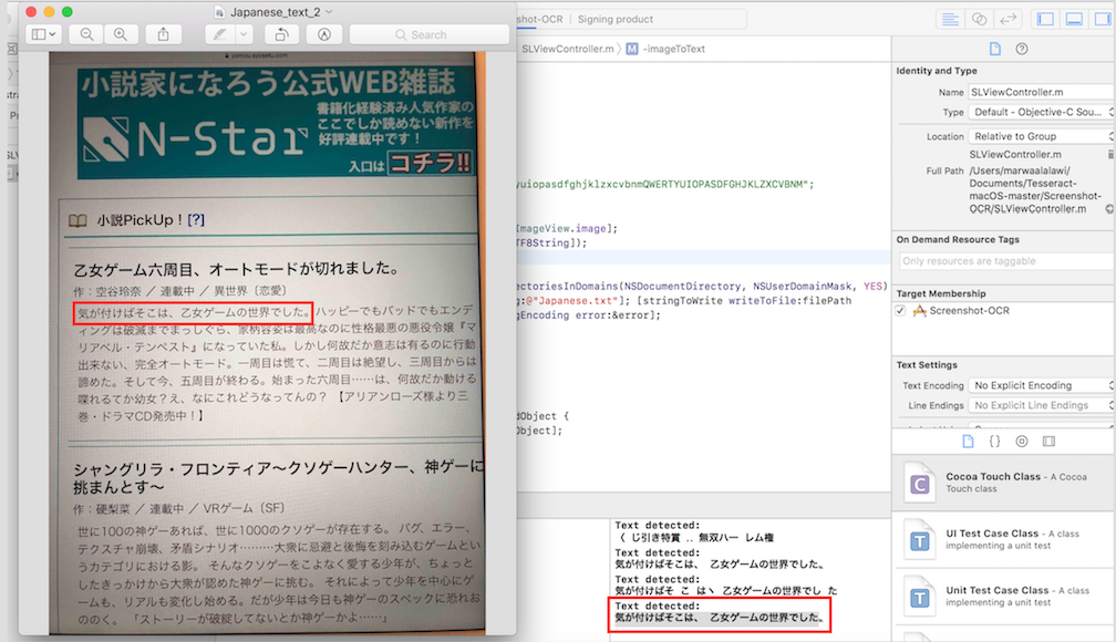
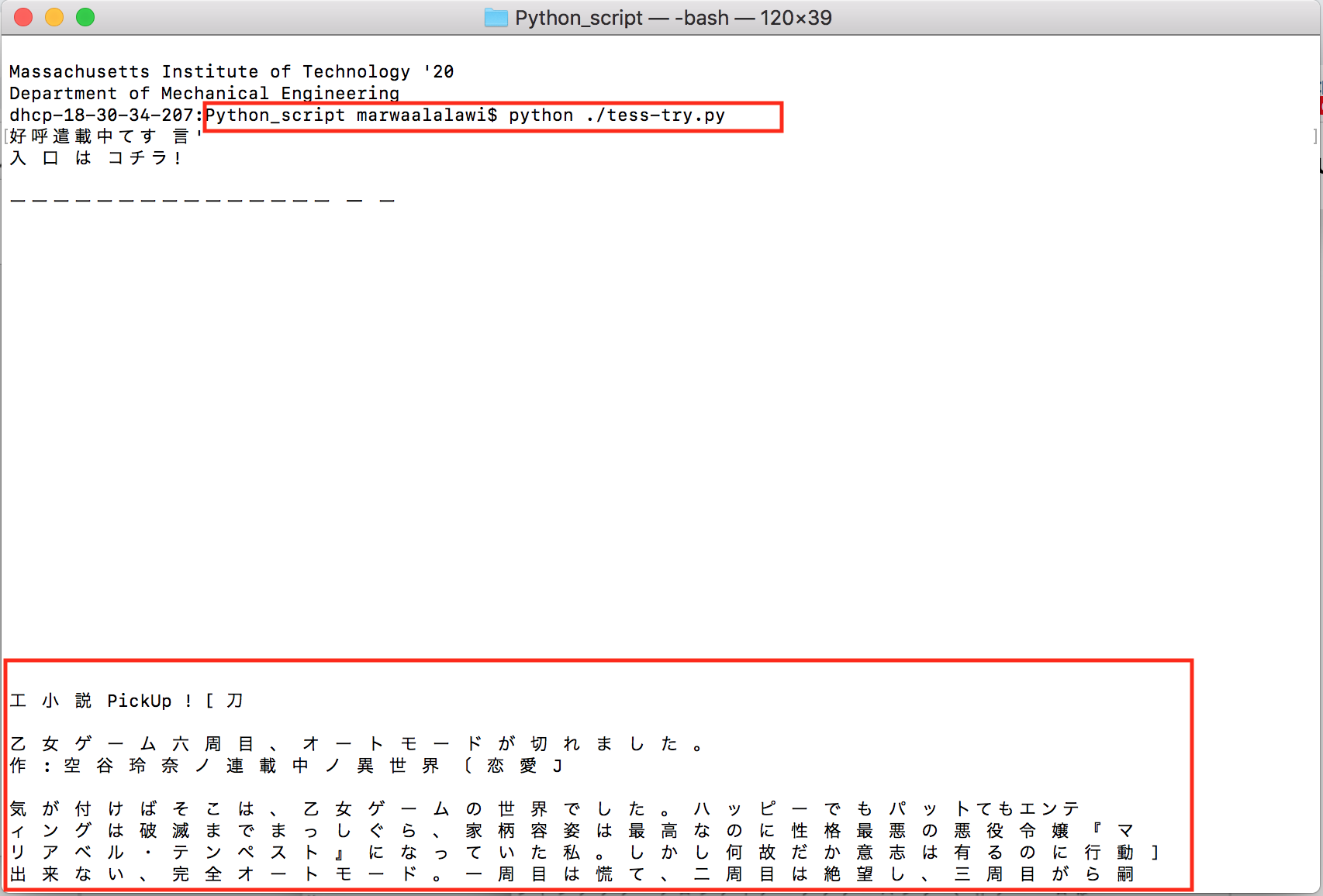
To test for Horizontal Japanese writing, I took an image with my phone of Japanese text, sent it to my laptop, then took a screenshot of it through the tesseract example code I changed from the deafult English text detection to Japanese detection. Note that to do that, you would have to go the file SLViewController.m and within the function ImageToText change the ocr.language from "@eng" to "@jap" for horizontal Japanese text.
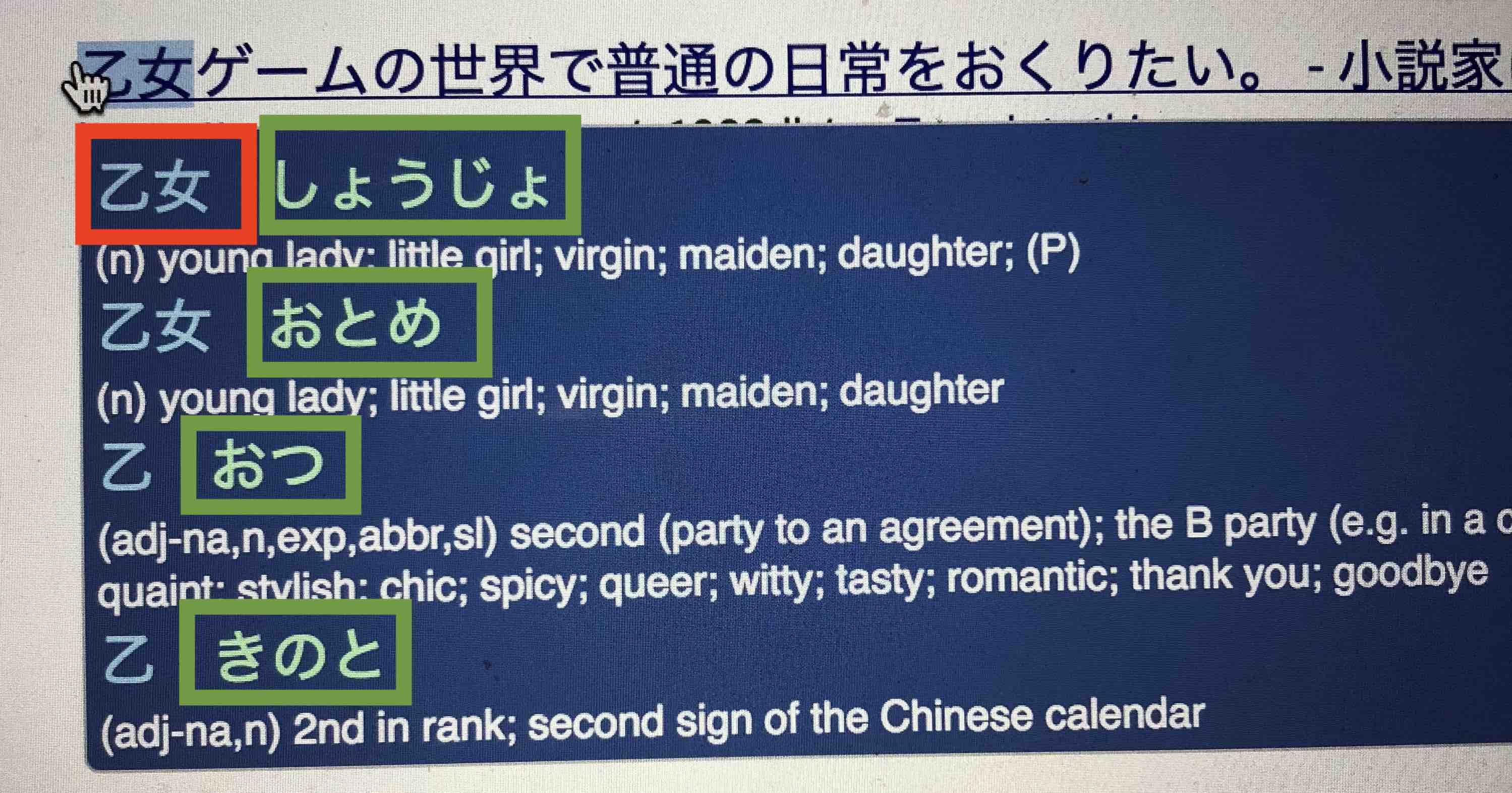
As I have mentioned in the previous (very long ago) section of this page, Google has a wonderful extension that basically produces the output that I would like my scanning pen to do (only limitation is that it does it for pure text, and not for images). That is, provide the reading of the Chinese (Kanji) chracters in the form of native Japanese characters (Hiragana). This google extension is called Rikai-kun. The picture below illustrates what I mean. Highlighted text (as wel as one bordered in red) is written in Kanji. Text in blue bubble and bordered in green is the Hiragana reading of the Kanji.
Rikaikun Google Extension: After some searching online, I found that Rikaikun is actually based on a free open source Japanese Dictionary called JMdict/EDICT
Setup:
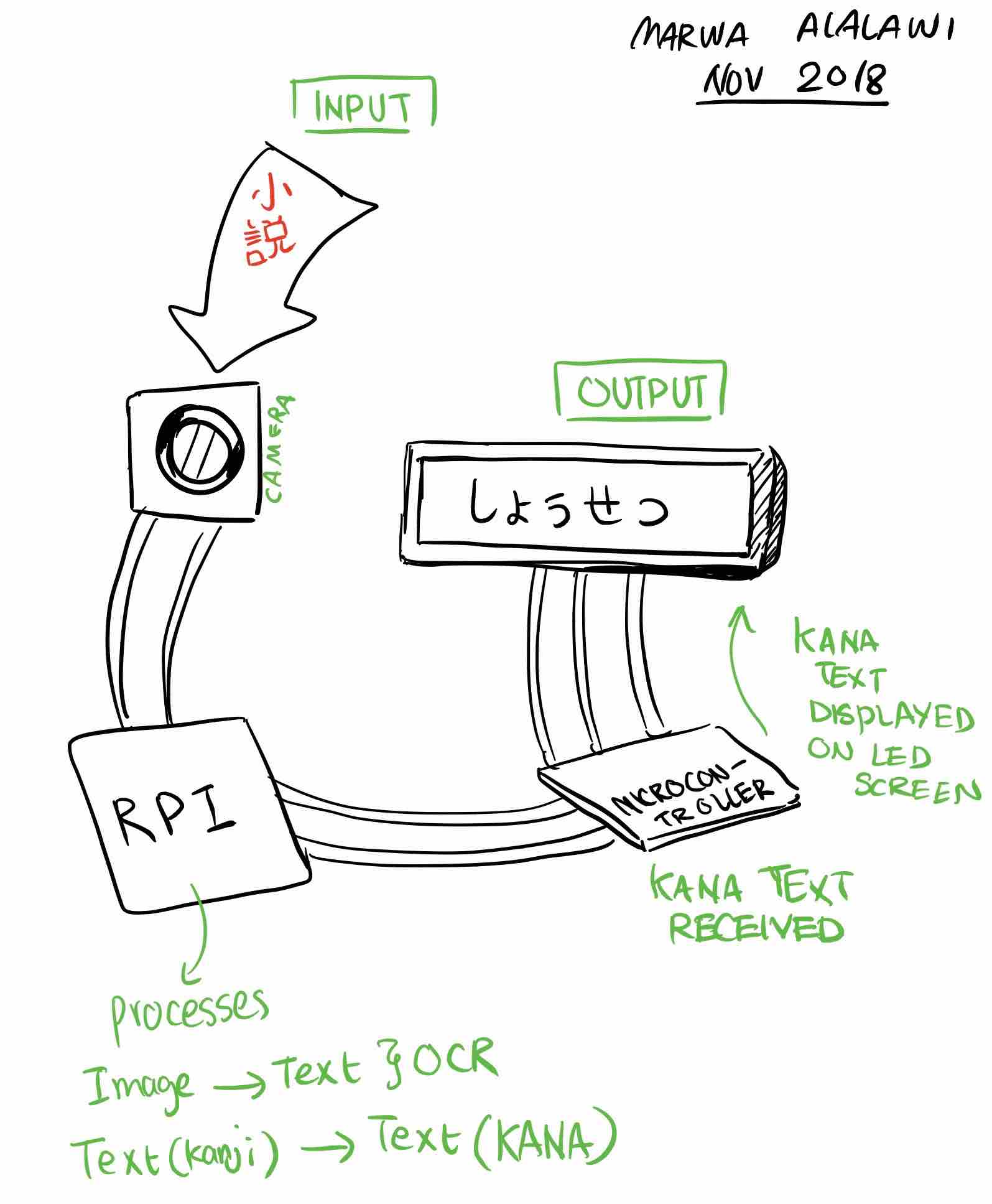
I am thinking of using a RPI zero, a microcontrorller that I build by myself, a camera, and an LED screen. The LED screen would connect to the microcontroller, and the microcontroller would talk to the RPI. The database would be in the RPI. My idea is that when a picture is taken, it is sent to the RPI, which in turn uses OCR to produce text and translate it. It then would communicate with the microcontroller and send it this text, which the microcontroller would then display through the LED screen. I am thinking of something along the lines of this tutorial, except that I don't plan on building a C# interface with visual studio.
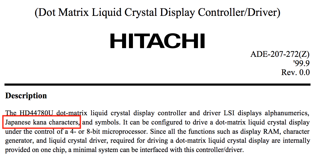
On the fab website, the suggested LCD is a Hitachi, and supports KANA characters, which is good for the purposes of this project.
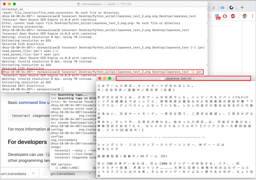
To run Tesseract through the Command line in Terminal. Basically use the following commands. (This is assuming that Tesseract is installed). Note that the default detected language is English. Also note that the deafult output for Tesseract, if directory is not specified, is the deafult home [Can be acessed on a mac if you click on Finder==> Go==> Home].
Note that the deafult format for output with tesseract is "txt". Also note that if your directiories or file names have "spaces" between them, use "" to encapsulate them.
Python & Tesseract: I researched which coding platform would work best with RPI and Tesseract for OCR purposes, and found a good number of tutorials/pages on how to combine these three elements together. To use Python with Tesseract, we first must install a couple of dependencies. Run the following code in your terminal window:
If you do not have a python installed, and are using a mac, then run the command "brew install python". That is also assuming that you have homebrew installed, which if you don't==> run the command (/usr/bin/ruby -e "$(curl -fsSL https://raw.githubusercontent.com/Homebrew/install/master/install)")
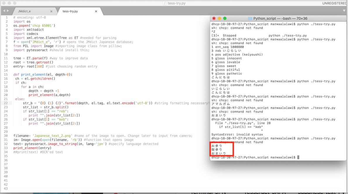
I created a simple python code as a draft. The python code currently works for English, but pytesseract hasn't been set for Japanese yet, which is why if I insert an image in Japanese text to it, I will receive an error message. If you want to create a python file from terminal==> "touch file_name.py". This creates a file for you on your user Desktop
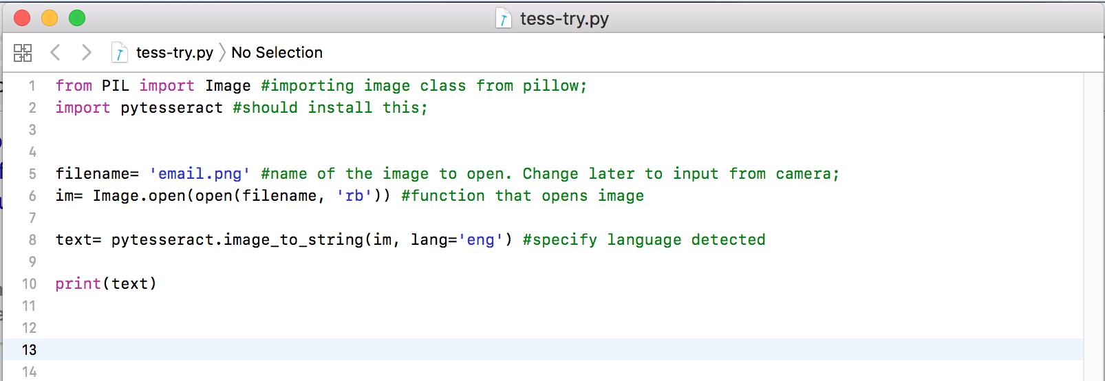
To run python code from command line==> python ./code_name.py
TOUBLESHOOTING AND BUGS: So, To actually install tesseract and have the languages all installed through terminal correctly, I did the following. I Install Tesseract like what I outlined earlier, and then typed the following in terminal:
This allowed me to see where tessdata directory is located; For me, it happened that my tessdata is located in the following directory==> cd /usr/local/Cellar/tesseract/4.0.0/share/tessdata/
Mapping Kanji Text to Database: I downloaded JMDICT, and will use it as my database since it includes KANJI mapped to KANA. I looked at this tutorial to help me set off.
Parsing: The JMDICT database is structured in a way such that each entry contains a structure of elements, which means that if we would want to access the entries and the elements within them, we would have to "parse" data according to this page.
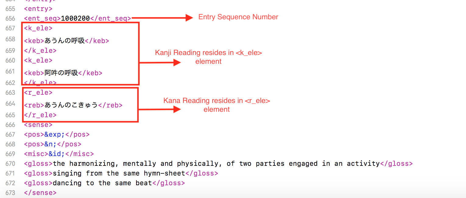
As a prototype for the code/database combination, I wrote a code where I would randomly select a Japanese entry in the database, and only have the Kanji and Kana readings be printed. I ran into some difficulty breaking up the strings (since xml is just wierd), so my friends Sarbari and Haripriya (course 6) helped explain, and guide me through. Notice how in the picture the Kanji and kana are both printed.
Final Code: I was able to successfully extract the kanji and kana elements using beatiful soup. The following code was only run once so that it creates the new database for me. The next step is to use this database and make it an even more useful format using Pandas.
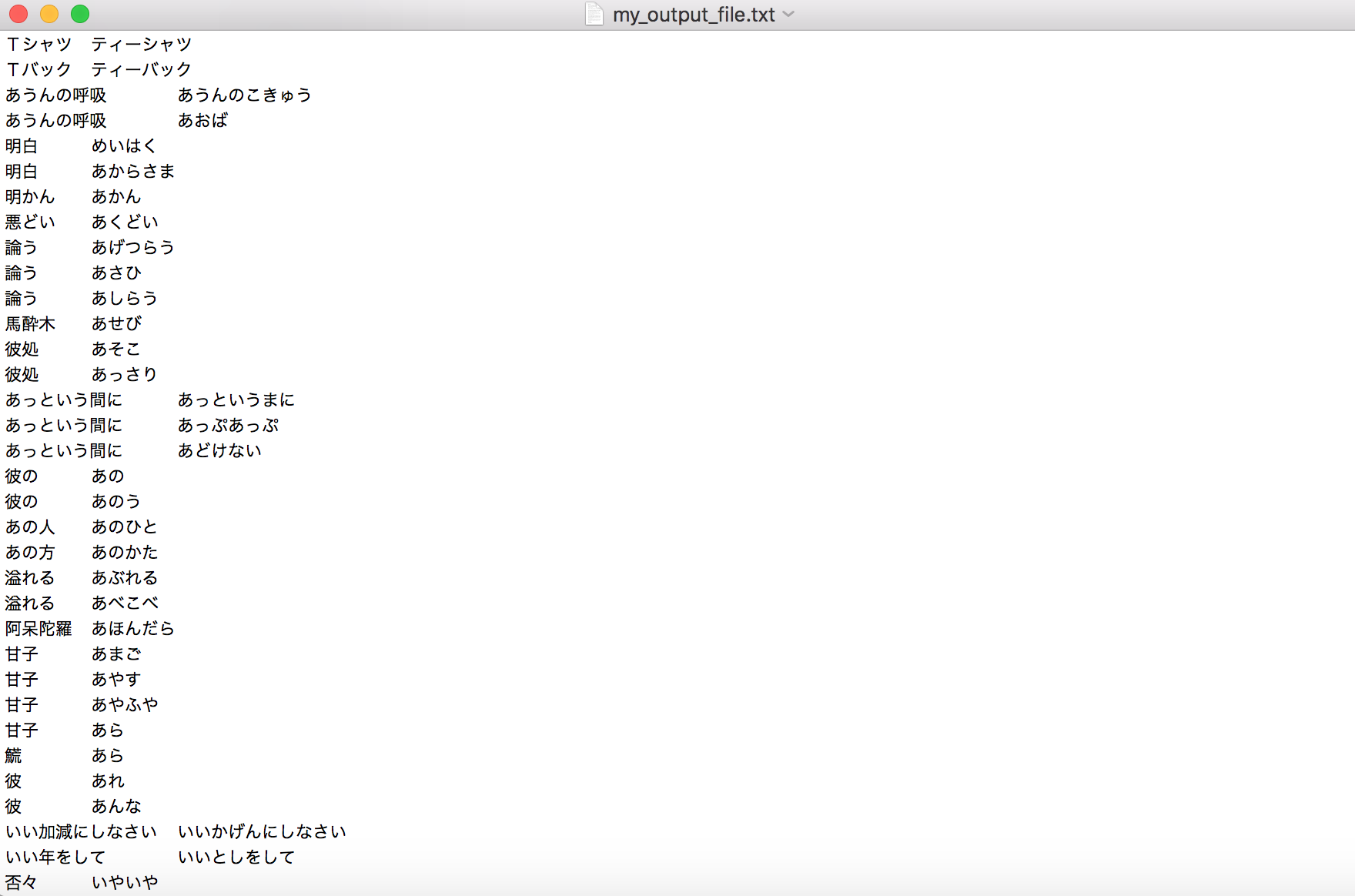
Creating Database columns with Pandas: My freind, Haripriya, recommended that I use Pandas for database easy access reasons. I currently congergated my data into a python dictionary, and have this iteration of code running for it to return the Kana reading from a kanji detected by Tesseract.

Communicaton Between RPI and AVR ATTINY44 The idea is to have a button that controls the camera, and an LCD attached to the AVR ATTINY44 microcontroller I'll make. The camera is connected to RPI. However, for the camera to turn on, and for text to be displayed, communication is required between the two. I looked at this tutorial to know how to start about.
RPI zero and Camera
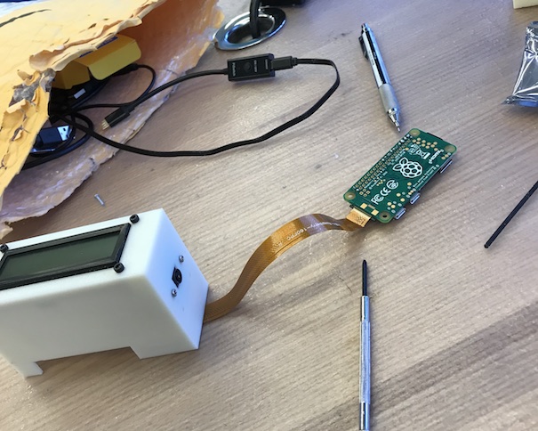
By using the camera documentation for the raspberry pi, I put together a code that allows the camera to activate or preview, and takes a picture to be saved on the desktop of the pi. Process was pretty straight forward except that I ran into two problems: first thing is that if you are using a pi zero, it will require a separate camera to pi adaptor. And second, the camera might be out of focus, so to focus it you can use a pair of tweezers to rotate the camera rim.
I was able to successfully connect the raspberry pi camera module to the pi and actually put together a code that would take a picture and save it to desktop. The code is as below: (Note that this code is run on python on the rpi)
Tesseract and Pi Camera
The next step is to have tesseract installed on the pi, the same way it was installed on my laptop (including languages data files). I also had to install pyresseract, which I did by simply running the Linux commands for installing that, but before that I had to install some dependencies like python setup tools and the library for jpeg that pillow uses, as well as pillow. I also had to use the command sudo and “no cache dir” because the pi would complain about memory errors!
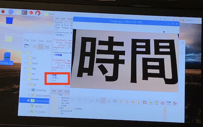
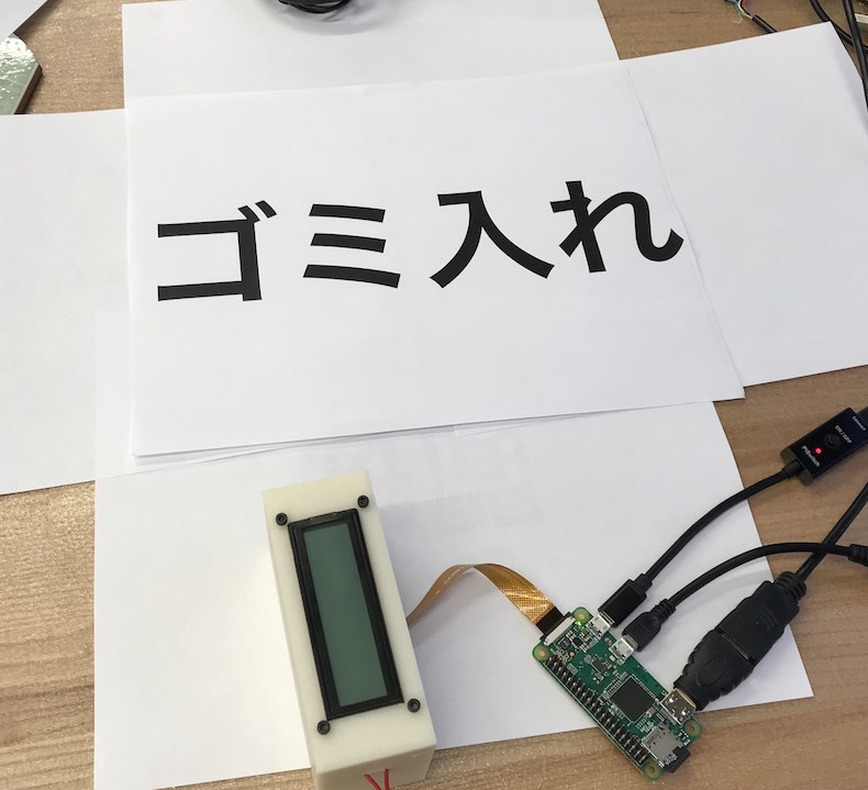
I was then ready to test tesseract with the pi camera. I simply used my code from earlier but instead of a screenshot image, I used the image taken by the pi camera.
For the best conditions for having a picture processed correctly by tesseract, the image dpi must be 300, and the text should be against a white background without any noise (even the slightest noise may skew results).
Switching LCD Modules
As you might recall from Output Device week, I ran into so much trouble with establishing serial communication with the LCD that was given to me in lab and debugged a lot with Ben but we couldn't figure out what was going on. So, Ben suggested I buy a new LCD model and establish an I2C communication with it. The Schematic for this board is uploaded on Networking Week. The only thing that should be omitted though is the presence of the voltage regulator which was unnecessary to begin with in this case. The voltage regulator precluded the LED from receiving the 3.3 V it needed and wa thus removed.
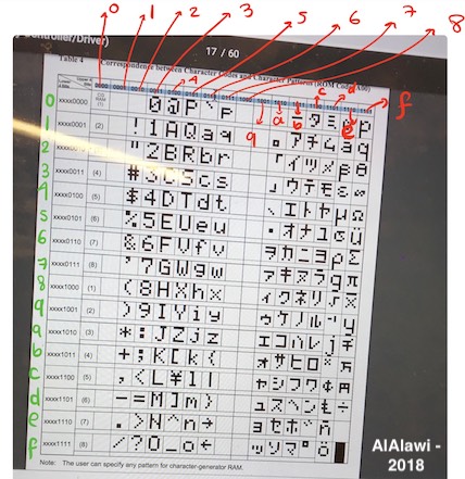
One thing that had to change in my database by using this LCD module was that this module only supports Katakana, and NOT Hiragana. In addition, it understands Katakana when it is in a binary sort of mode. So, I had to change my database such that it maps each kanji entry to this binary mode. For example, 時間 would be \xbc\xde\xb6\xdd. You can see a conversion chart below that I put together. Thanks to Ben for pointing this out to me this conversion when plain Katakana was not printing and I was confused. Also below is an example code of how to communicate through I2C with the LCD module using Arduino. Note that if you are using an attiny, you would have to include a software serial library and declare your serial as a variable and assign the pins corresponding to RX and TX to it, which is (0,1). This is not necessary to do if you use an Atmega, as you can call Serial normally (Atmega is actually very similar to an Arduino). Another important point to mention is that for I2C communication between the LCD and the avr module of choice, you either use a TinyWireM library for attiny, or a Wire library for Arduino or Atmega.
Switching from ATTINY to ATMEGA
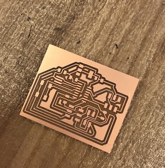
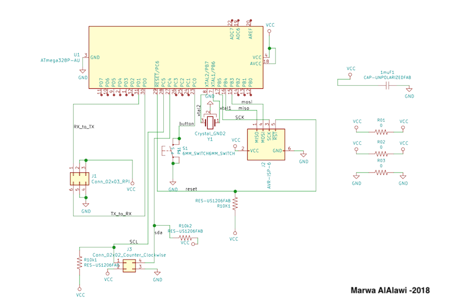
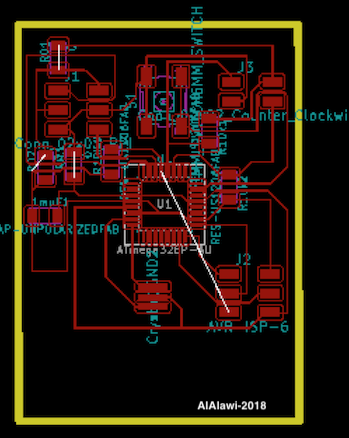
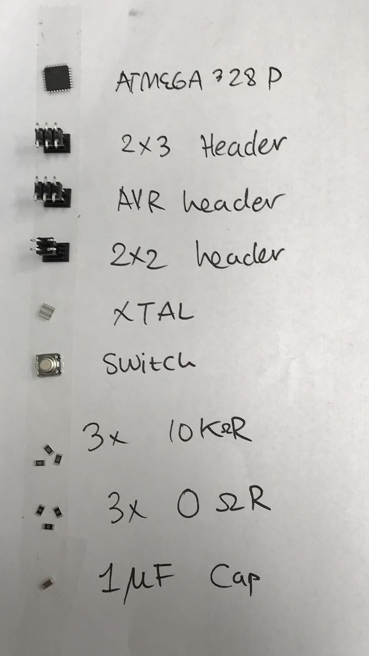
I ran into some problems with reagrds to memory with the attiny. First of all, the tiny requires at least two libraries to carry out the function that I would like it to do. First, it has to have the software library and then the TinyWireM library. Having these two libraries together is imposible as the tiny would complain that there is no memory, which is why I decided to switch to an ATMEGA and remodeled my circuit (and of course milled a new board accordingly). Below, you can see the schematic, and the PCB design for the current board I use. Note that one trick I learned to use is the zero resistor trick, where if you cannot connect some traces you can try introducing a zero ohm resistor to help create a connection. Also note that the reset on the Programmer pins was later connected by wire to the reset pin on the mega.(Note that there was a PCB iteration prior to this one which only differed in dimensions. The one previewed here has a dimension that fits the design I made for my device, which I will introduce in a bit).
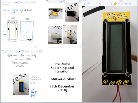
Design and Iteration
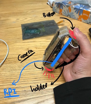
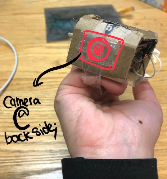
As a mechanical engineer, I am always reminded that before designing a product, a prototype using very cheap material should be first executed as a proof of concept. Following this piece of advice, I put together a cardboard iteration of what my design is. Although I wanted to make a pen like model, dimensional constraints from the LCD as well as the rpi camera size, I remodeled my design to fit all of these constraints. The images below provide a better explanation of what the design look like. Afterall, an image is worth a thousand words!
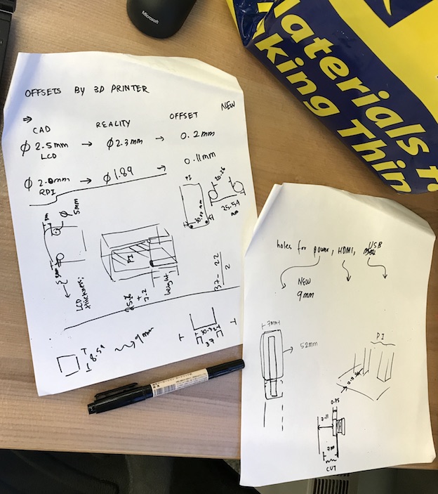
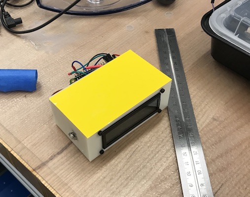
This design was translated to a first iteration of the 3D model which actually didn't match the dimensions of the design on solidworks. Apparently, the 3D printer provided additional offsets that made the design smaller than what it should be. This was especially true for the holes in my design. So, I measured these offsets and fixed the design on solidworks to match these offsets provided by the startysys.
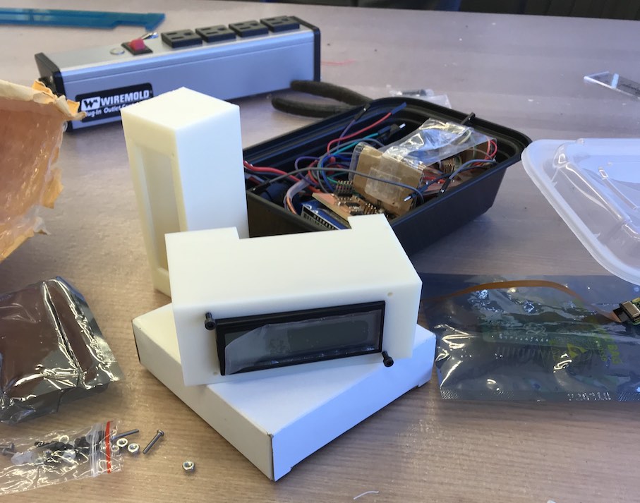
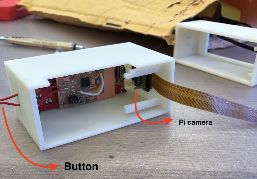
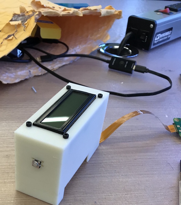
After settling on the new design, I 3D printed the piece, and started assembling the inner components that I can assemble in a way that still allows for component access in case I need to debug. The wholes for teh camera module are 2 mm, and for the LCD and button 2.5mm diameter.
Serial Communication: Pi and Atmega
In terms of serial communication, communication happens on two ways: 1) from the mega to the pi. 2) From the pi to the mega. The first portion is that when the button is pressed, a serial message in the form of a 1 byte character (here I chose the character "A") is sent from the TX line on the mega to the RX line on the pi. Once the message is received, the pi launches its camera, and takes a picture. After the picture is taken, the pi processes the picture into text through Tesseract and outputs the katakana reading. The katakana reading is then transported to the mega over serial and displayed on the LCD.
Of course before everything working out as smoothly as discussed earlier, I had to figure out some things. Like which serial port on the pi is responsible for serial communication. The first step was to diable serial on the pi config tab, and then installing picocom to see and interact with the serial port. To see the serial ports you simple use the commans ls /dev/tty since the serial ports start with tty. Apparently for the pi zero, the serial port that worked was the
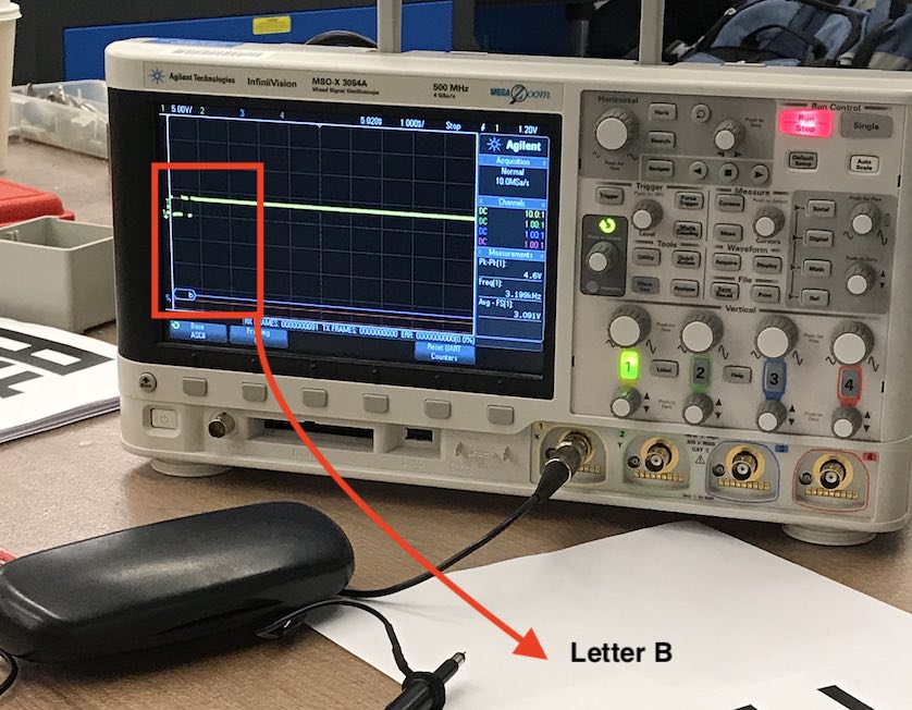
Of course before everything working out as smoothly as discussed earlier, I had to figure out some things. Like which serial port on the pi is responsible for serial communication. The first step was to diable serial on the pi config tab, and then installing picocom to see and interact with the serial port. To see the serial ports you simple use the commans ls /dev/tty since the serial ports start with tty. Apparently for the pi zero, the serial port that worked was the ttyAMA0. This was verified by an oscilloscope by opening ttyAMA0 on picocom and then pressing the letter B. The TX line on the oscilloscope showed a signal corrsponding to the letter B.
Another problem that I ran into was that my serial port was not actually working for the atmega. But a close inspection with the multimeter revealed that it was a solder joint problem (the solder wasn't actually touching the mega's pin). So, I learnt from this experience to always check my pin joints when debugging first. Check for both continuity and correctness of voltage supply. If the multimeter doesn't reveal anything wrong with connections, then use the oscilloscope to see if signals are what are supposed to be received.
A piece of advice for both the future me and current readers: NEVER CONNECT A PROGRAMMER TO A PCB WHILE IT IS CONNECTED TO A RPI. This will cause the pi to shut down and reboot by itself and may harm your electrical connections.
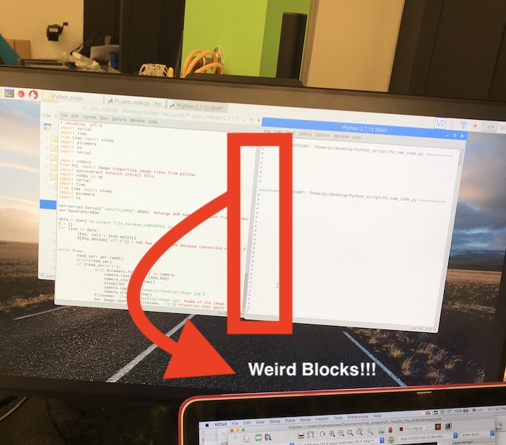
So after I verified that my TX and RX lines were working as anticipated on the scope, it was time to test everything together with the button as well. However, whenever I pressed the button, instead of an 'A' being received as a serial message, wierd blocks were printed. That was very wierd to me because the baud rate for both the mega and pi was specified to be 9600. My speculation was because it could be an ascii character, but Ben checked for me with the scope and apparently the mega was displayig a baudrate of 600! We had no idea why that was happening, so we worked around it by chnaging the baudrate of the pi to 600 rather than 9600, and that fixed this problem.
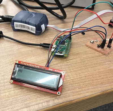
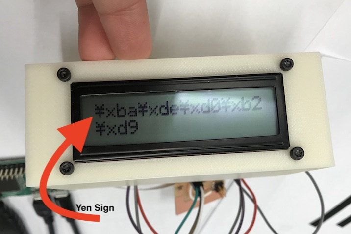
The other problem within this setion was with what the LCD was displaying ater the button is pressed and serial communicationa and OCR take place . Ironically, python was not reading the "\x" the way it should be read, and thus the result to the LCD was that the \ was displayed as a yen sign (at least, that's Japan-related).
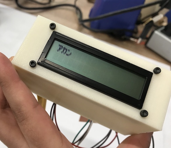
To work around this problem, Ben suggested decodeing "hex", so I basically wrote a python function that would iterate over the string and decode "hex", but it would basically only considering the elements after \x as those are the ones that python understands. The result was a success! Watch the video below to check it out! :) [Side note: I compressed the video using ffmpeg using this command line==> ffmpeg -i Desktop/kankan_1.mov -vf scale=400:-2 -vcodec libx264 -crf 20 -an Desktop/kankan_1_edited.mov
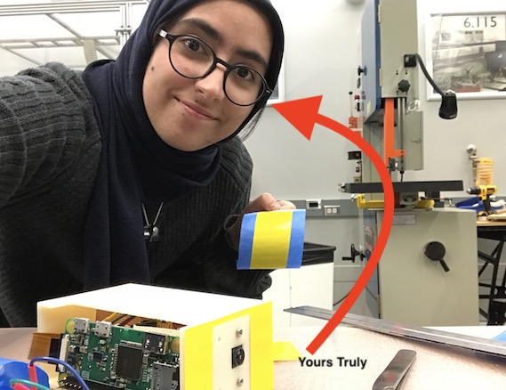
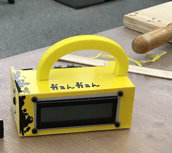
Aesthetics and Design
The first step to design and aesthetics was coming up with a catchy name and designing a mock logo for it and the overall design. I decied to call my product/device "KanKan" since it CAN convert text from Kanji to Kana.I also decided to cover my device with vinyl and vinyl design. The colors came based on what was available in the shop (in this case, yellow and black).


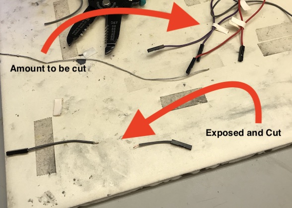
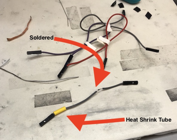
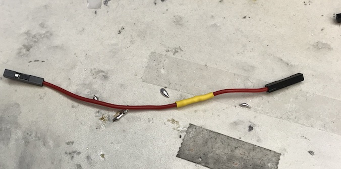
Cleaning up Wiring
Although this step was done before vinyl cutting, I just thought I would have it documented last. So, the pseudo last part was to clean up all the wiring. I simple cut the female to female wires that I had, exposed some of the metallic wire part they have, inserted a shrink tube of an appropriate size, mechanically twisted those exposed parts (for one wire of course) to establish a mecahnical connection, and soldered over it. After that I used a heat gun to shrink the wire tubes.
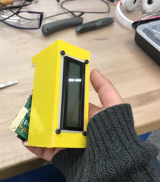
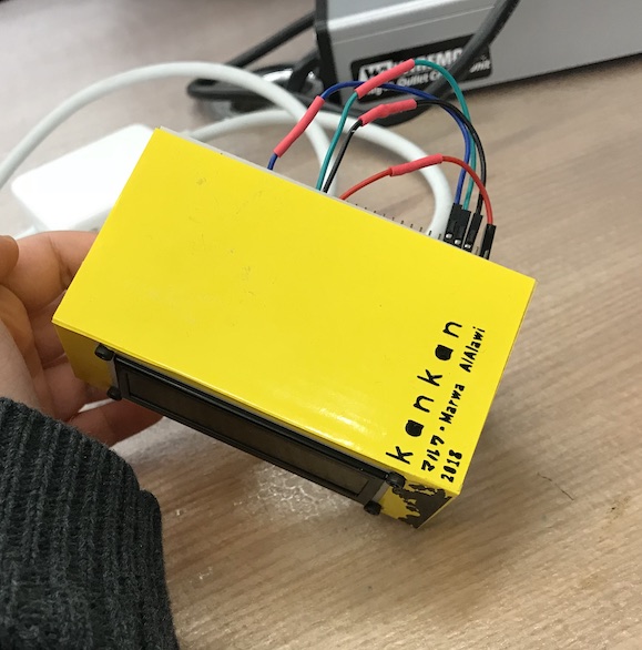
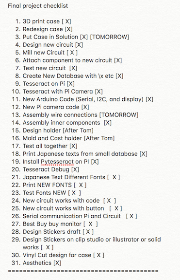
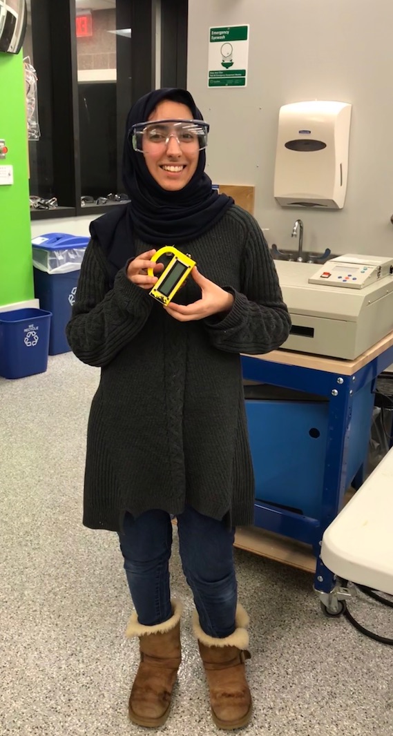
Wrapping it All Together!
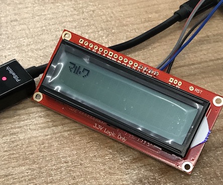
According to the list of tasks that I had to do in the 2 weeks and a half prior Final Presentation Week, I was able to meet all the things on my list (Alhamdullilah!). All that was left is to see KanKan all working together in its packaged state, and it did!!
I have also done testing with other kanji examples, and have chosen this one as another example.
Acknowledgments
"Alhamdullilah" first and foremost. Then, many many many thanks to my TA, Ben, for always being supportive and offering me sage advice. I learned a lot from him and aspire to be just like him one day. Also, many many many thanks to my instructor, Zach, for being very supportive and teaching me alot through his invaluable mentorship. I was very fortunate to have had those two as my mentors for this course. I would also like to thank my friend, Haripriya Mehta, for being a great support system and offering me advice on how to refine my data.
I would also like to thank Professor Neil Gershenfeld for making all of this happen. I learned a lot from his lectures and hopefully, one day, I can also inspire young makers the same way he has inspired me! :)

.