Electronics Production

For the longest time ever, I've always wanted to make a PCB on my own rather than have one designed and manufactured by another party
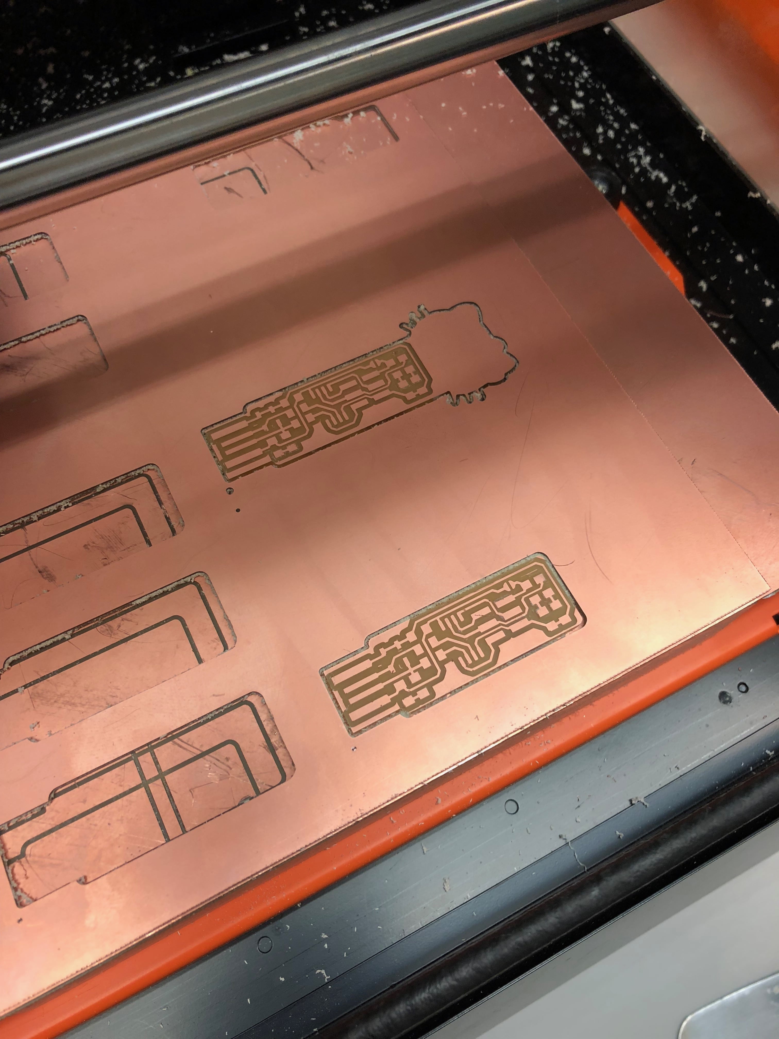
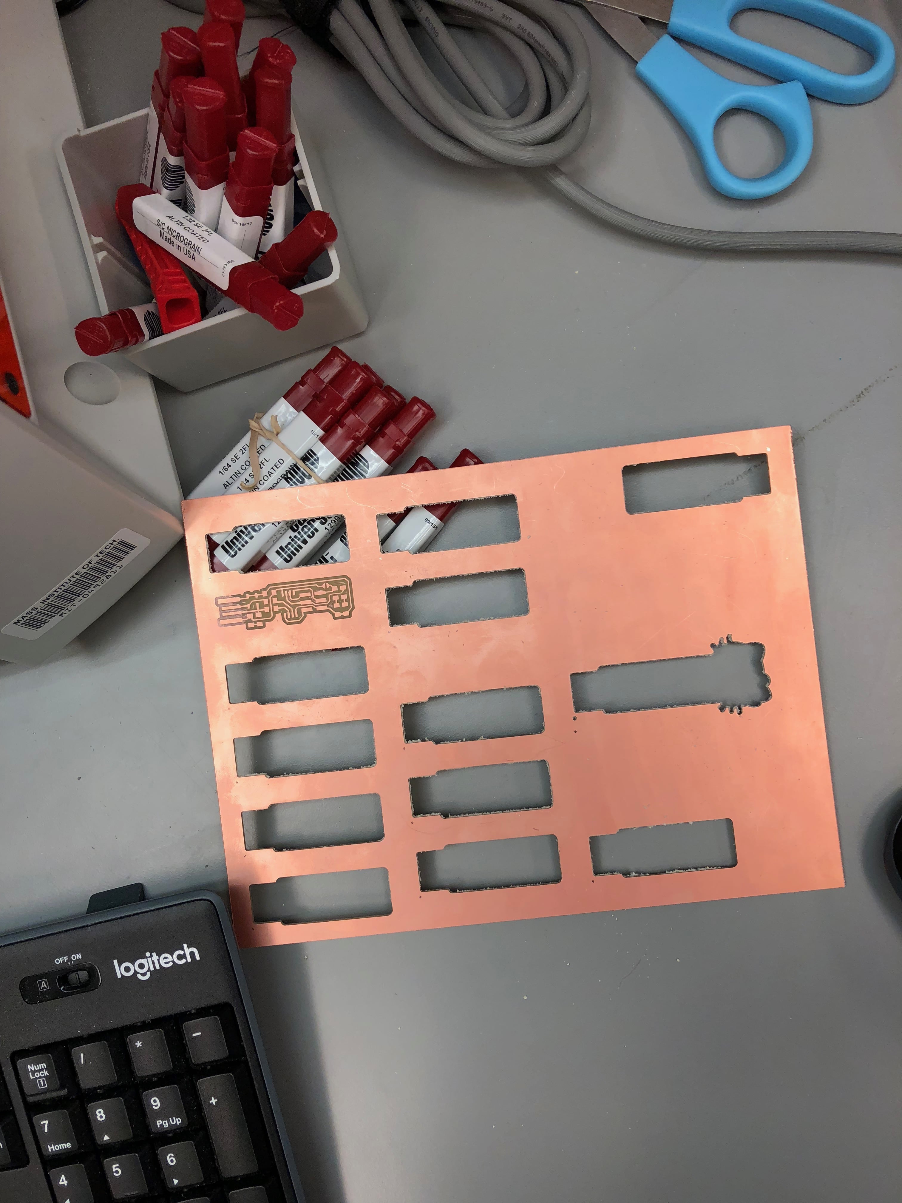
In lecture, we discussed the different ways a PCB could be manufactured, with some requiring chemical-material intervention, which could pose hazardous. One way of making a PCB is through a mill by using endmill cutting and engraving (through 1/32" for cutting and 1/64" for tracing). The task for this week was to manufacture a USB by following Brian's tutorial/page instructions.
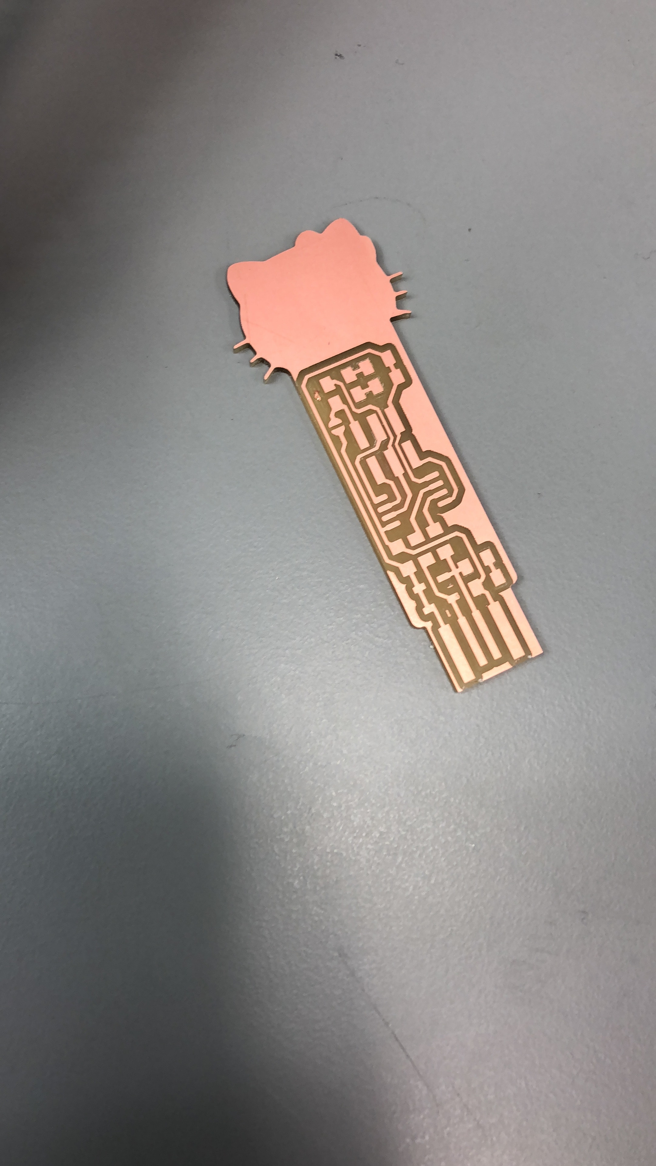
Although for this week's project, it wasn't expected of us to produce "unqiue" USB sticks, I wanted to make mine more customizable to my interest and likes (AKA, Hello Kitty).
Using Illustrator, I edited the PNG file that Brian produced for the USB's traces and border. Since the PNG file format for cutting with the mill is similar to that for the vinyl cutter, I already had a Hello Kitty design ready from Vinyl Cutting Week. So, through some edits with illustrator, I attached the "Hello Kitty Head" to the bottom part of the USB border picture, and then adjusted the traces image accordingly.
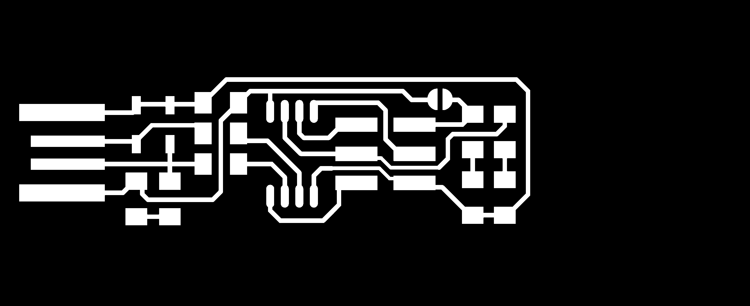
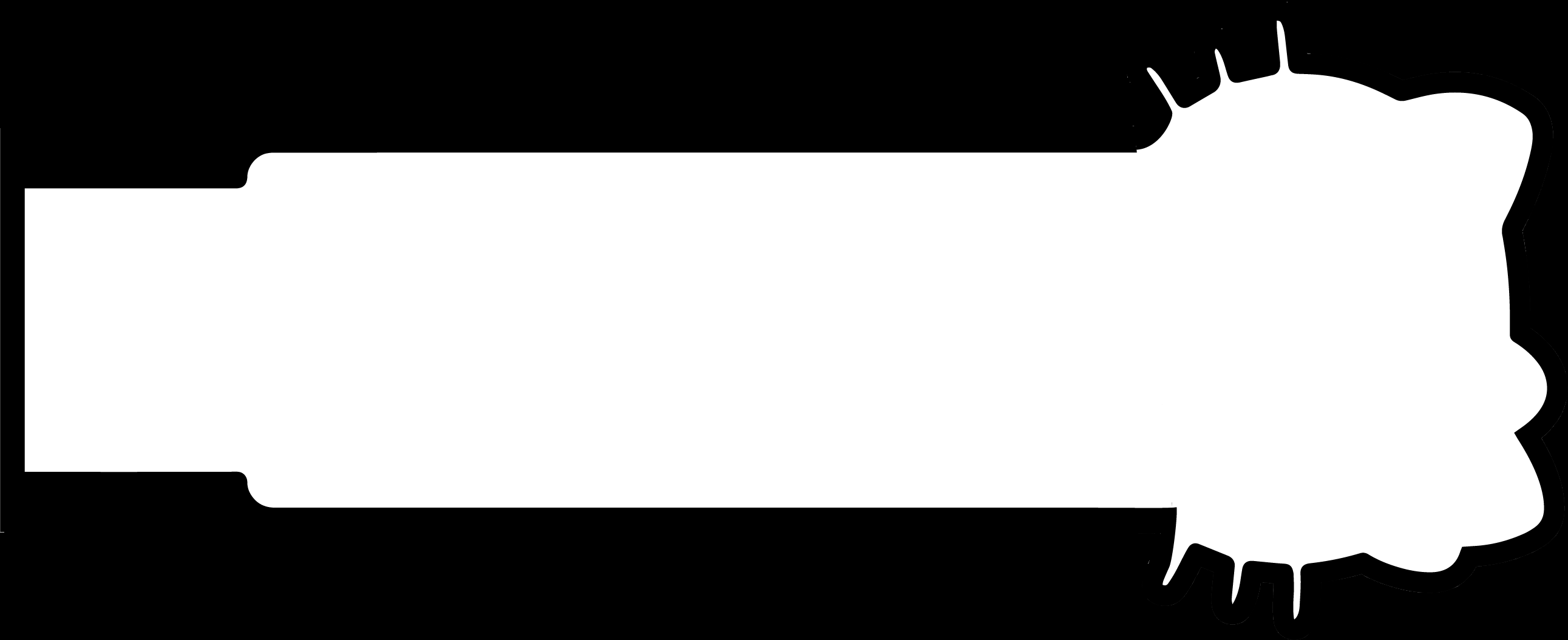
After uploading the refined designs to the MODS program, I had to make sure that all the dpis are set to 1000 before sending the job to the mill. I was a bit considered about the whisekrs being too thin for cutting, but that didn't seem to be a problem as it came out pretty well!
The second part to making the USB was to actually solder the electrical components to the board (to build the circuit board). Although I have soldered micro-controllers in the past, I never realized how DIFFICULT soldering would be, especially when the components you are dealing with are too small! Many of our teammebers, including myself, were very surprised at how small the components in PCBs are! Thanks to my TA Zach, I figured out a vital error in my soldering technique. What I used to do was hold the hot iron tip close to the solder and then let the solder drip (close, of course) on the area I would like to solder. The correct method is move the hot iron to the place you would like to solder, then bring the solder iron close to the hot iron tip, so that the solder can melt and disperse itself in that area.
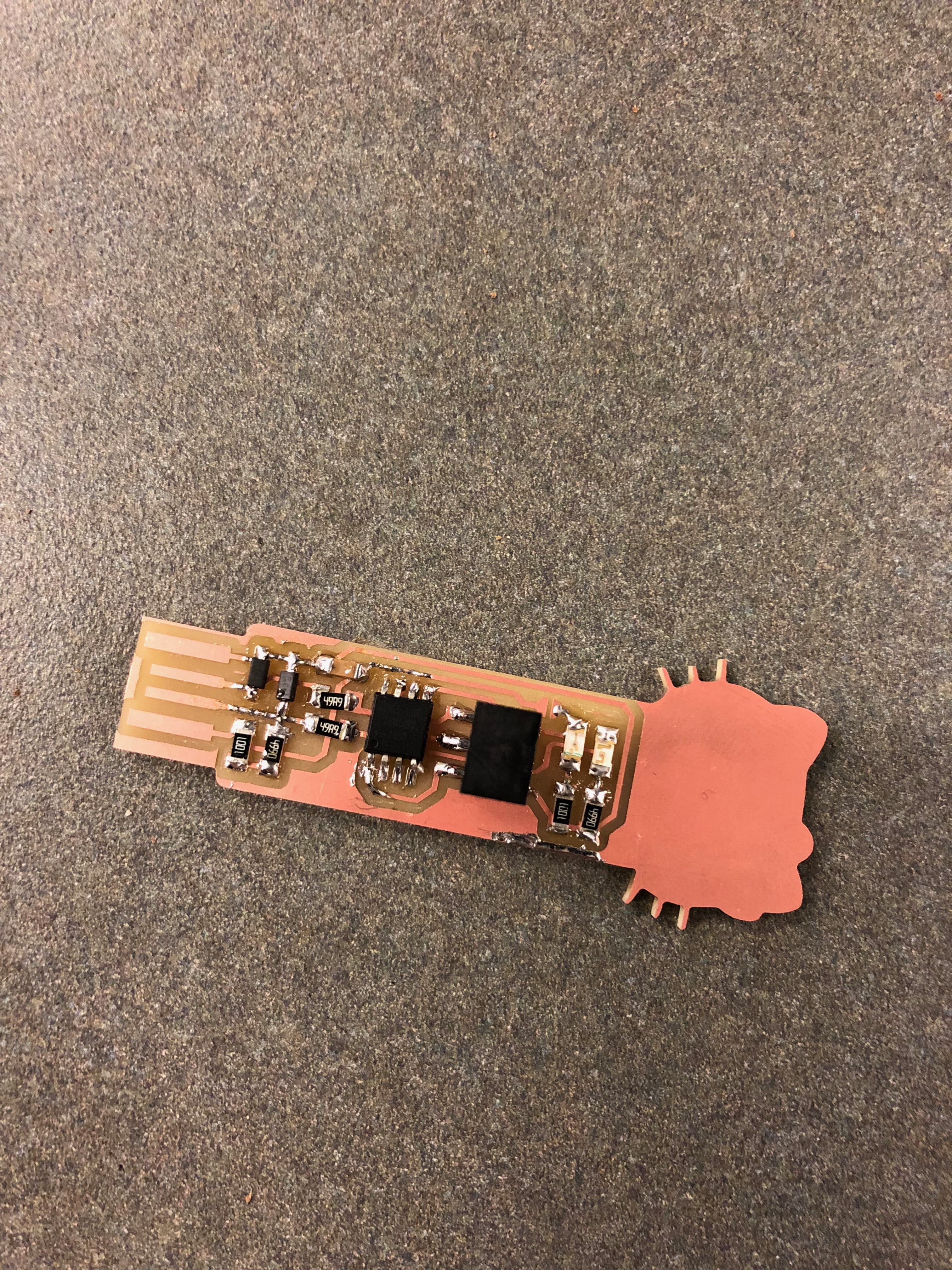
Soldering was not perfect, but it did the trick electrically! I even ran into some problems while desoldering, where I accidentally burnt out/removed part of the copper on the PCB. Thanks to Zach (again), he suggested I use a small jump wire to attach the components that were accidentally deattahed due to the removal of the copper layer. I am not sure if it is clear enough, but you can see a brown jumper wire connected to the end of the capacitor (that is, if you know which of these tiny lovely components is the capacitor :P).
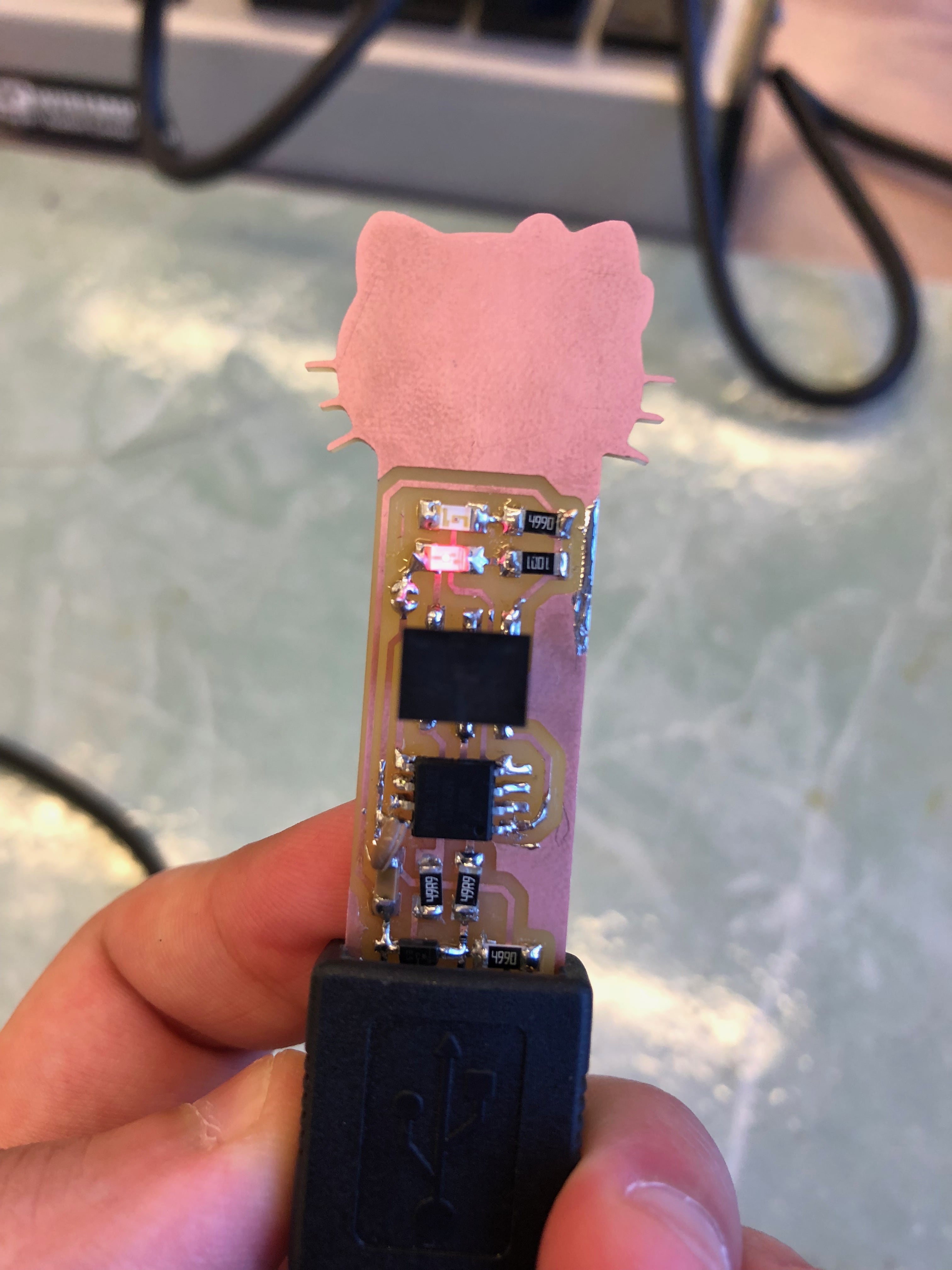
After fabrication, I had to install the software to the USB. I followed Brian's instructions, but the instructions for the Mac seemed to be a bit outdated. Although I was able to execute the "make" commands, and perform falsh, and fuse, my Mac wasn't able to recognize that a USB was inserted in it (as per the instructions). Luckily, the lab space was equipped with a Linux which Elliot--another FABlab EECS teammate-- and I used to verify that ours USBs were up and running!
Download Kitty Design Edge
Download USB Trace

.