After feeling like I finally figured out how to program microcontrollers last week, I felt ready to take on something slightly-more-challenging-than-the-bare-minimum this week. In some class at some point, I picked up the idea of a simple machine which uses very basic principles to exhibit much more complex behaviors. It's a device with two motors, which power two wheels, and two phototransistors. The idea is that you can wire the photoresistor on one side of the device to the motor on the other, and by having the motor turn either faster or slower in response to light, you create a tiny creature which will turn and drive either towards or away from shadow. It should be easy. It's the default DC motor circuit boards with a photoresistor on it.
However, in spite of having largely gotten the hang of avrdude, I absolutely have not gotten the hang of KiCad, or even basic circuit board design yet. I struggled a lot with creating a schematic which seemed to do what the default board did, and then being confused when the resulting netlist gave me results which didn't quite look right.
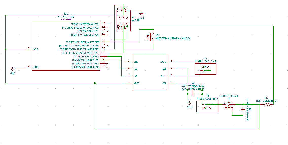
schematic attempt one

no, something is very wrong here
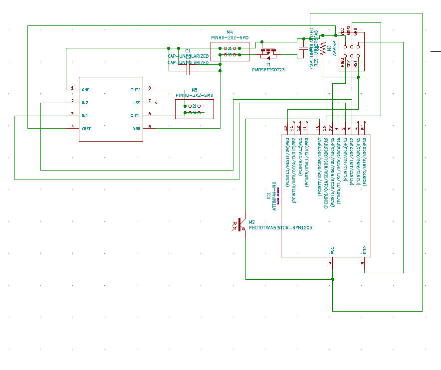
maybe starting over will help?
I eventually got frustrated, and tried to just draw the DC motor board in KiCad, and then reverse engineer the schematic. Theoretically, when the net list closed the gaps that KiCad wouldn't let me close, I would have the schematic right.

I then decided that this was rediculous, and got kind of philosphical about circuit board design generally. I head about a talk that happened last week about incorporating circuits into fiber arts and textiles, and how there's something a little weird about how we need to make circuits, which are fundamentally complex systems of connections, conform to a 2D plane, and how maybe we do this because it distances circuit design from weaving and fiber arts, because they're seen as women's work, and therefore less technical and respected. The artist's name is Ebru Kurbak.
I also just fundamentally must be mising something about how this circuit works. I decided to try prototyping by just, soldering things together with loose wires.

As it turns out, it seems like the reason why we don't really breadboard surface mount parts isn't because we're trying to be cool and hardcore and able to get things right on the first try. We do it because soldering human-finger-manipulatable-scale-wires to surface mount parts is extremely difficult.
It looks like it's time to go back to looking at schematics. Something is clearly wrong with mine, but maybe looking at other schematics from this other students for this week will help. Future HTM students-- here's a curated list of links to other people's output weeks which feature pictures of schematics which later became sucessful, dc motor-driving boards:
Things still weren't working. I finally figured out that the footprint for my attiny44 wasn't right. According to the datasheet, the pins are laid out exactly as they're labled on Neil's board, and my footprint reorganized them into some sort of default order for a microchip with 14 pins. I matched up the names, pins, and positions for each pin manually, and after, the whole schematic made sense. Future HtM folk-- don't trust your footprints!
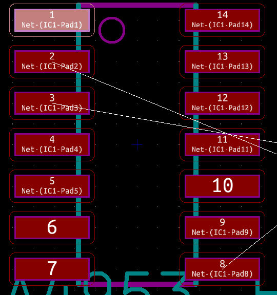
pins in default ordering

trying to be careful in figuring out what goes where

renumbered pins
I hope adding the phototransistor is as easy as I thought it was. I guess we'll find out when we run current through it.
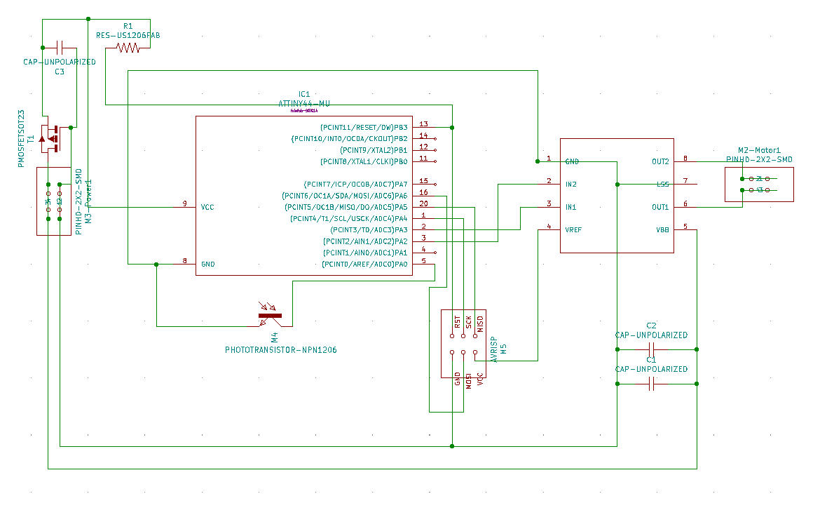
final schematic
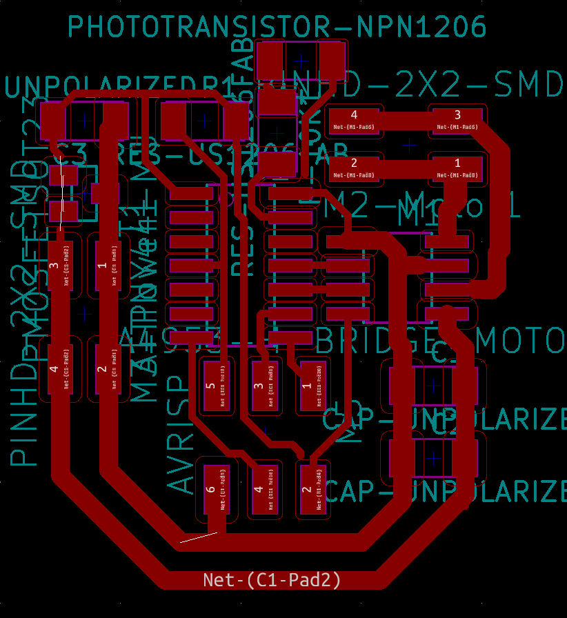
final traces
KiCad is still being a little bit weird about some of my connections, but these are just image files, and that's what GIMP is for.
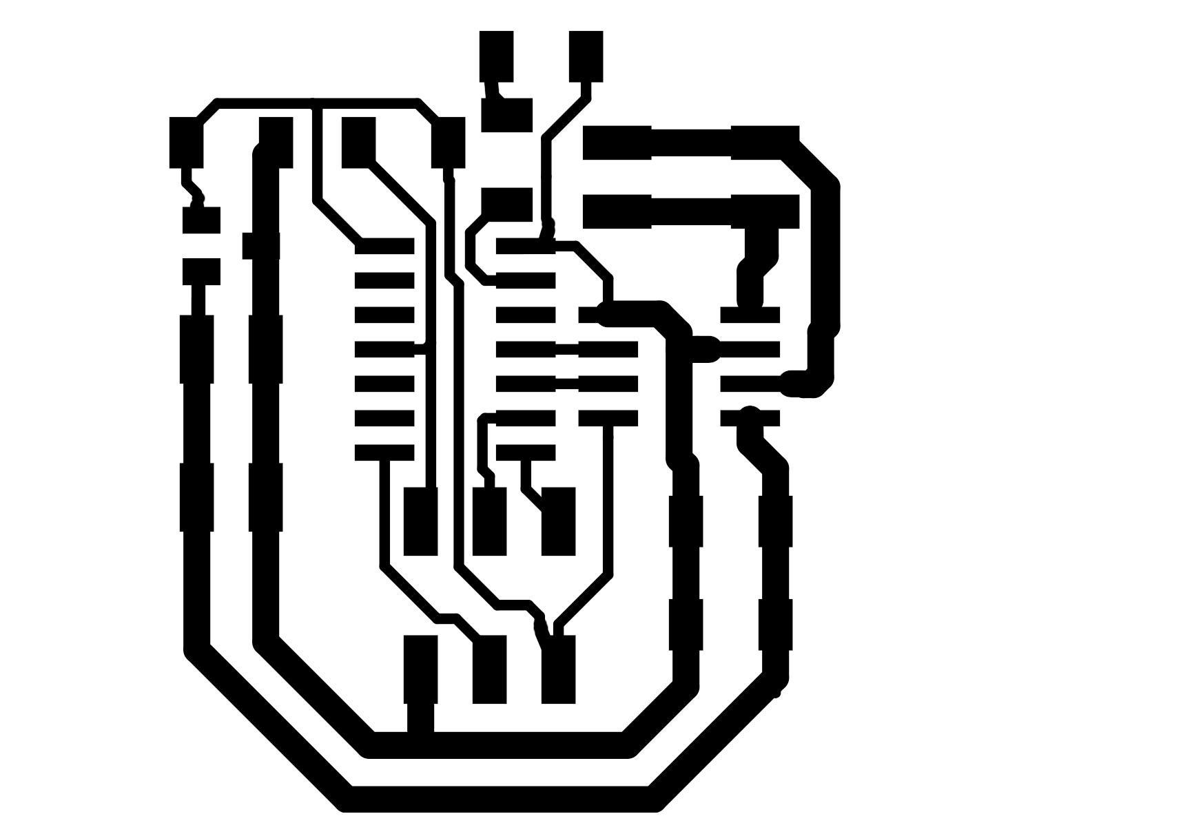
manually drawing in some of the connections KiCad wouldn't let me close for some strange reason