This page will document my final project as it progresses from initial ideas to the final implementation
As part of our week 0 assignment, we were asked to brainstorm and work on sketching ideas for a final project. Since I love sailboats, I thought that it could be really neat to make a ~1 foot model sailboat that could actually sail. Perhaps I would even be able to make a control system that could at least keep the boat sailing in a line by itself.
It actually took my pretty much all of the time I had available just to set up and figure out how to use CAD programs to make a sample hull design, and that didn't include any rigorous thought or calculation about displacement or keel depth or anything like that. For some sample images of what the resulting hull shapes looked like, head on over to my page on week 0.
I was starting to realize that this project would be really complex; I would need to calculate weight and displacement, figure out how deep and heavy the keel would need to be, design mechanical systems for sail and rudder control, and design an electronic control system that could sense heel and direction and respond with appropriate control inputs, all while being waterproof. This would definitely be a cool project, but given my other time commitments, I thought I probably wouldn't be able to complete this project in a very busy semester.
I then tried to think of something I could make that would be more feasible to make given the tools and time I have available in this class and might be more practically useful than a model boat. This led to the idea that I could make an adjustable standing desk converter, something my wife has been wanting for her workspace, but is pretty expensive to buy already-made. If I make it myself, I can also customize it with laser or vinyl-cut decoration on the top surface, built-in electronics (like maybe a timer for how long the user has had the desk in one position, or a counter to keep track of water consumption during the day), and other things related to the skills we will be learning.
My plan right now would be to design the desk so that the main structure is laser-cut plywood, with a framework that allows for easy vertical adjustment, a decorated top surface (laser-cutter burn pattern), and an integrated electronic counter/timer. I'll think of more ideas as I learn more tools, so keep checking in for updates.
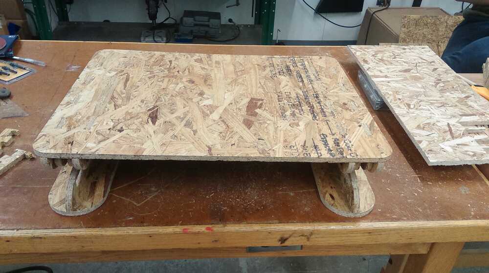
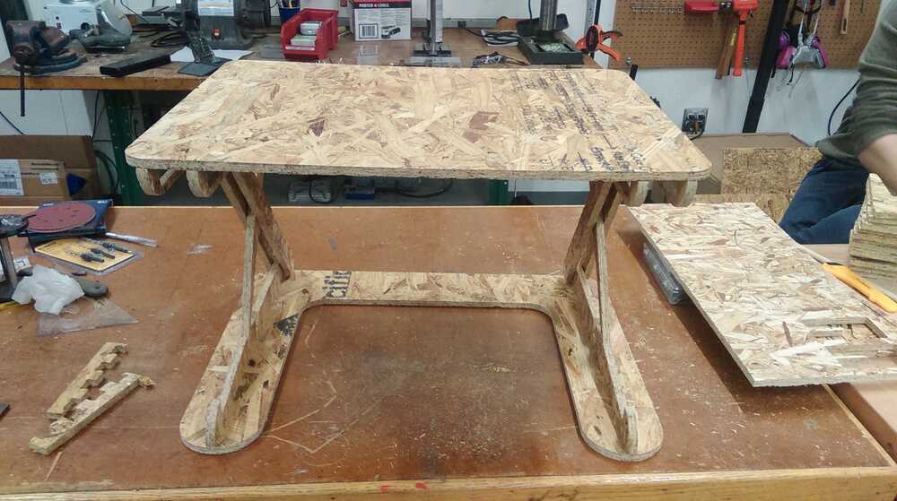
For my "make something big" week's assignment, I made a prototype of the desk structure out of Oriented Strand Board (OSB). Here's a pair of pictures of what I have in the low and high positions. There are a few problems with stability and ease of use, but I'll have a much easier time improving the design with a physical prototype to play with!
For the week on input devices, I decided to learn how to measure ambient temperature using the built-in temperature reading capabilities of the ATTiny44a. I plan to use this in my final project to allow my desk to read and display the temperature around it.
For the output devices week, I added an LCD screen to my microcontroller setup so that I would be able to put an LCD on my desk to display the temperature and other messages.
For the weeks on networking and interfacing, I added WiFi capabilities to my microcontroller setup using an ESP8266 WiFi board. This would allow my system to go online to retrieve a message to display on the LCD. This would enable me to remotely send a message to the smart desk.
As the final deadline approached, I had a prototype of the desk structure and a working electronics message and display system from my weekly assignments. The tasks remaining were to make the final desk out of nicer wood with some structural and design improvements and to package and finalize the electronics.
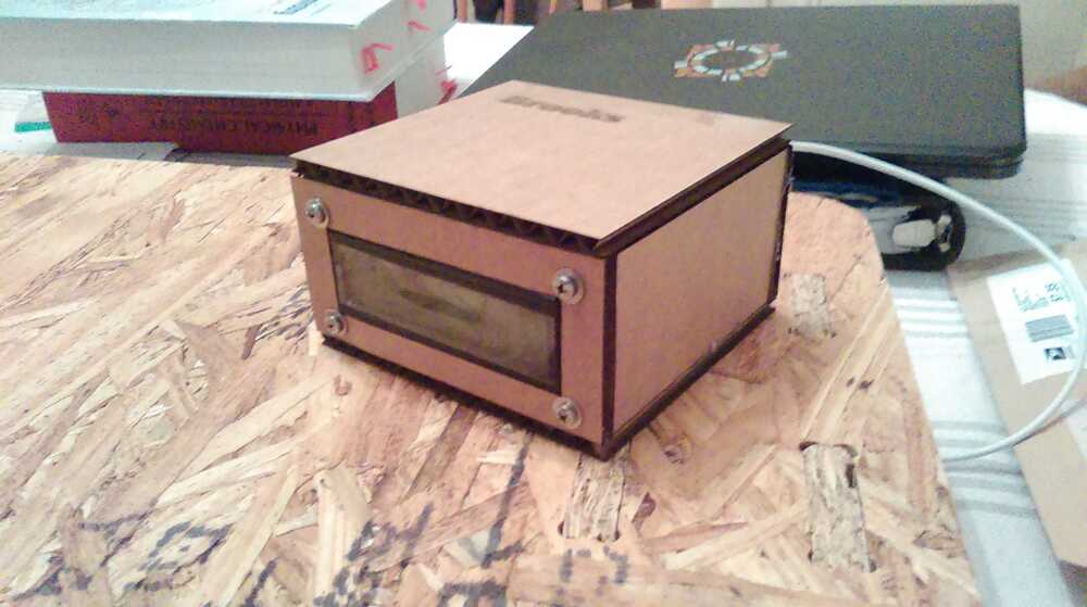
In order to make the electronics present cleanly to the user, I laser cut a small box out of cardboard with holes for the LCD screen and the necessary power connection.
I quickly designed and milled a simple board to connect a 5.5 mm DC barrel connector to an ISP header so that I could transfer power from a barrel-plug to my board, which only had the ISP header free. I then found an old 5V DC converter in the shop and soldered on a 5.5 mm barrel connector (after some difficulty working with the coaxial power cable).
I then arranged the components in the box with the cables neatly routed and hot-glued the boards onto the box for mechanical stability, leaving enough room around connectors to allow me to disconnect them to reprogram the board.
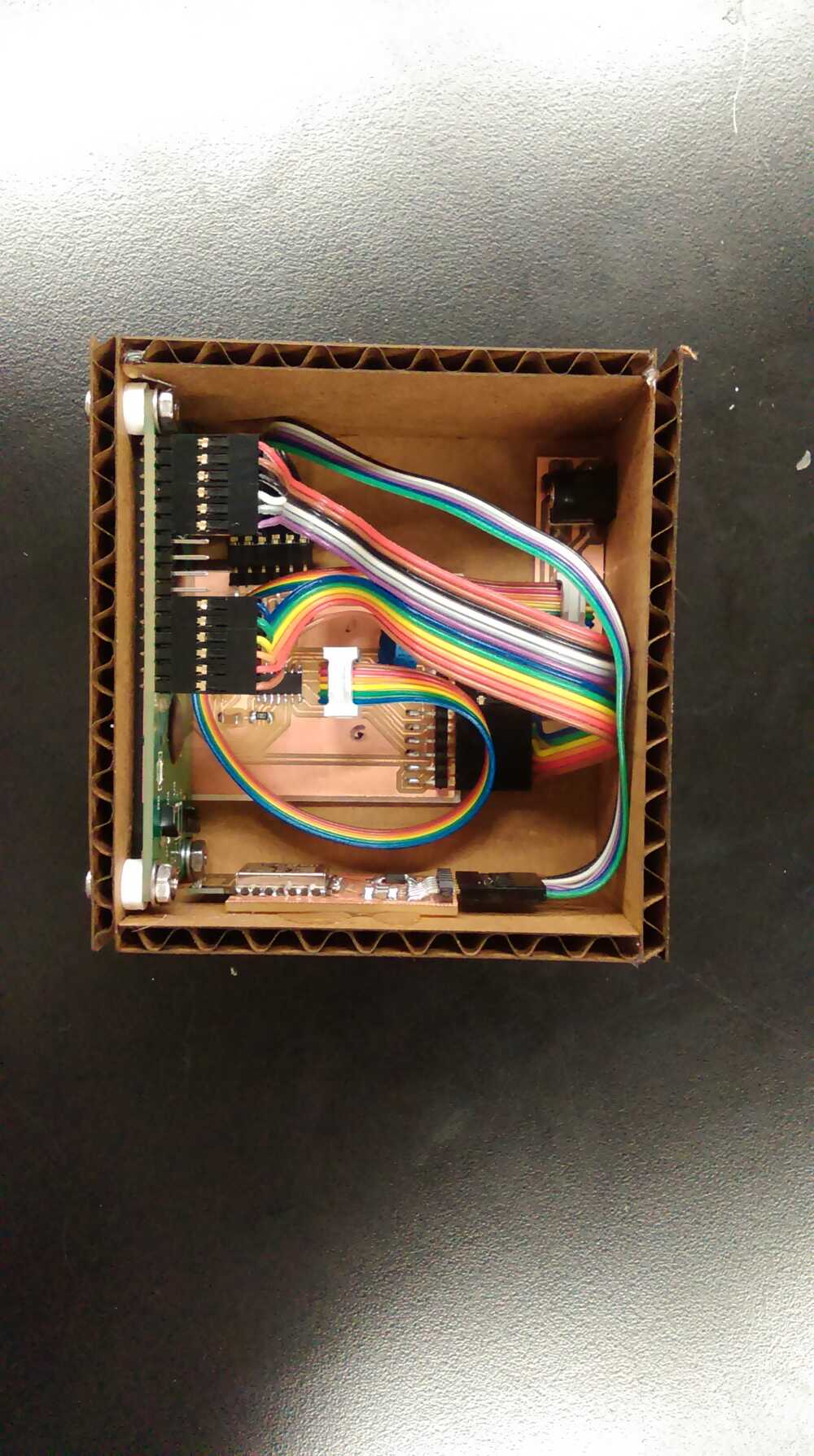
I 3D-printed some spacers to put on the screws for mounting the LCD, and a thin spacer to place beneath my main board with a hole to allow the nubs from the through-hole potentiometer to poke through. I also 3D-printed a base tray for the box to sit on. While taping the cardboard box to the desk would be somewhat irreversible (cardboard doesn't do well with tape-removal), I can tape the plastic tray to the desk and then place or remove the box as desired.
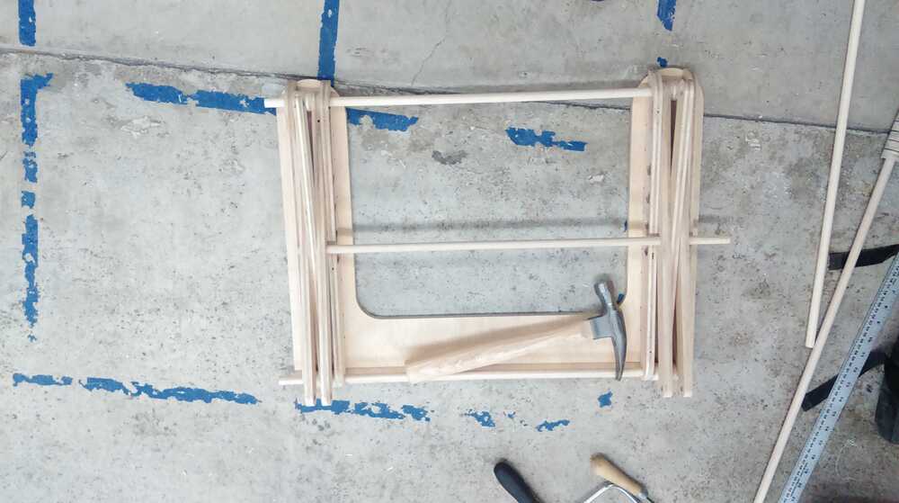
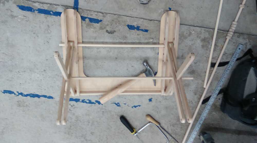
My desk prototype had some problems with stability and operation, so I revised the mechanical design of my arms and brackets. In short, I realized that I could use the design for the top brackets for the bottom brackets, preventing the sliding dowels from lifting out of their tracks or slipping to the side. I also decided to make all of my dowel-holes a bit more snug, resulting in a bit more friction but reducing the ability of the joints to wobble side-to-side. I also decided to make my dowel connectors run all the way across the desk, again to increase lateral stability, and finally, I decided to increase the size of the desk surface.
Before I started fabrication, I went to Home Depot to buy some plywood that would look (and feel) a lot nicer than OSB. I ended up getting 1/2" 'Sande' plywood in 2'x4' sheets (the biggest that would fit in my car), which is marketed as plywood for DIY furniture and other things--defect-free surface layer at a fairly low pricepoint.
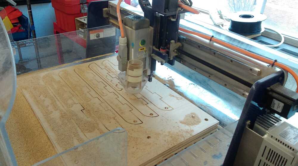
I milled out the components on the Shopbot Desktop, using the same milling parameters (0.125" flat-end 1-flute mill, 2 in/s feed, 300 rps) as for the OSB and then sanded them down to remove rough edges
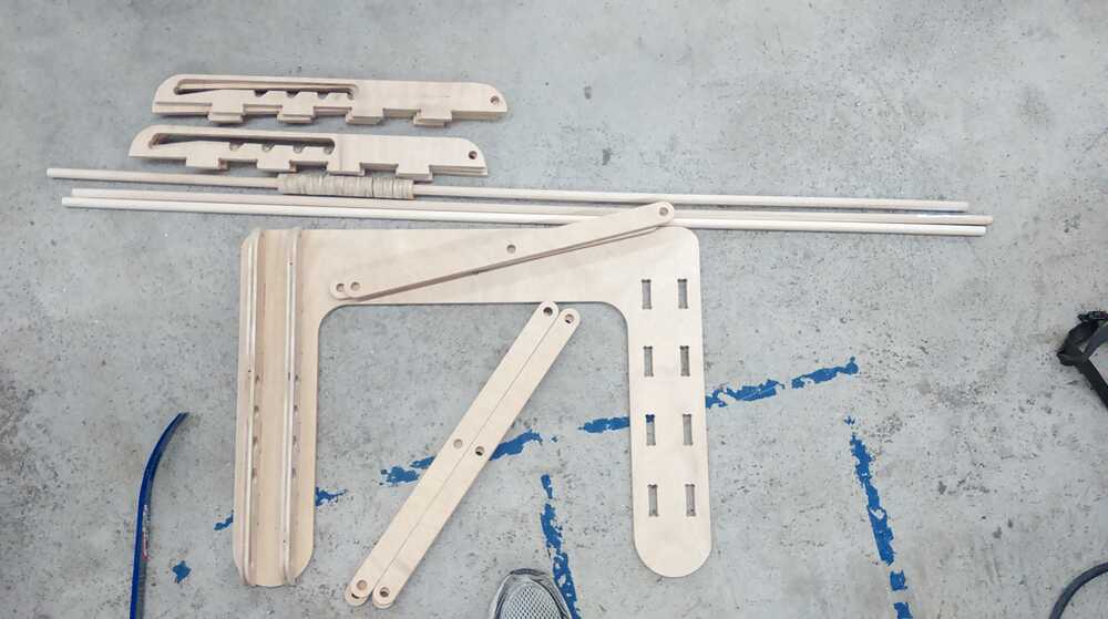
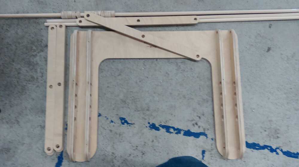
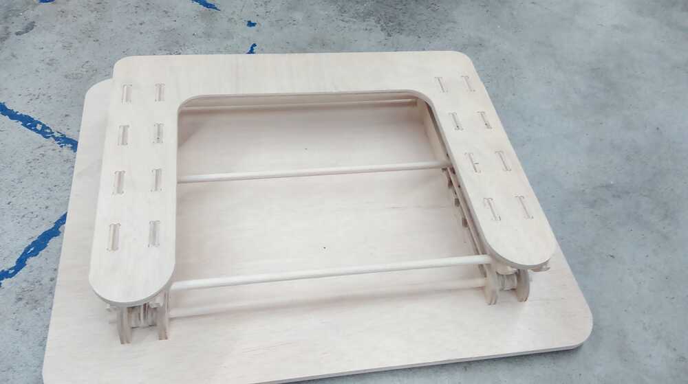
I then began assembling the parts. At this point, I realized that the plywood I was using compresses less than OSB, so the joint tolerances I had used for OSB were a bit too tight. That was better than finding they were too loose, though, as a bit of sanding and rasping fixed that problem without too much difficulty (besides some blisters). The dowels were also a tight fit, and what is more had varying diameters, so I also manually opened up some of the holes. The desk was starting to come together.
The OSB prototype's size had been limited by the size of the ShopBot Desktop work bed. I was hoping to use the larger shopbot in the Harvard physics demonstration shop to mill the desk surface for the final project, but this machine had not been working well, so I was stuck with the Desktop. After some thinking, I realized that I could still make the larger desktop if I manually rounded the corners using a scroll saw and then used the ShopBot to mill out the holes for the brackets. I used the base as a stencil to allow me to allow the larger plywood exactly on the ShopBot work table. I had to make two screw holes in the middle of the desk to fasten the piece to the work bed, but they aren't very conspicuous and add an interesting touch. I then was able to mill out the bracket holes.
I sanded the desktop with rough sandpaper as I had for the other parts, and then finished with a pass of 400, and then 600 grit to give a nice smooth finish. I then put the brackets on and finished assembly.
It turns out that my joints were a little too stiff (for the next model, I would slightly increase hole diameter and bracket spacing), so I had to pull out the sandpaper again to take out some material (standing desk or sanding desk?). After this, the desk was able to raise and lower as designed, if still a little bit stiff.
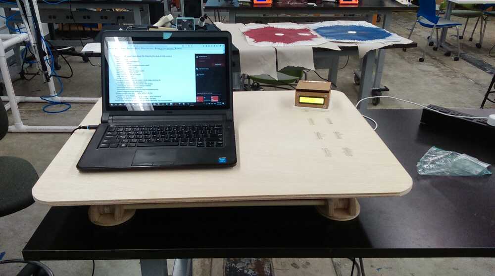
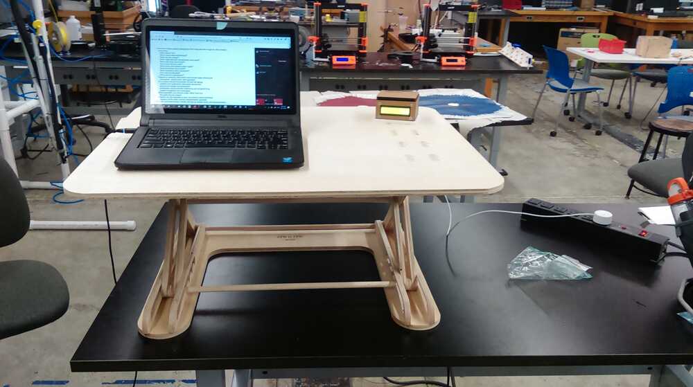
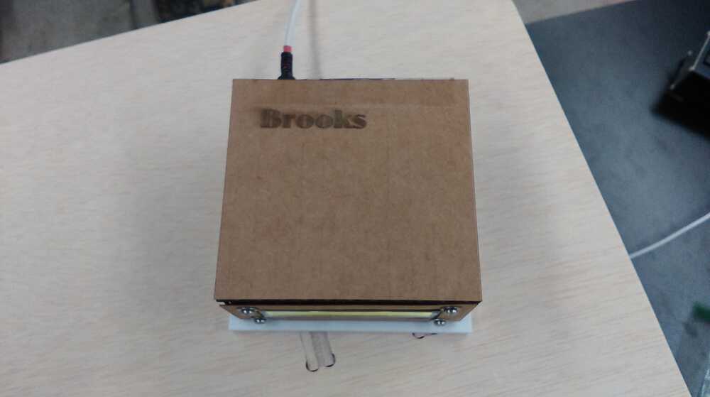
The end result is an adjustable standing desk converter that comes with a message-center, a small box with a screen that will display the ambient temperature along with a message that I can remotely change. The message-center automatically connects to WiFi and updates every few seconds.
This project was meant to be a gift for my wife to use in her office, where she's been wanting a standing desk for a while. Although the stiffness isn't ideal, I think that the desk is stable enough and can be adjusted to the correct height for her use. Ideally, I would add a separate keyboard holder and maybe a monitor mount later, along with a counterweighting system to make in-place adjustment easier, but I think that this model meets the basic requirements. The message center will allow my wife to check the room temperature, which is often too low, and will allow me to send her greetings throughout the day.
I believe this project was a success, and look forward to installing it in my wife's office after the presentation!