 Neil loves to remind that Core XY was produced by a HTMAA Alum! They have a great open source reference page which you can find by clicking on this image. This is where we started.
 descriptions

Step 1: Figuring out the Schematic
Once we decided we were going to move forward with Core XY for the motion system, we had to figure out how the mechanism worked. Turns out there's a number of different ways to do it, and where this aforementioned example crosses belt paths away from the stepper motors, TA Jake recommended that we avoided this method. TA Leo suggested we look to see how the 3d Printer Grid Bot Two manages Core XY.
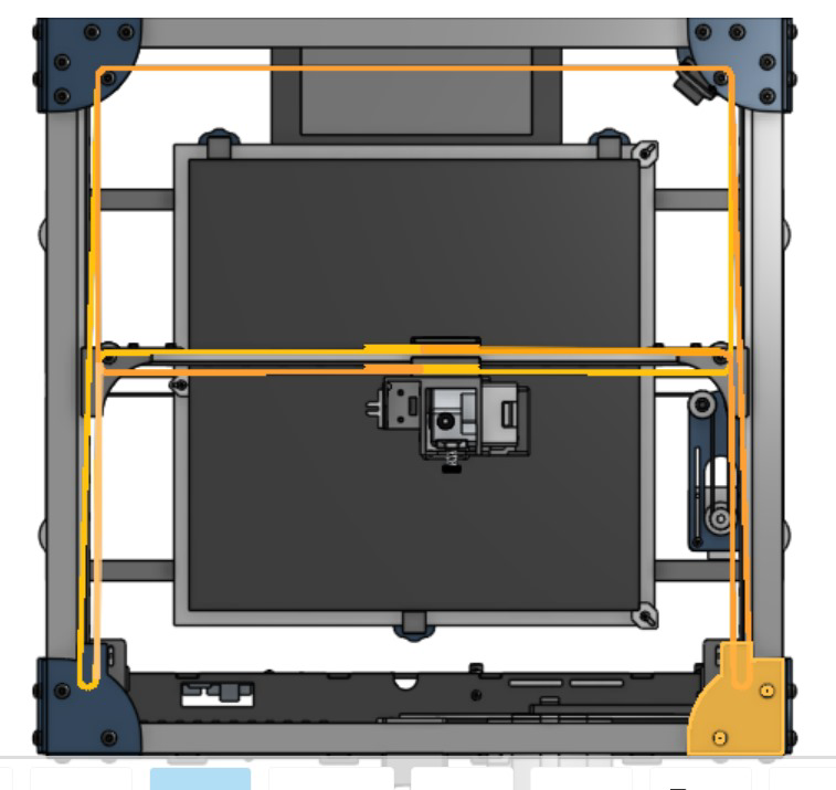 Grid Bot Two 3D Printer
At no point do the belts cross in this schematic. Figuring out the trick behind these belt designs can be tricky, so we thought it was best to try and model the belts to see how they were able to move past one another without causing any friction.
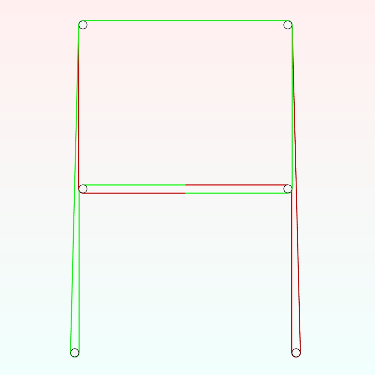
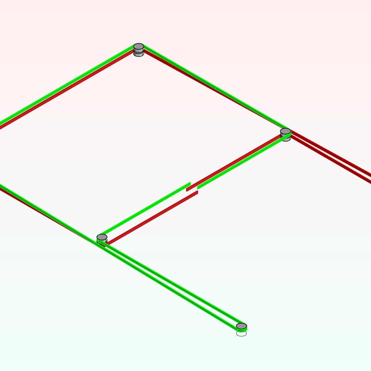
After modeling it was a lot easier to understand the finesse behind this design. The important details here are that the top four idlers are all orthogonal to one another, and they are all stacked idlers, having two per spindle. The bottom two are gears, and they are attached to the stepper motors. The one controlling the green belt is situated in a z-plane above the one controlling the red belt. And lastly, each of these stepper motors is offset the orthogonal axes of the top four-set by exactly 1 diameter + 1 belt thickness. This keeps the interior stepper leg of both the green and red belts perfectly straight with the interior idler legs above it, while creating a diagonal that prevents a belt collision near the middle idlers.
Step 2: Acquire the Parts
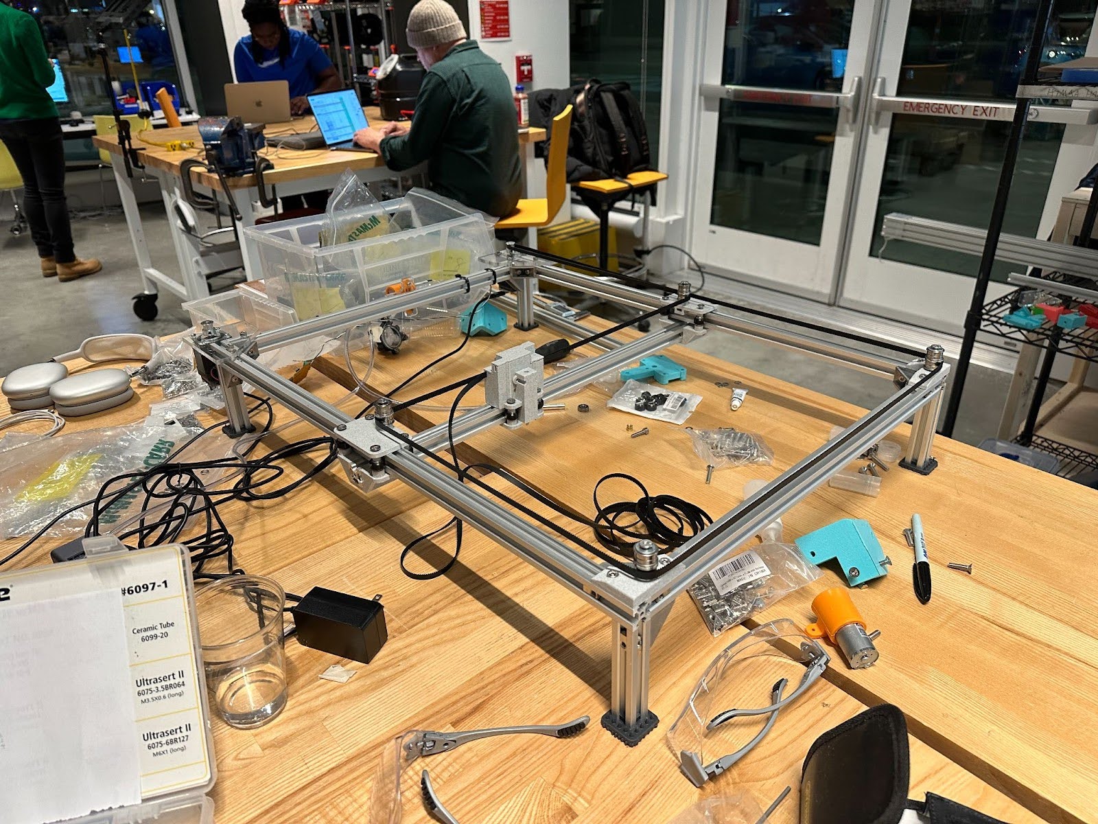
A lot of components go into making this mechanism, some of which are off-the-shelf, others of which we'll end up having to make somehow. Lucky for us, this machine does a good job at making use of many of the parts included in this week's kit. Let's take a survey of what we got and what we'll end up needing to make.
- [included in kit] 2 NEMA17 stepper motors
- [included in kit] 2020 V-groove aluminum extrusions 1000mm (framing rails)
- [included in kit] Extrusion Corner Brackets
- [included in kit] Extrusion Post-Install T-Nuts
- [included in kit] 5M GT2 Timing Belt 6mm
- [included in kit] 625 Ball Bearings (20 count)
- [included in kit] Washers M5
- [included in kit] 5M GT2 Timing Belt 6mm
- [included in kit] SHCS M5 Bolts x Various Lengths
- [included in kit] FHCS M5 Bolts x Various Lengths
- [included in kit] Standard 3D Printer Roller Wheels
- [need to fabricate] Sliding Brackets with Idler socket
- [need to fabricate] Corner Brackets with Idler socket
- [need to fabricate] Corner Brackets with Motor Attachments
- [need to fabricate] Z-Stage with Belt Clasps
- [optional but recommended] Little Footies with Spikes c;
INGREDIENTS:
 Starter Kit Pieces
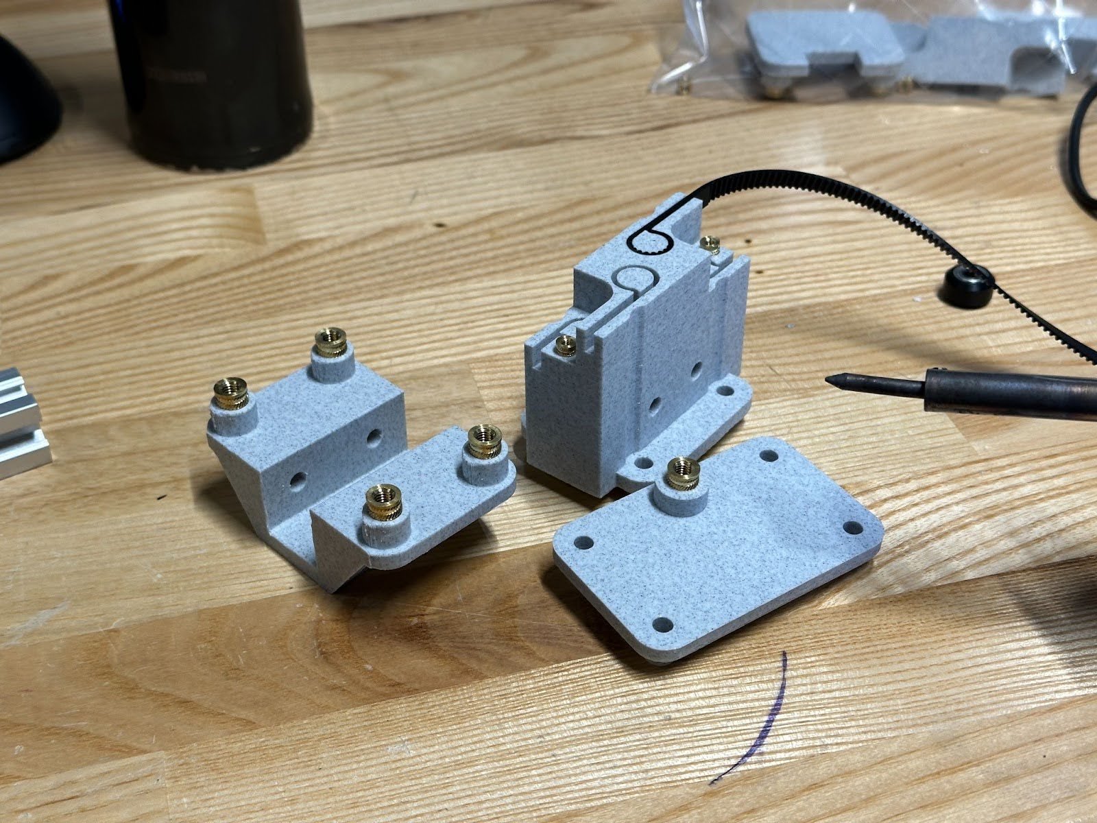
There were some example pieces that were provided one of which (the one closest in this photo) was used as a base for the sliding joints.
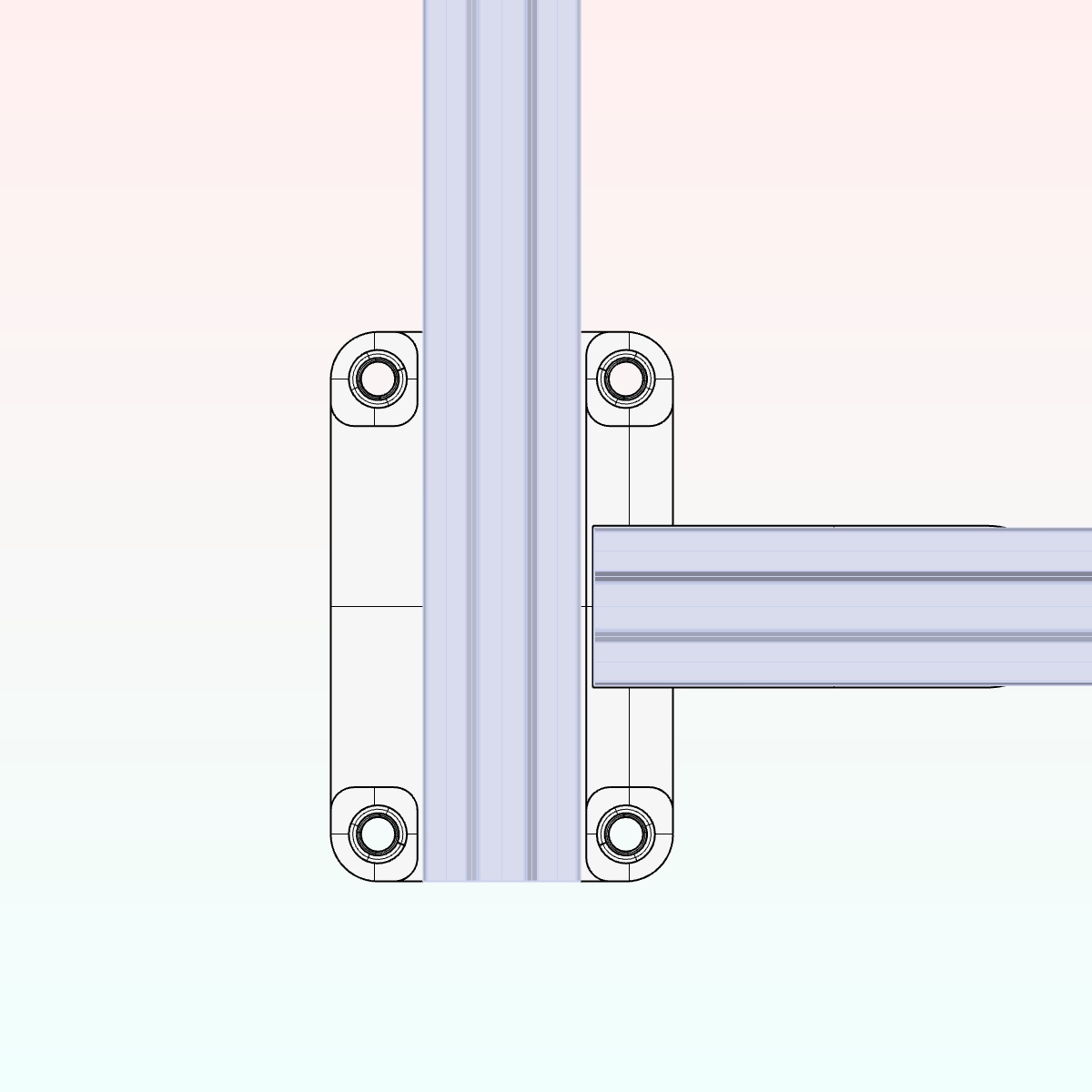
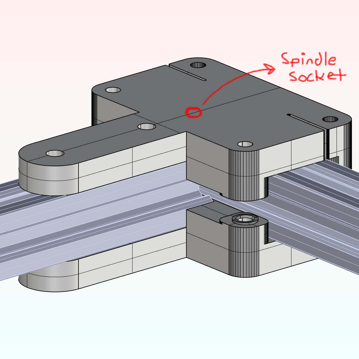
It was altered firstly adding an additional arm to receive the gantry arm, with a two socket moment connection to prevent rotational forces. An additional hole for the stacked idler's spindle socket, and sandwiching them to produce a greater rigidity in the joint.
 Corner Bracket with Idler Socket
 Spiked Footies to Ward Off Enemies
 Initial Z-Stage Design
These were the first round of 3D Prints that went out. There were some issues: the original print file wasn't designed for sandwich, which ended up causing some looseness in the joint. Also, the Z-Stage was designed with a post-tensioning mechanism which increased its size considerably. This ended up being a problem because the larger the Z-stage is the smaller the print bed ends up becoming. It would be better to post-tension the cables elsewhere.
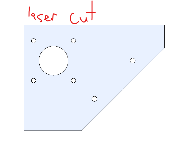
For the sake of quickness, the stepper motor joints were just cut out of a piece of acrylic.
Part 3: Assembling the Parts
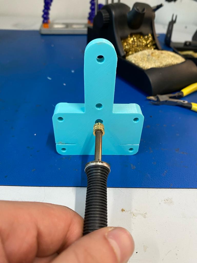
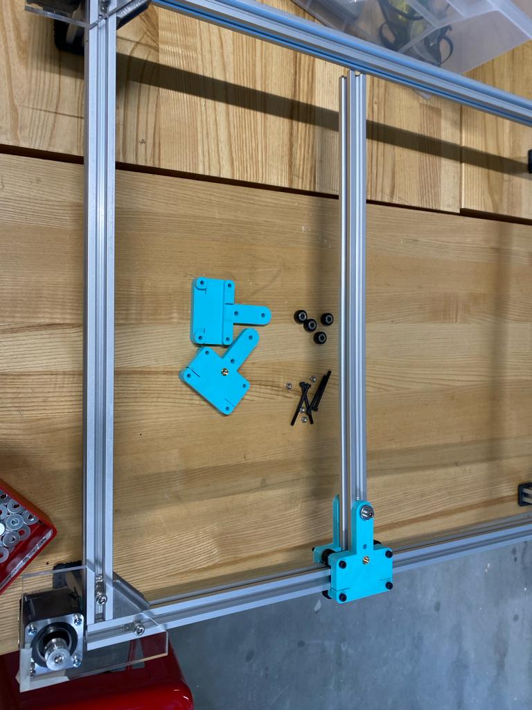
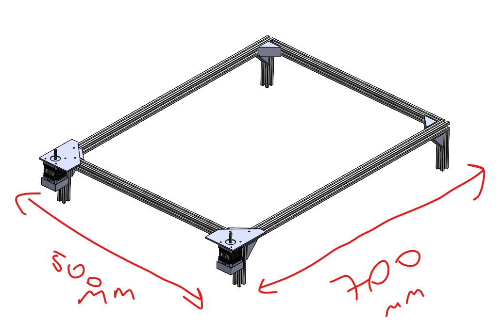
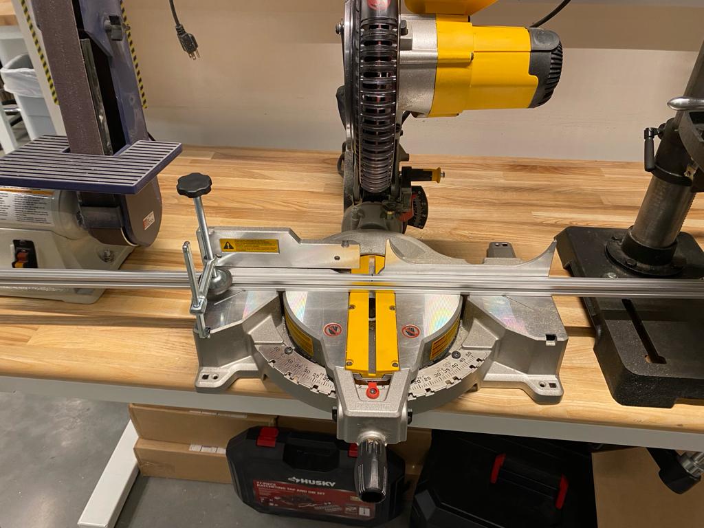
We chopped down the extrusions to the sizes we needed. We used a soldering iron to insert our threaded sockets into the 3D printed piece, which melts the PLA making a snug fit for the idler. From there we were able to make a sandwich joint.
It slides!
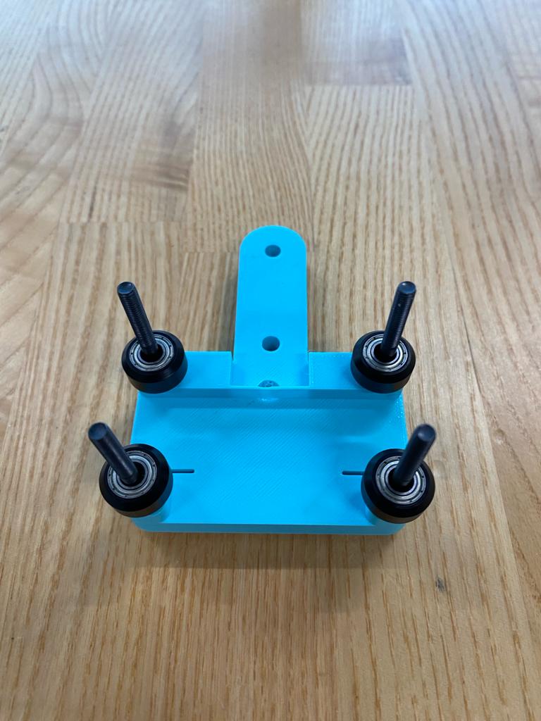
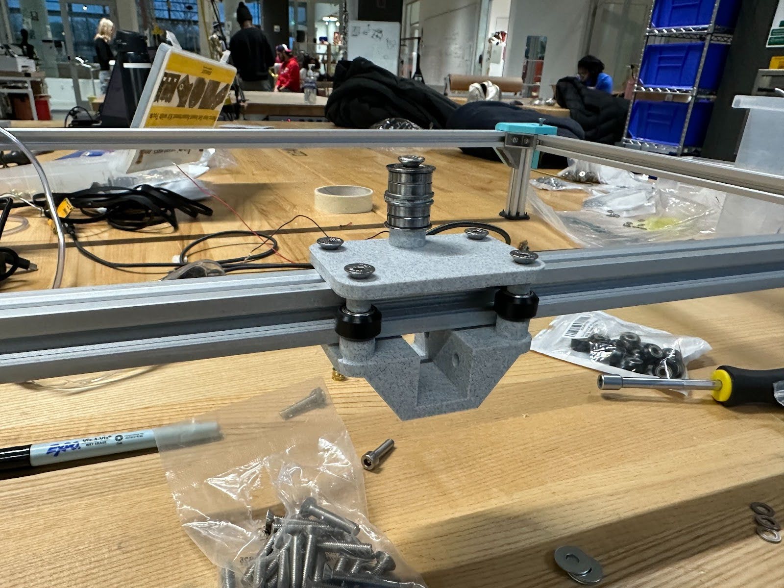
 Adding the Idler
After testing out the first set of 3Dprints we discovered a number of ways we could improve the design. We went back to the drawing board to design tighter joints, and a more compact Z-stage.
 New Assembly
 New Assembly
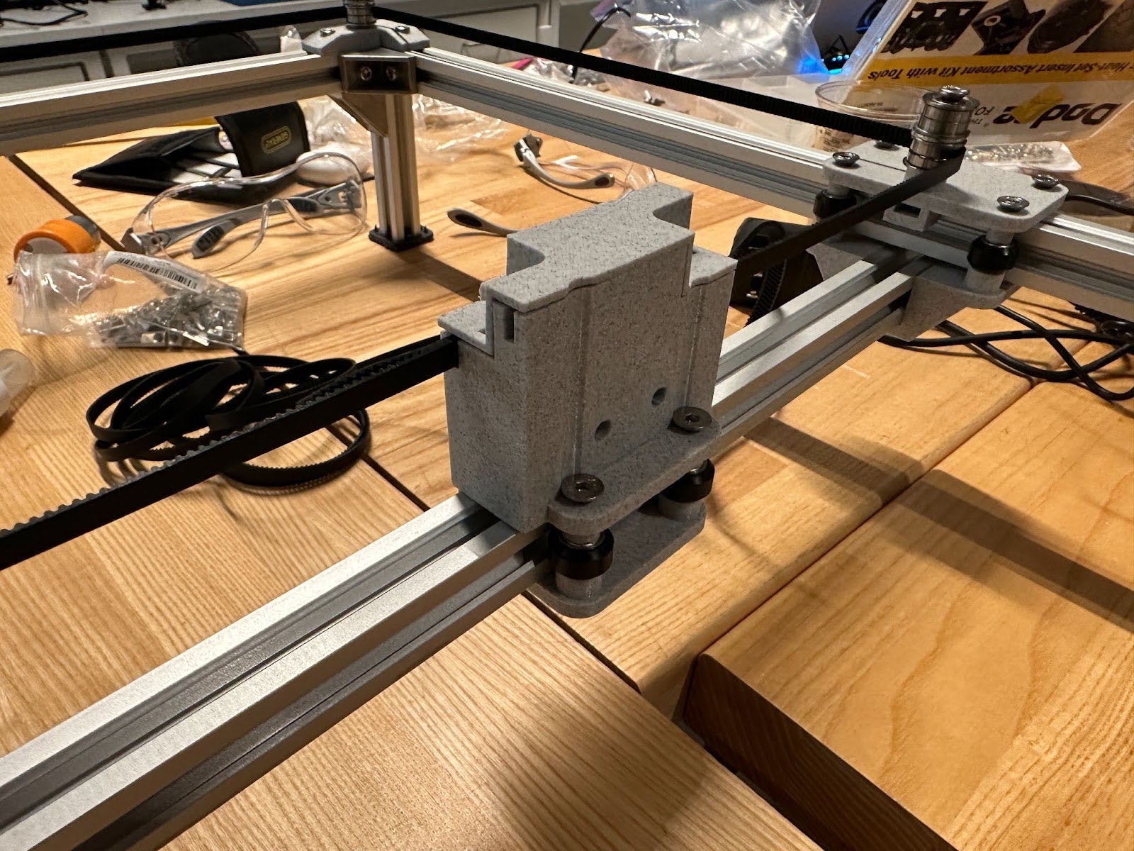
Round Two! It's coming together!

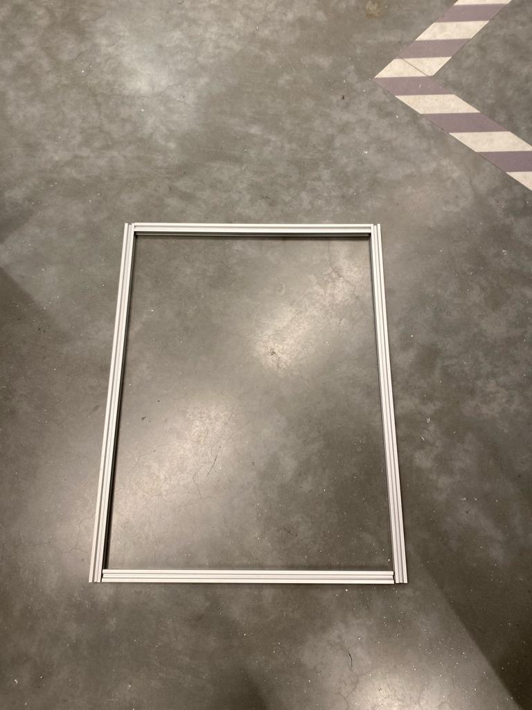
The new 3D prints were able to slim down the z-stage form factor a ton by adding a clean belt locking loop detail, but this meant that we had to find another way to post tension the cables because they were initial quite loose. We also were in a bit of a pickle because the remaining belt we had was about 1 and a half inches too short to complete its loop. We fixed both of these issue by sliding this backside extrusion in, attaching the belt at the length it was able to reach, and then pulling the entire extrusion back while tightening down the bolts to post-tension each of the belts.