For a thought dump of my inspirations, design process, iteration and ideation that brought me here, visit the void.
I chose to make a wearable controller for a musical instrument, however rather than make an actual glove,
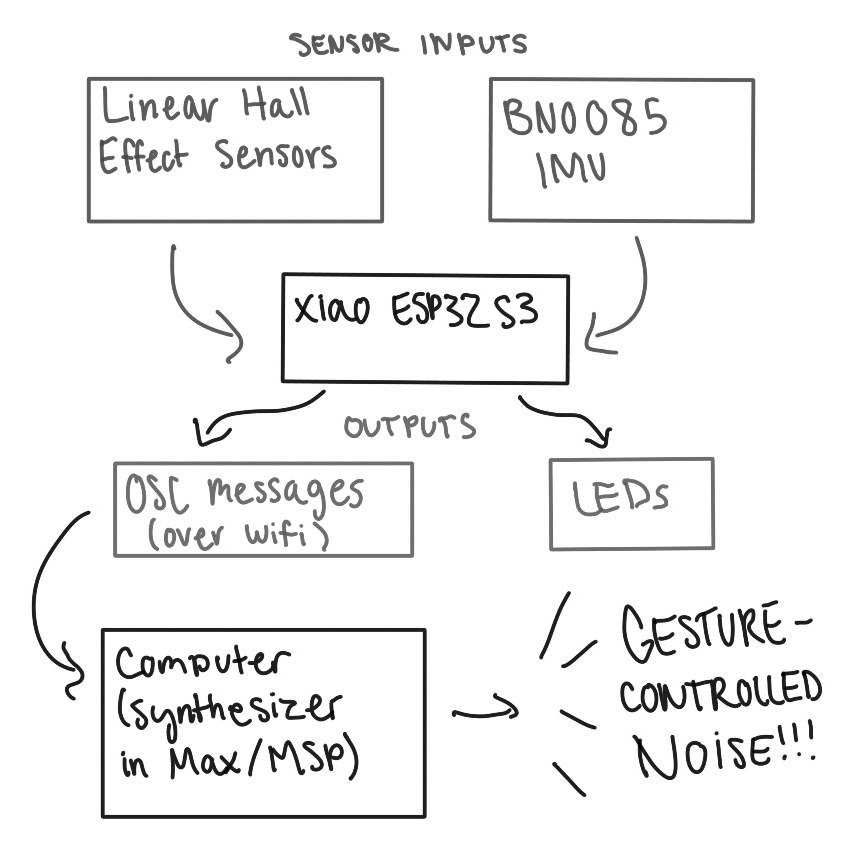
I wanted to make a more minimal jewelry-inspired enclosure. After some experimenting, I chose to utilize hall effect sensors and an IMU for finger bend and hand position tracking. The intention was to map these controllers to some kind of synthesizer I'd make in Max/MSP.
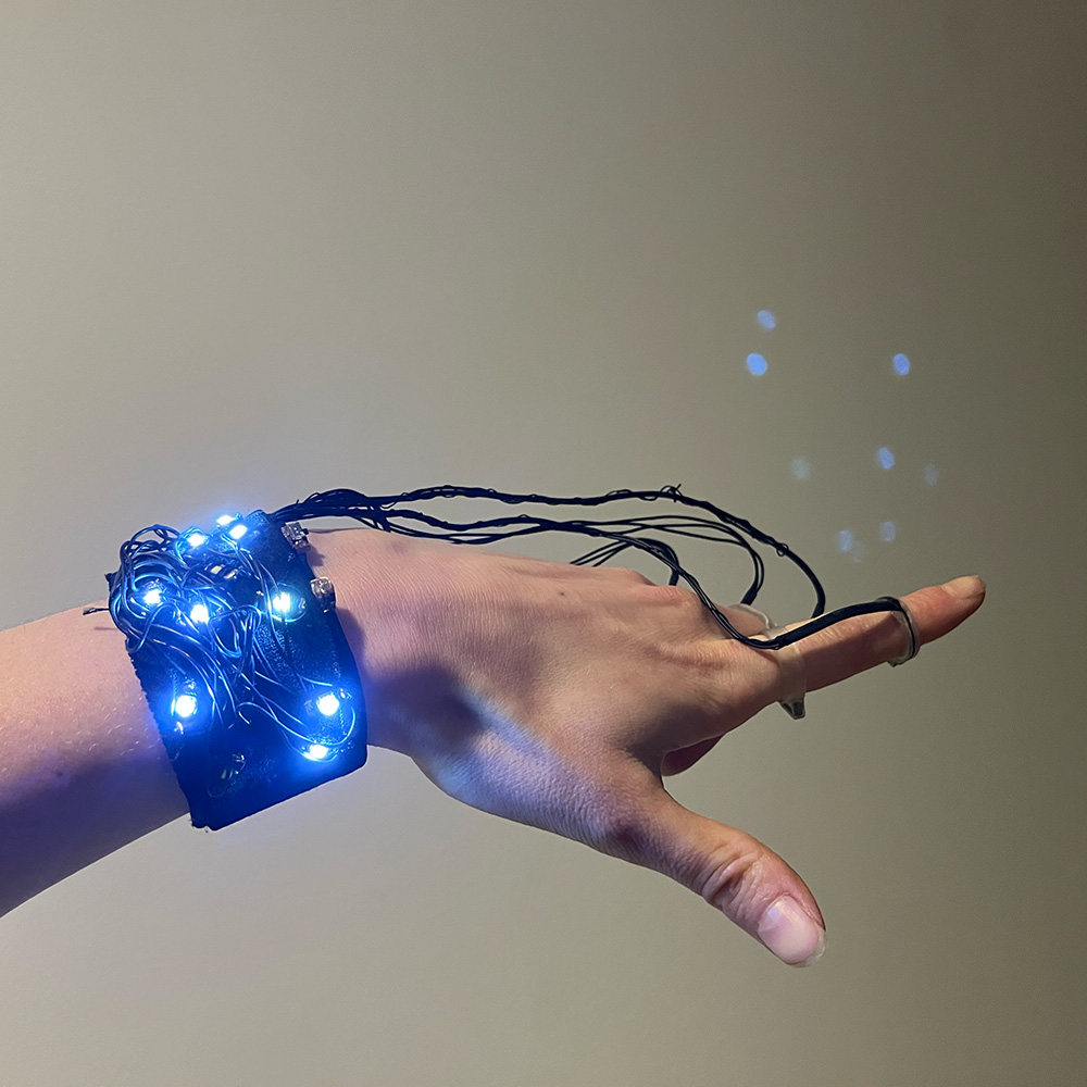
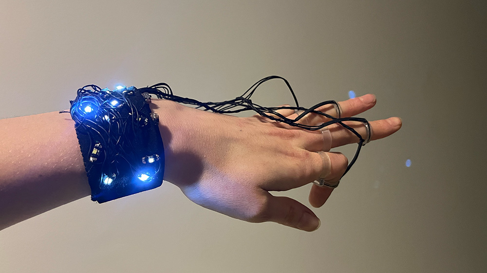
Aesthetically, I wanted to do something which capitilizes on the beauty of electronics and shows off the wiring and components in an exposed-yet-robust way. I also wanted to include LEDs because who doesn't love things that light up (and to provide visual feedback of
the sensor data).
These sketches were developed in mid-November after I had already done a fair amount of prototyping for my design. To look at my original version, visit the void.
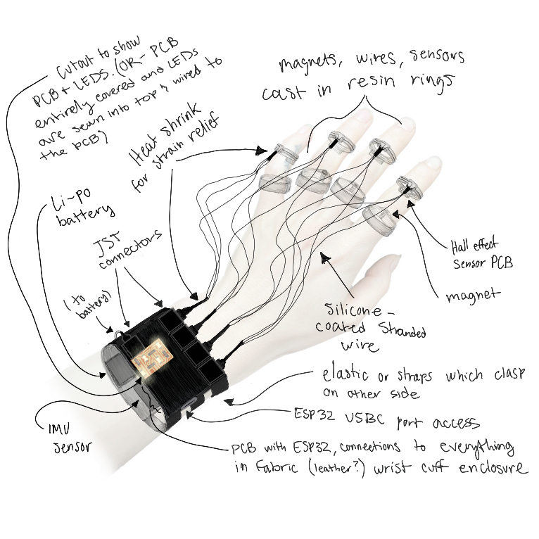
The sensor rings are the real centerpiece of this project and took a very long time to develop! I spent months iterating to achieve the final form factor, experimenting with a variety of materials, and failing many many times. You can find more (admittedly spotty) documentation on that in the void, but if I were to break it all down here it would be unreasonably long so I will give a quick summary of how I got to this point with the preface that behind this are countless hours of trial, error, and revision.
At the very beginning, I wanted to make a fabric enclosure. Then I shifted to sheet metal and making something armor-esque. During Molding and Casting week , I learned to make laser-induced graphene (LIG) flex sensors and decided cast those in rings. For the next week, input devices , I decided to try hall effect sensors just in case, and much to my surprise, I loved it. So I decided to pair hall sensor rings with magnet rings as a way of sensing finger bend. After that change in direction, I began the process of developing a final design. Following the idea to stick sensors inside a mold and cast rings, I iterated through several designs for the ring molds, first making SLA printed molds, then milling molds in wax, but after that heavily anticipated and time intensive process went comically poorly, I had to reroute. After talking to a few TAs, I decided to use the formlabs SLA printer to create "shell" rings which the PCBs and magnets would fit into. I made a few of these before settling on a final design. The designs are parametric, meaning I can easily change the diameters to fit different fingers. Access the design in fusion here.
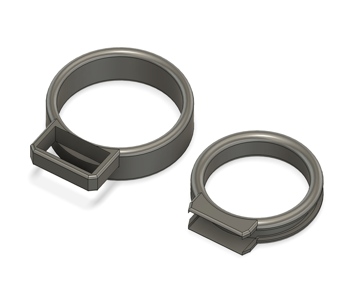
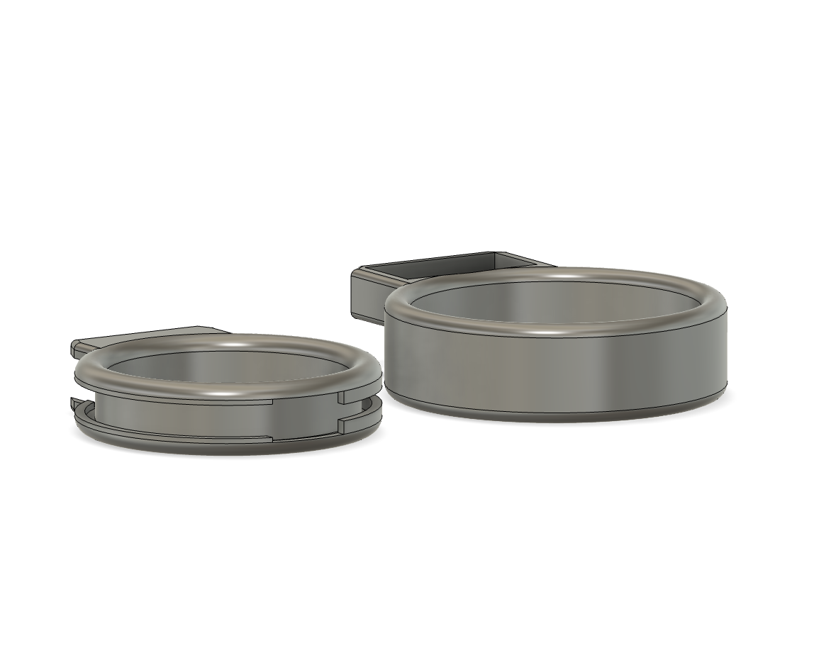
My magnet rings went through several iterations- I started out using cylindrical magnets but switched to rectangular ones to have a wider surface area on top. I made rings that had channels on the back for the wires to feed through but scrapped that because I didn't like it. I tried different thicknesses. I even tried making square rings to see if it would limit the sliding around that tends to happen and leads to the magnets moving out of alignment, making the bend sensing mechanism useless. While the square ring idea didn't totally stick because they are a bit clunky, I still use the square one I made for my middle finger because the knuckle on that finger is much wider than the part where the ring sits so a "fitting" round ring is more prone to sitting loosely and sliding around (square ring CAD not pictured above but it is included in the linked file.)
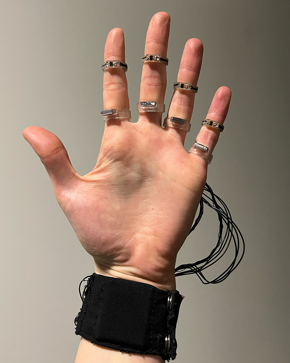
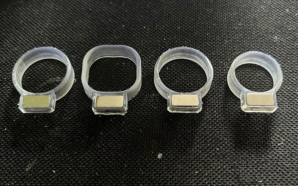
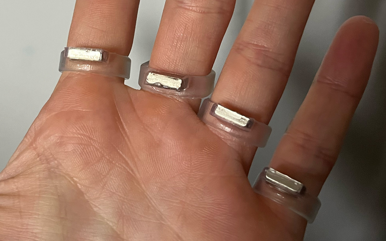
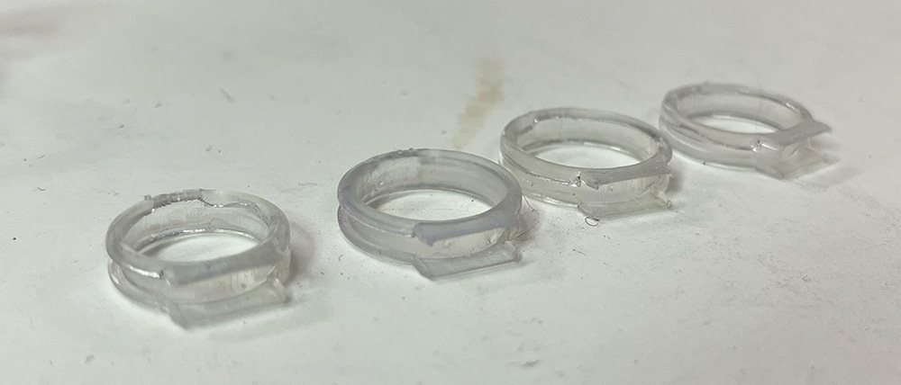
The process of making them is: print the rings on the SLA printer, remove the suports and press the magnets in so the top of the magnet is somewhat flush with the top of the slot (and making sure the magnet poles are all facing the same way!). It takes a bit of force and patience but the magnets sit snugly. After that I run the rings through a 10 minute wash and 5 minute UV post-cure cycle @ 60 degrees celsius. Then I flip the rings over and fill the bottom of the magnet cavity with a bit of UV resin and cure with a UV flashlight. Here are the final rings:
To learn more about the sensors I'm using and the schematic, look at my input devices documentation.
Obviously these rings were a fair bit more complicated than the magnet ones and took quite a while to get right. I can't count how many iterations there were of each element in the process, but it took several weeks to get to this.
While I'm documenting the final process here and it may seem straightforwards, that is really just a product of how much practice I got from all
the prototyping!
One of the biggest questions I kept running into with this project was "but how can I make this even smaller???". Making a ring-sized hall effect sensor PCB was one of my favorite parts of that. This is the one I used in my final design:
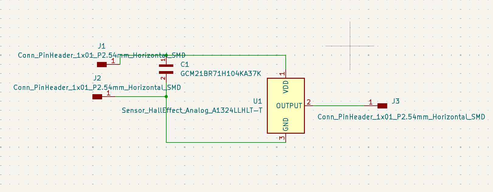
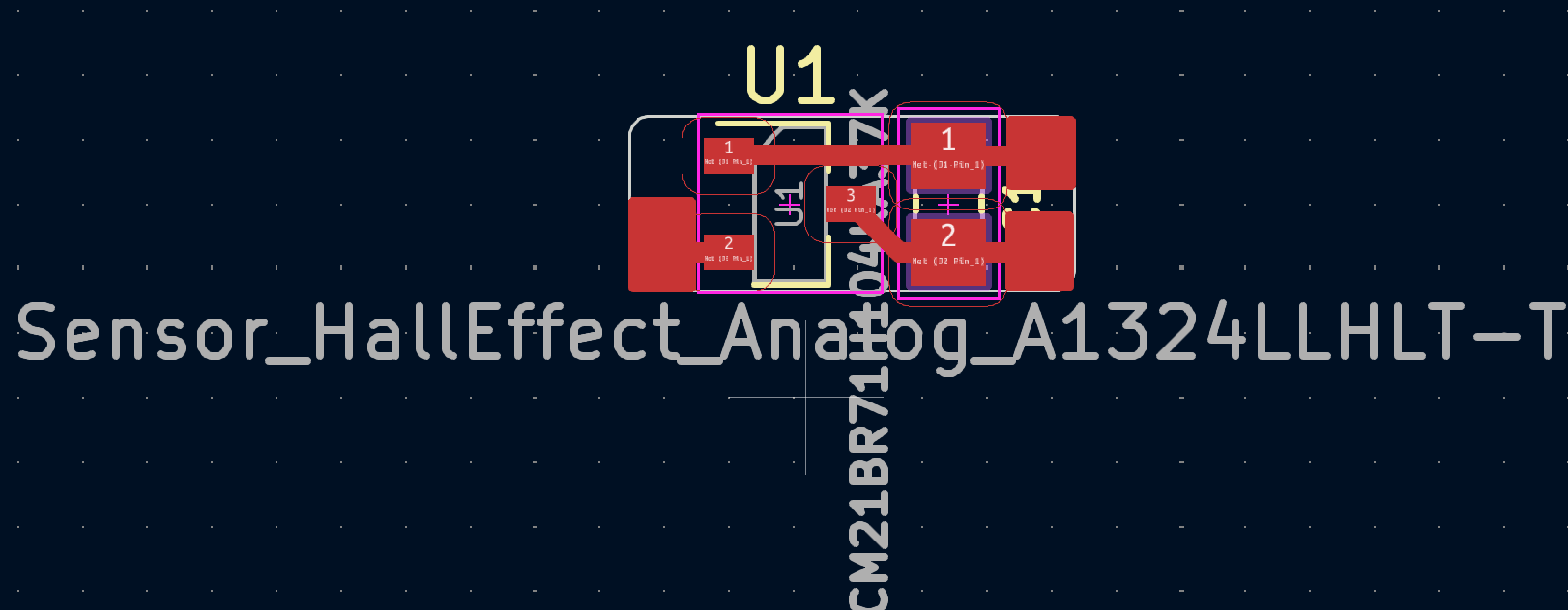
Download the kicad project here. As you can see, I customized the pad size/shape for the wires just to make things as compact as possible- while still reasonably hand-solderable.
I milled the PCBs with the carvera, using Quentin's gerber2img converter and Mods to generate the Gcode.
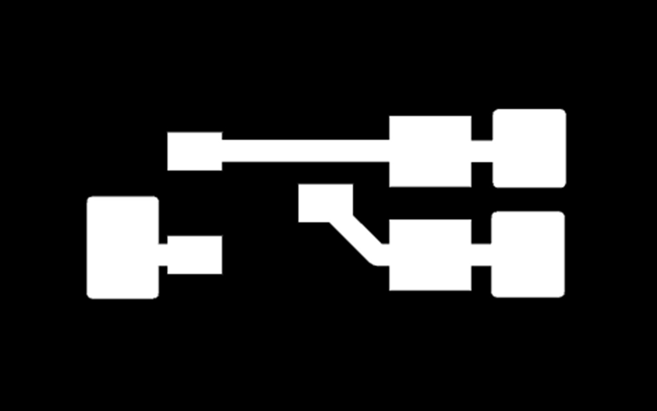
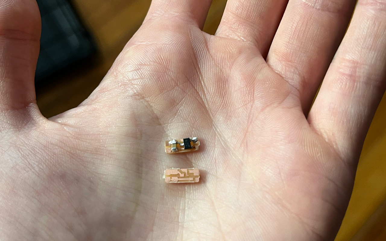
As you can see, it's very small! Soldering them takes practice and patience. I also file down the backs of these PCBs so they protrude less from the enclosure. The amount of material I remove varies but I generally aim for getting the PCBs down to ~2/3 to 1/2 their original thickness.
The process of printing the rings is similar to the magnets- print, remove supports, wash 10 min, and post-cure 5 min @ 60 degrees celsius (though usually I only did it for ~3 min because they get more cure time later and excessive curing will yellow the resin). I found that printing the rings on their side turned so the back (side the wires come out of) is pointed down is by far the best way
to do it because there will be no supports needed in the part where the PCB goes. This is important because, for one, that part is very thin and can easily break when removing for supports (which is a bit tougher on the SLA printer than FDM in my experience). For two, any stubs/ irregularities left behind from the supports will negatively impact the fit of the PCB, and it is a very tight fit, so that makes the process harder.
The freshly printed and post-cured rings looked like this:
Note that it looks like the edges of the wire tracks are broken in some spots but they are not, the resin just settles unevenly in the small cavity there and it looks a little odd before I put the wires in.
With the shells ready to go, I attached long silicone coated stranded wires to the PCBs and popped them into the enclosures.
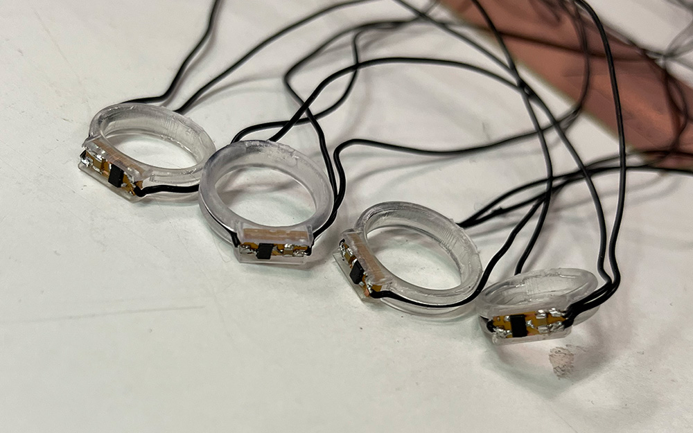
From there, I applied a bit of resin to the top of the PCB, filling it up to the top of the shell walls, pushing it into the cracks and smoothing with a popsicle stick, then cured that with the flashlight. For some of the rings I also partially did this with the wires to hold them in their slots better to make the next part easier.
Next was adding the heat shrink. I fed the wires through a piece of heat shrink, one at a time so I could label the ends with masking tape and keep track of what was what for soldering them later. With all wires through, I slid the tubing up as far as I could get it into the slot on the back of the ring. Before heating it, I tried my best to get the wires lying flat in a row so the heat shrink portion would be neat and flat. I did this right for 3/4 rings but the middle finger has a twist in it.
While shrinking the tubing with a heat gun, I made sure it bent the right way, angled so the wires would point down my finger.
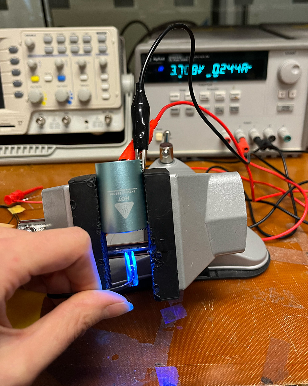
After that I started the process of working my way around each ring to fill everything with resin and cure it. This involved smoothing resin over all of the wire slots and scraping off excess around most of the circumference, as well as carefully layering on extra around where the wires come out to make sure that joint is especially supported and secure (you can see I already did this part for the middle finger in the photo above). I also added extra resin to fill the points on the side of the PCB where the wires bend down as that is another point which benefits from extra structural security. Before getting to this part, my UV flashlight battery died so I hooked it up to a power supply and put it in a vice so I could just hold the rings underneath it.
This part is really more of an art than an exact process- each ring comes out a bit different. After flashlight curing, I stuck them in the formlabs UV box for a few minutes just to fully harden everything. I noticed a few divots that could've used more resin afterwards, but they were small and structurally insignificant enough that I decided to leave them.
Developing the rings had been such a focus for me for so long that besides envisioning a specific layout and heavily workshopping/iterating on my wristband PCB design, I didn't really get too deep into making it until the final few days. Making this portion took a lot longer than fabricating the rings (as the documentation will show) and was more challenging than I expected.
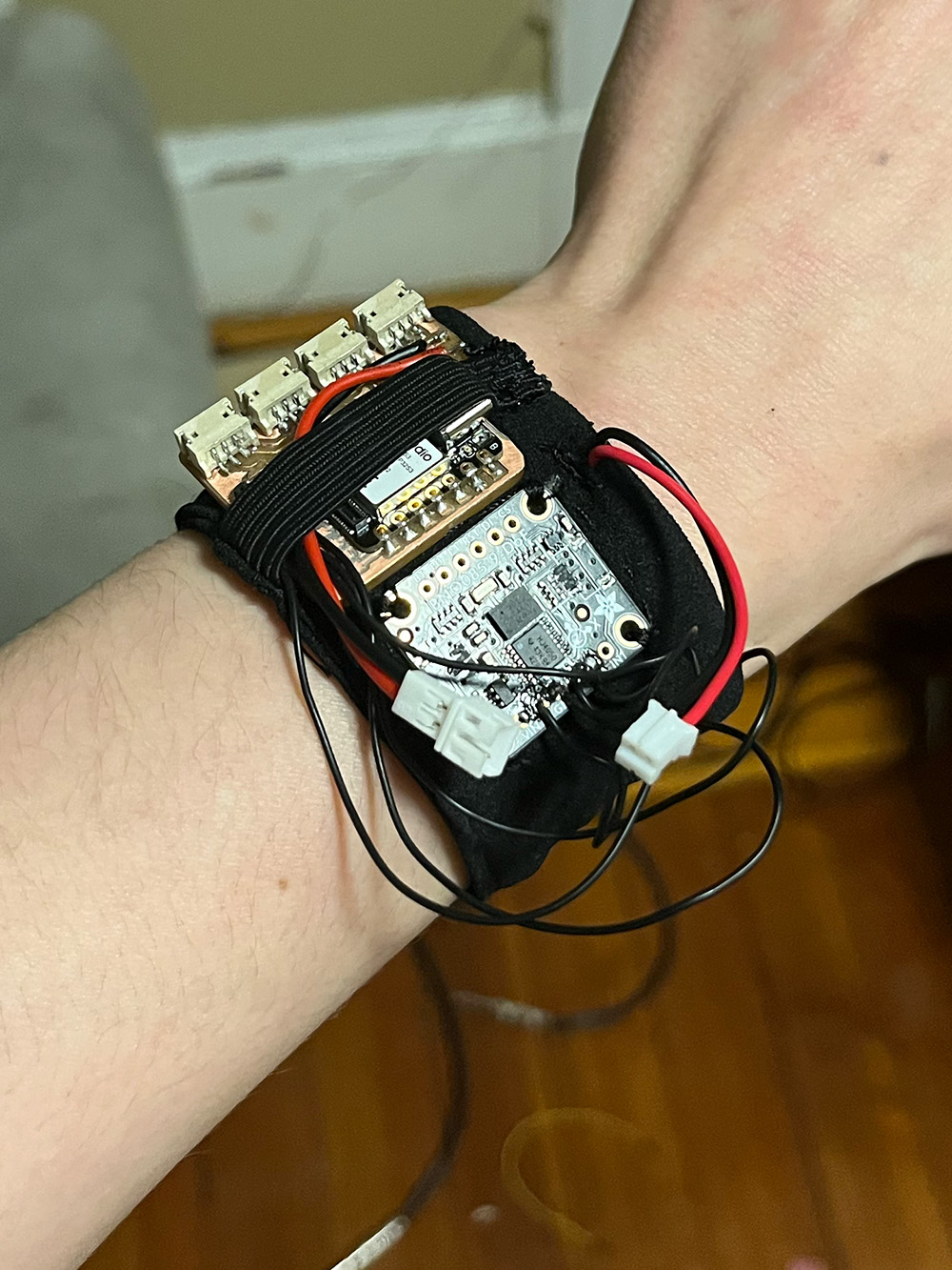
Until the last few days of this project, I was so sure I'd be using JST connectors for the rings. I did this for my prototype board which you can see in my week 12 documentation. Though that board used the larger PH connectors, I was planning to switch to the smaller ZH variety and spent a while working on the layout for a board compact enough to not be bulky on the back of my wrist but still fit those connectors. And I actually ended up making it, what I thought was my final PCB:
I'll get more into explaining the layout/ design details for my actual final one later. But with this PCB, I got to work making the wristband and encountered a lot more difficulty than I expected getting started. Before taking this class, I used to approach creating things from a very intuitive, figure-it-out-as-I-go process, but this class has taught me a lot about planning, and I was very much in that mindset. However, I had to abandon that just a bit to really get anywhere with this, so it turned into a hands-on experiment and spiral develop as I go kind of process.
After experimenting with some scrap fabrics I had on hand and getting absolutely nowhere, I remembered the box of old clothes I was planning on getting rid of under my bed and found a shirt with a neck strap that had a lot of potential. It's essentially just a tube of slightly stretchy fabric with a thin layer of facing on the inside that would be very easy to recreate.
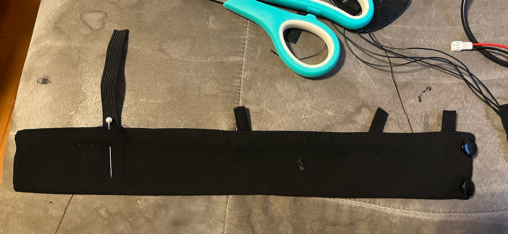
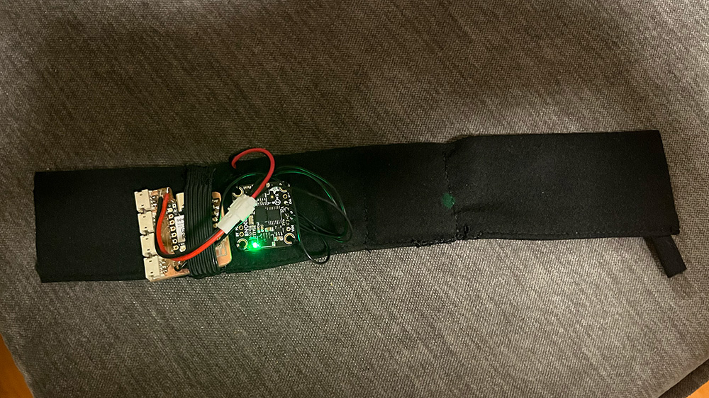
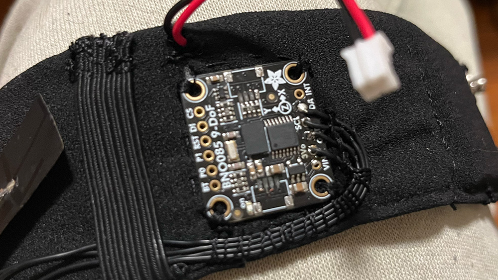
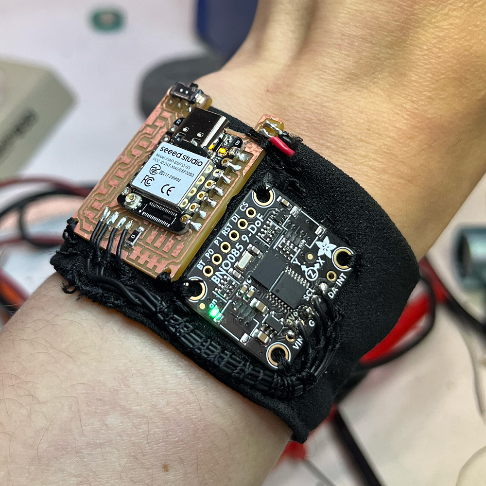
At that point I had already settled on trying to make some variation of "pockets" for all of my components, particularly for the battery (so I could remove and change it out as needed) and the xiao PCB so I could access the USB port and onboard boot/reset buttons for programming and battery charging. This evolved into sewing the battery in but using elastic to hold the PCB in place while still leaving it freely removable. After testing out how things felt on my wrist in different palcements, I decided to make some changes to my original layout idea, rotating the PCB 90 degrees and putting the BNO085 on top of the wrist next to it.
I slid the battery in and sewed it in on both sides, routing the connector cables out towards the PCB location, sewed the elastic and the BNOO85 in place, and the result looked like this:
Happy with how that was going, I cut it to the right length, fused the ends of the tube with some strips of iron activated fabric glue, and attached snap buttons so I could easily put it on and take it off.
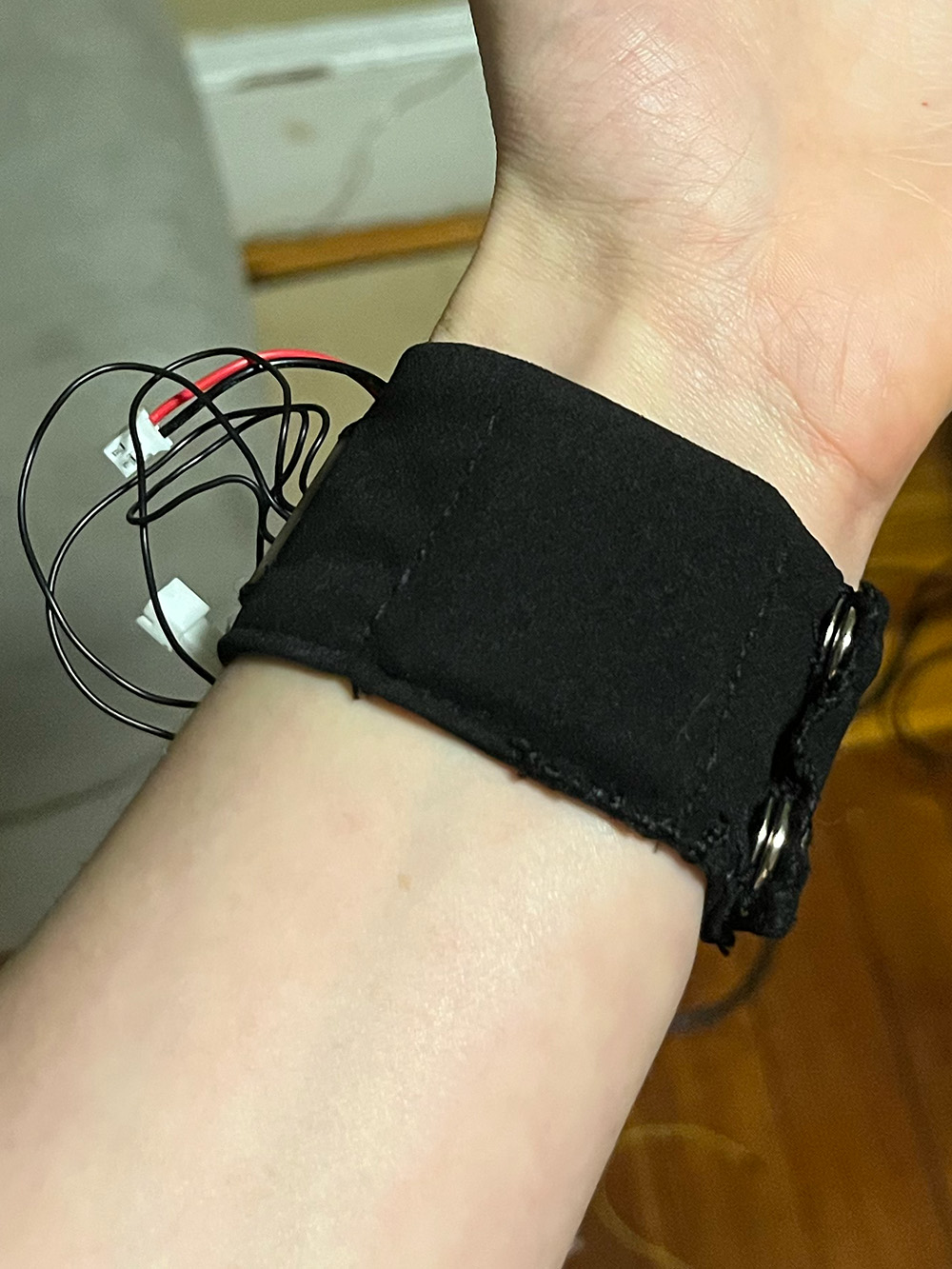
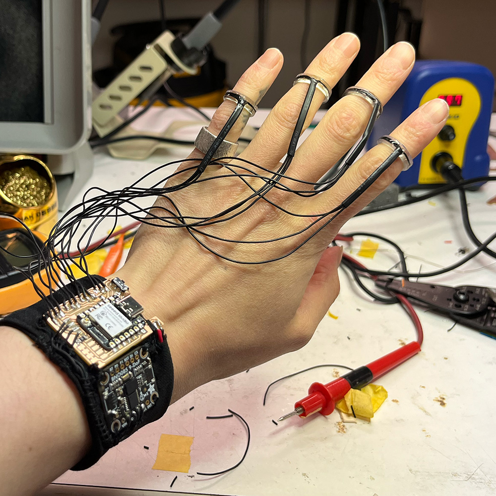
From there I decided to sew around the wires from the BNO085 to hold them in place and prevent them from getting pulled on. I throught it looked super cool!
At this point I was mostly done working for the day and concluded a few things:
- plugging in and unplugging the battery was annoying and I'd much rather have an on/off switch.
- the JST connectors were bulky, ugly, and annoying to work around, and I knew realistically in practice I'd just leave the rings plugged in all the time anyways
- something about how the sewn down wires looked was really inspiring to me
- if I soldered the ring wires directly to the board, I'd be able to make a less bulky enclosure, and sewing those wires in would be a great way to secure them.
- if I did this I could also just sew the board directly in rather than making it removable
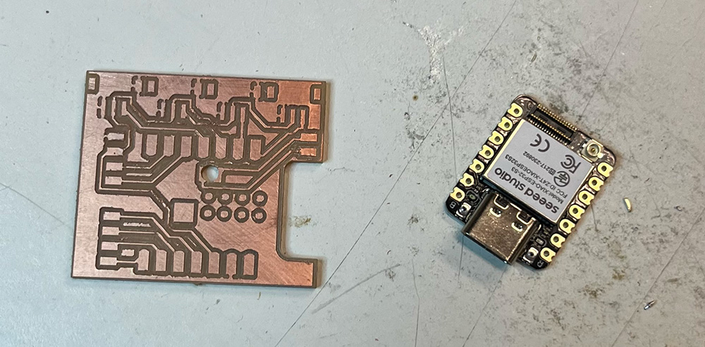
Making all of this possible would require making a new PCB. So the next day, that's exactly what I did. Download the kicad for my final design here.
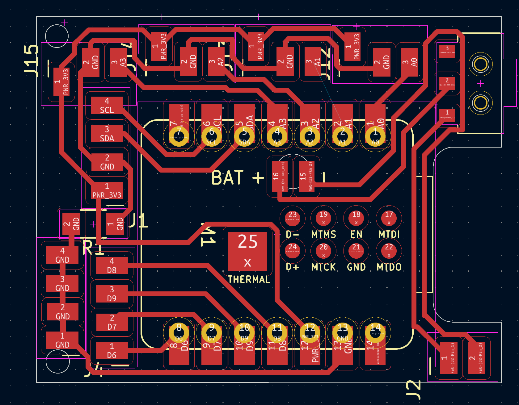
Can you spot the missing trace?
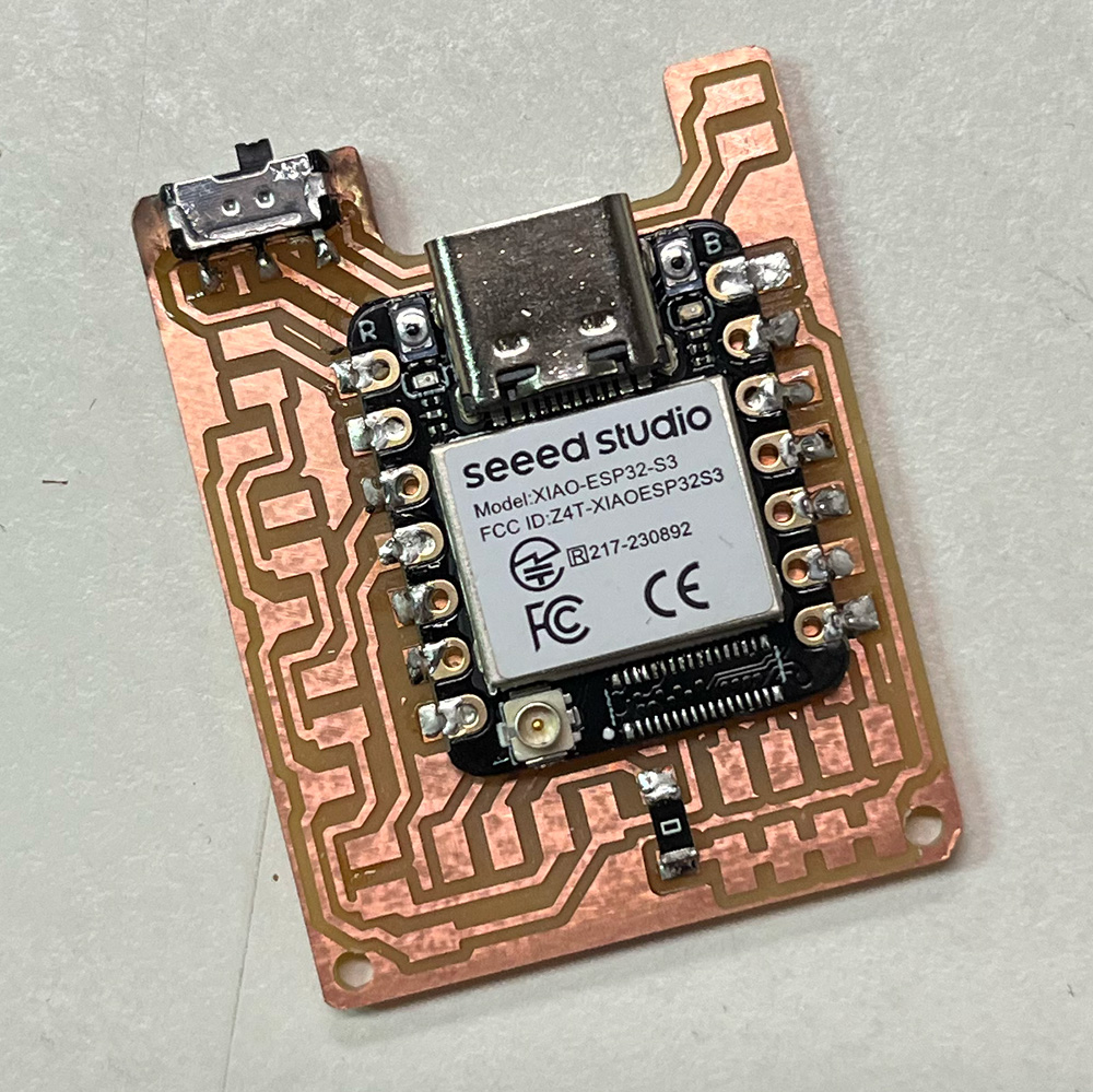
A lot of thought and care went into this layout (except for that one missing trace apparently), so I'll point out some of my favorite features. The battery connection pads are on the bottom of the board, which normally entails solder paste and heating that, but Quentin said that can sometimes damage the buttons on the xiao and he'd seen many people cut out a hole and feed wires through. I didn't want to do either of those things, so I had the idea to add a circular cutout over both pads so I could pre solder the pads (on both the board and the xiao), then line up the xiao, flip over the board, and fit the iron tip through the hole to heat the pads and make a connection. This was a bit challenging to execute but worked really well! If you try this, I'd recommend testing everything thoroughly with a multimeter before proceeding, and make sure the xiao is well supported while you do this, since the pads are small and will rip off easily. When switching from JST connectors to pads for the ring wires, I customized the footprints to downsize the pads a bit and offset the 3v3 pads so I could snake traces around without adding width to my board (since I really wanted this version to be narrower than the last one.) I added holes on the bottom corners to make it easier to sew into place as well.
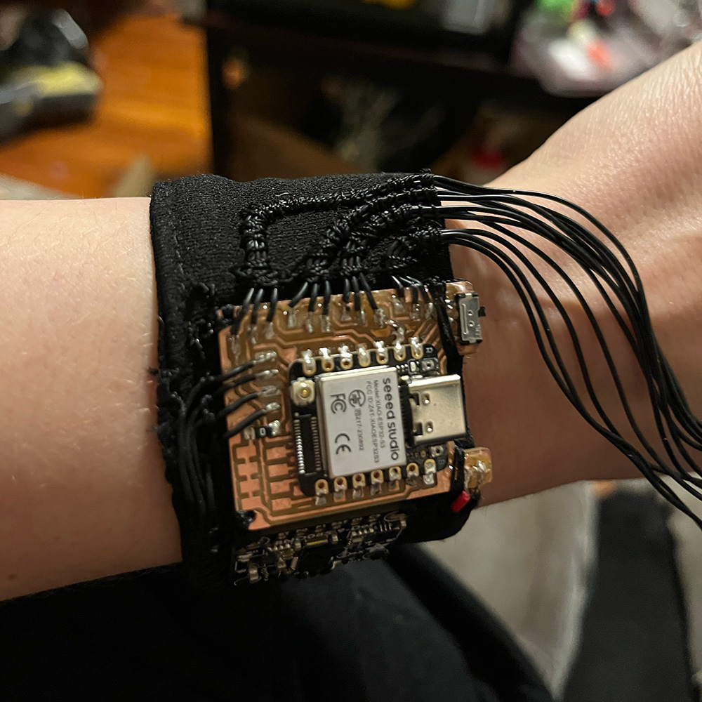
When soldering to the board, I applied UV resin all around the switch because it takes a fair amount of force to switch and I wanted to avoid placing any strain on the solder pads. I then sewed the PCB into place, soldered on the BNO085 wires and the battery wires, and confirmed the battery/switch worked (and that the IMU was connected properly)
From there I was able to solder the ring wires on and sew them in. After uploading my code to the xiao and testing my sensors (and then adding in a piece of wire to fix the missing trace which I had somehow failed to notice until this point in time), I put a layer of resin over the connections to secure them. Though not shown in the below pic, it's worth noting I added even more resin to the ring wires, along edge of the board and onto the fabric up until slightly past where the thread wrapping starts. I noticed this was a point of flexion that may cause wire strain, so I intentionally cured the resin while wearing the wristband so that it would follow the shape of my wrist and sit comfortably.
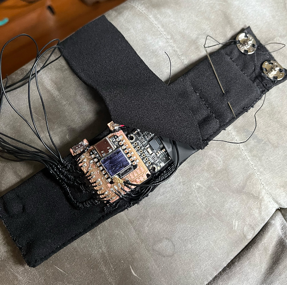
I spent a long time agonizing over how to approach this part before actually doing so. I wanted to the microcontroller to be covered but accessible and had left myself very little room to work with. I considered leaving it exposed and tried blacking out the sticker on the back to see if that would look better, and fiddled with various concepts that went nowhere until I decided to just start sewing on a cover flap and go from there. My plan was to leave enough space open at the top that the flap could be pulled back to make the necessary things accessible.
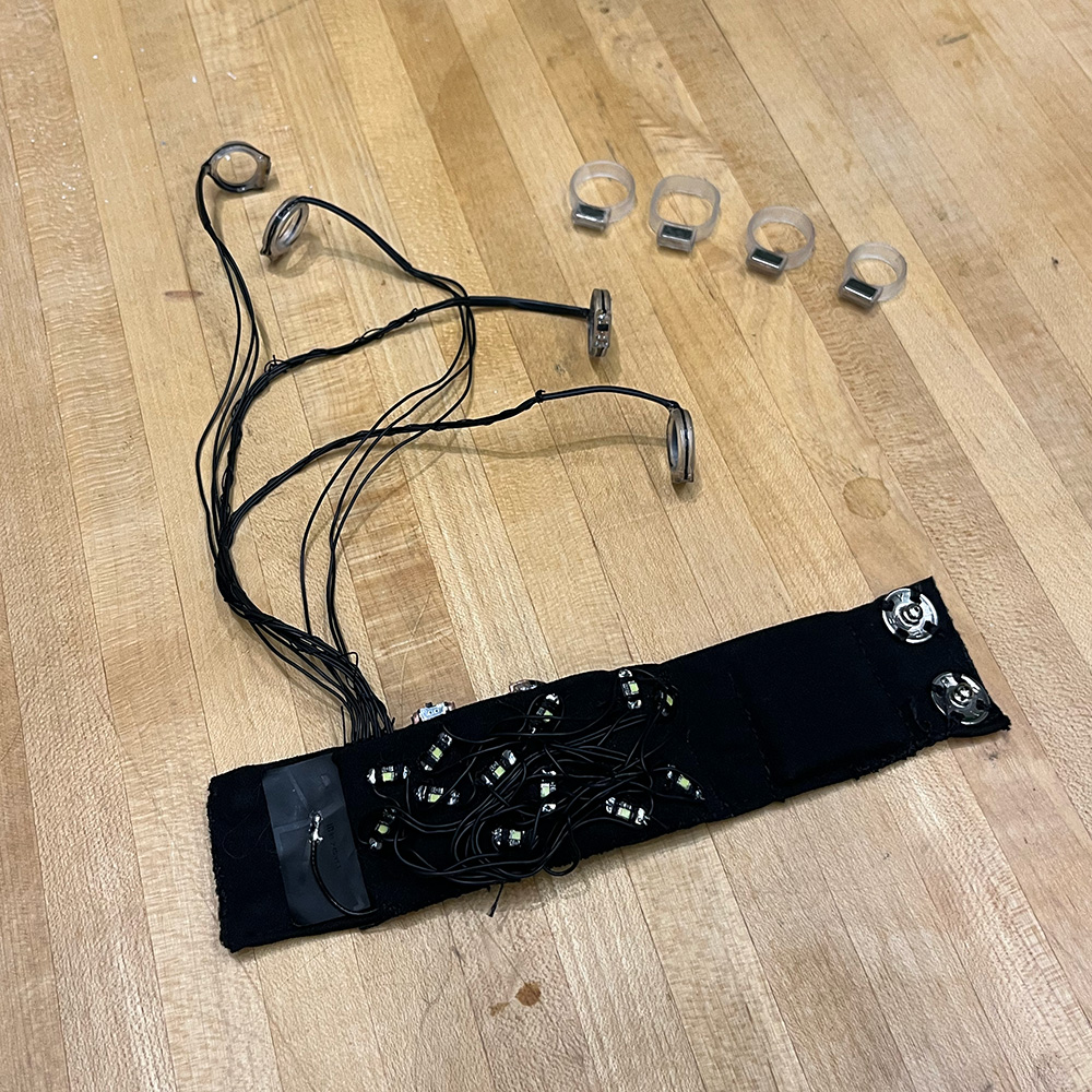
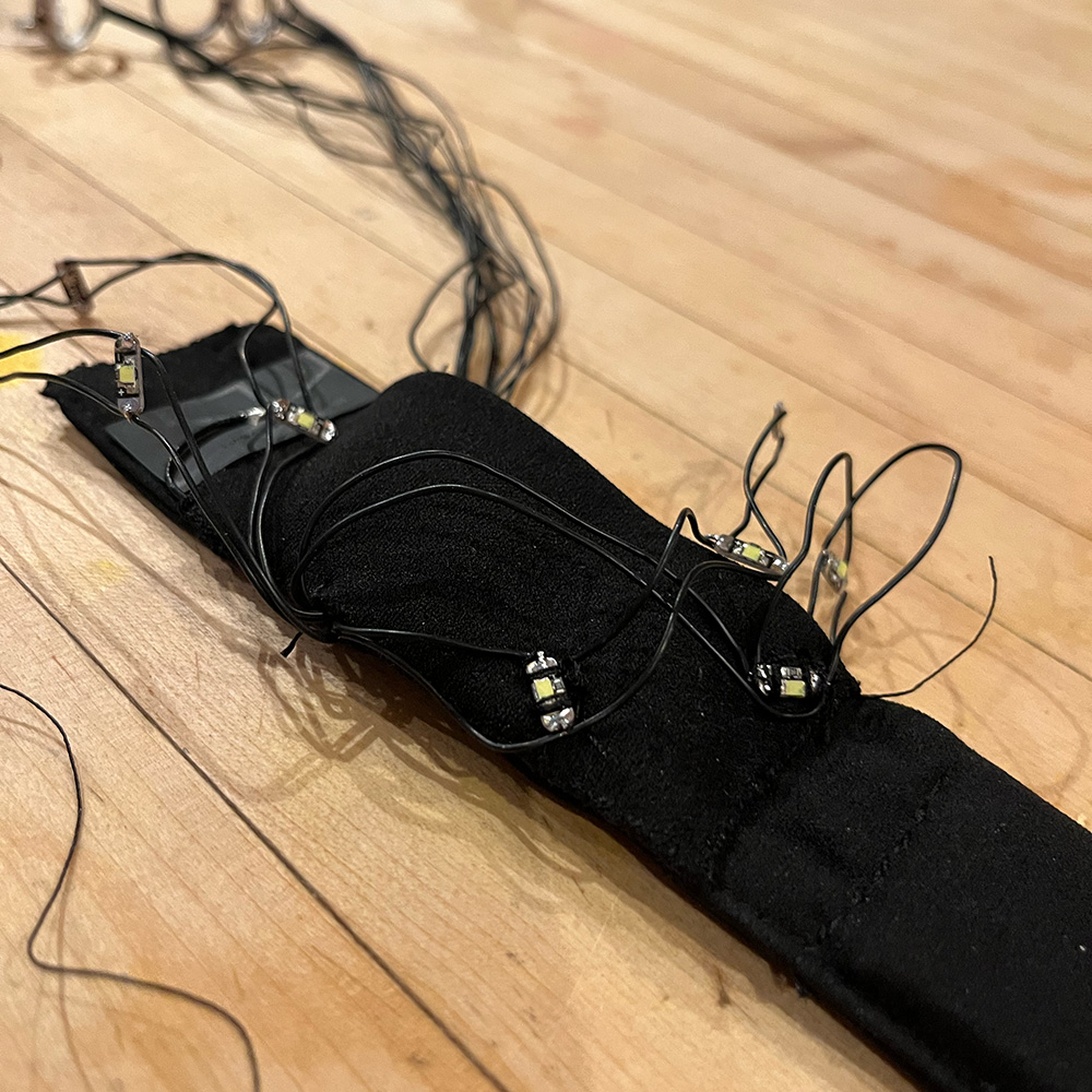
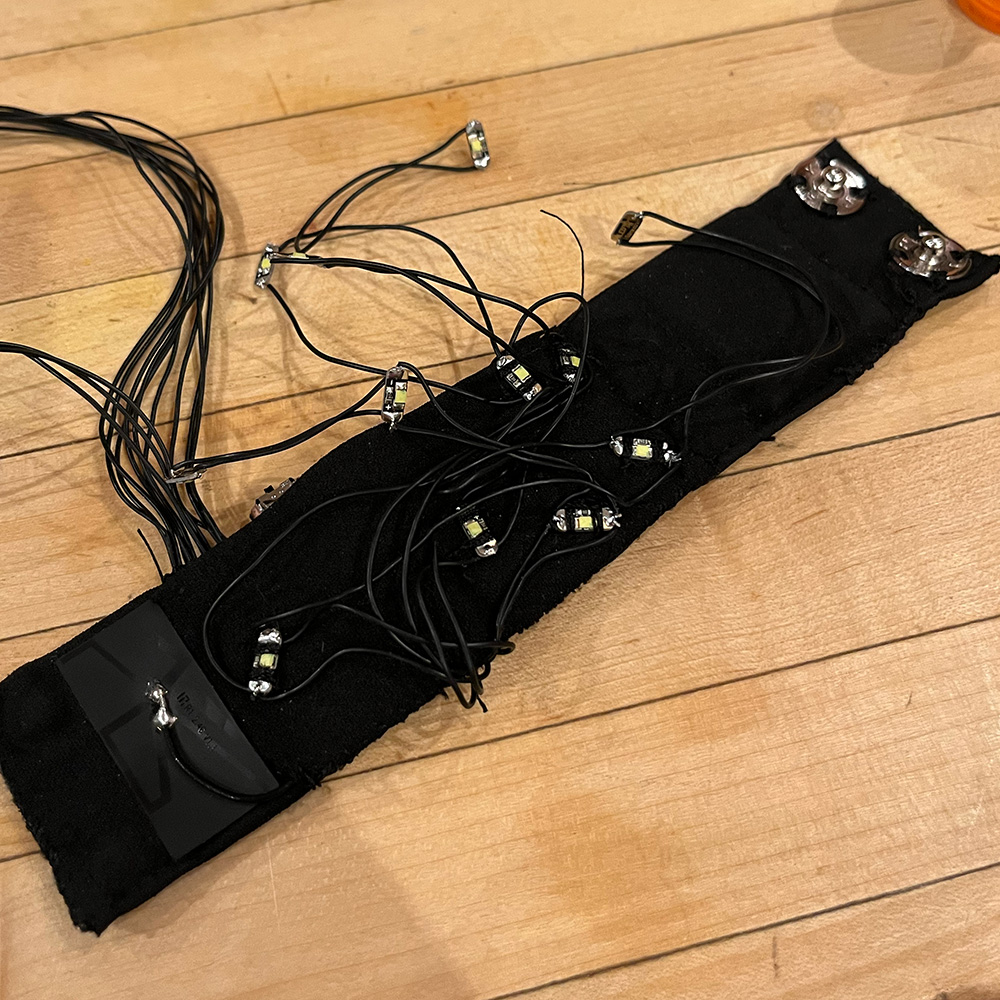
I stopped sewing to solder on the LEDs (adafruit "sequin" mini LED PCBs which I had wired together in sets of 3) and then left a gap in the bottom seam for those wires to come out of. I also left a gap for the antenna wire to feed through so I could stick that down as well (I didn't realize how important leaving the antenna uncovered was until fairly late in this process.)
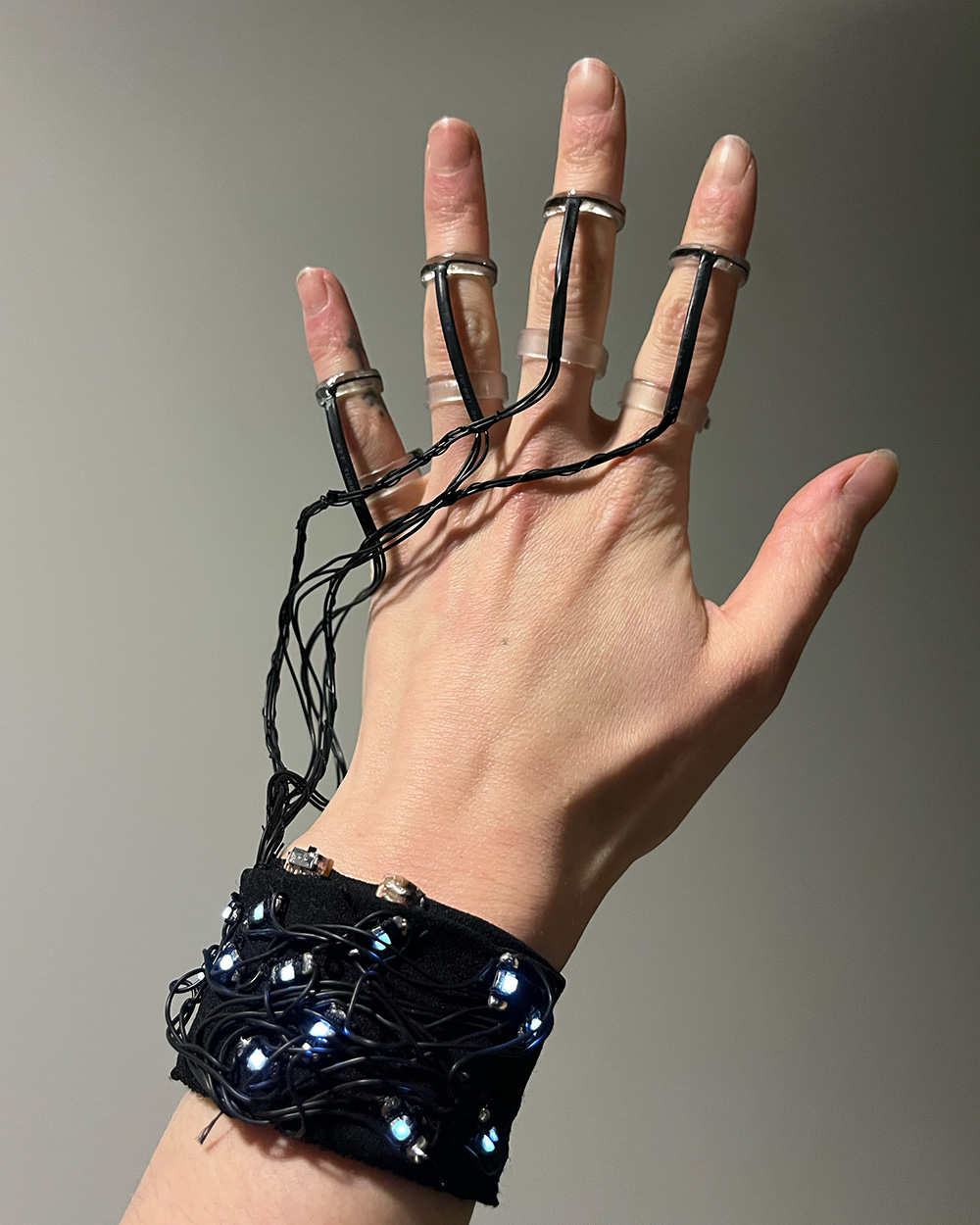
With the flap in place, I started sewing on the LEDs one at a time, hoping to create an interesting pattern while building up a tangled-looking nest of wires.
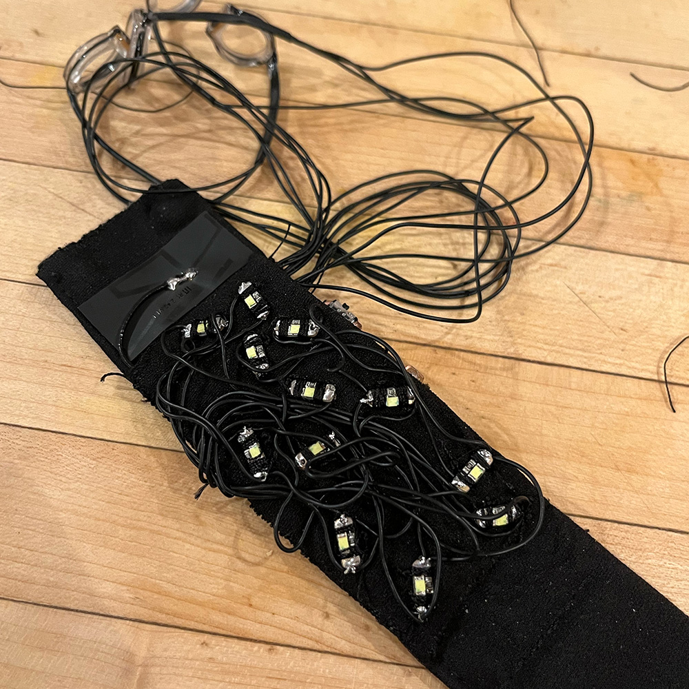
I like how it turned out overall- if doing this again I'd redo the LED layout to go further around the wrist, but I'm fairly happy with this.
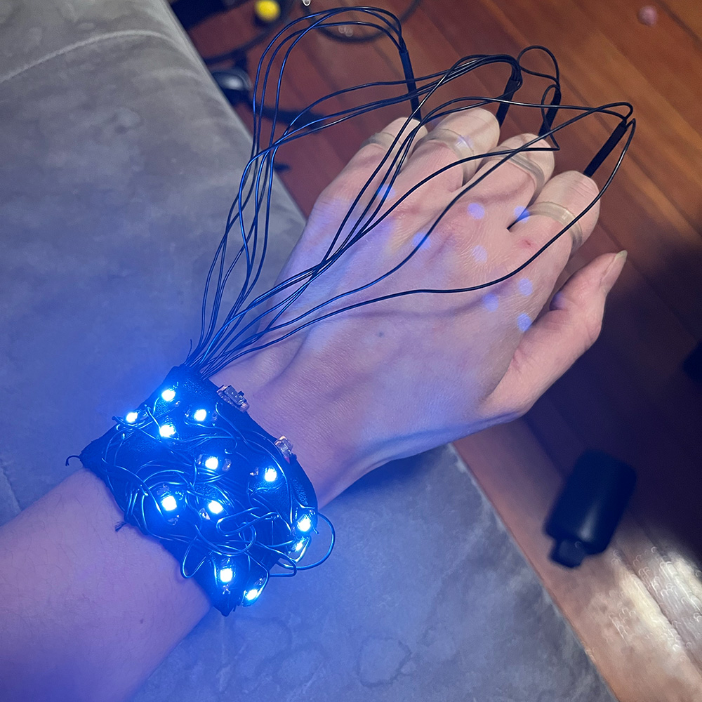
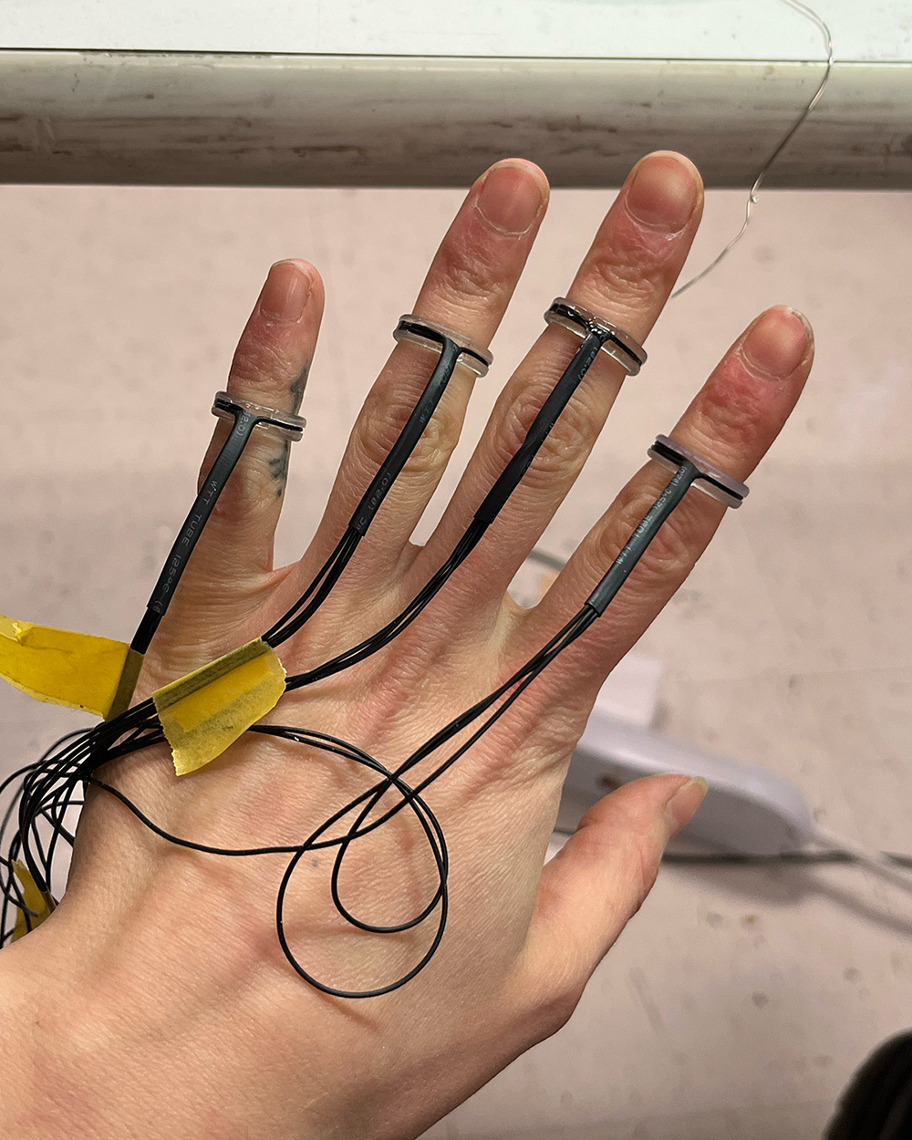
After this I wrapped some thread around the ring wires for the middle and index fingers just for the aesthertic, and the enclosure was finished!
For the microcontroller I used my code from week 12 so check out that page for the documentation. For the synthesizer/UI of sorts, check out week 13
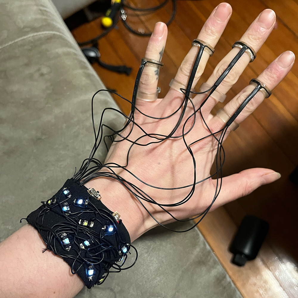
A note on the LEDs: when I first wrote the LED code I set the brightness threshold based roughly on what the sensor baseline was, but it's a little off, so the lights flicker like crazy when my fingers are straight. I could've changed this but I didn't because I think it fits the aesthetic perfectly. Yay for happy accidents!
I made a separate page for the bill of materials, which you can view here.
I wish I could say I was proud or thrilled about this right now-- anything other than exhausted, really, but that's not the case yet.
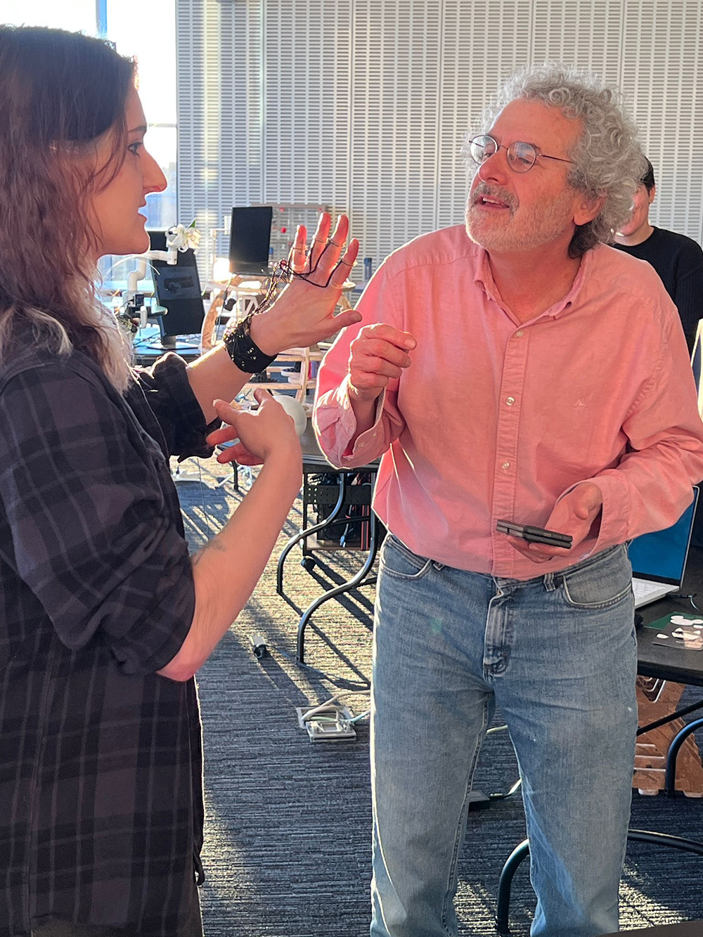
What do I think this project answers or does well? I think this application of hall effect sensors for finger bend tracking is unique and interesting. I would be really happy to see someone take inspiration in this and explore that further because it's an area of untapped potential. As Neil commented today, I think my project is very well integrated. And as many others noted, it looks cool and functions well. Designing wearables is really hard and carries a unique set of challenges about fit, flexibility, and comfort. I didn't solve all of them perfectly, but I made a system which works, and that's pretty impressive! I also stayed true to my aesthetic goals, even if they shifted along the way. I managed to pack a lot of stuff into a relatively small enclosure. Compared to the fancy tech out there nowaydays, it's not impressive. For what I was working with though? I think I did quite well.
As for what I would change or don't like as much, I wish I had been able to use more fabrication methods like I was initially hoping for. 3D printing was the last thing I expected to do here and I'm really glad I got to bond with the SLA printer because it is a fantastic machine, but there's much more out there. I'm reall proud of the skills I developed in this class
and I wish more of them were on display here. I will definitely be using those things in the future.
I would like to get a better satellite or find a better way to integrate the current one. That's something I wasn't prepared for and it's one of the biggest flaws in my interface.
But hey, bottom line is: it works, it's done, and I'm not too proud of it yet, but I'd like to think I will be soon.
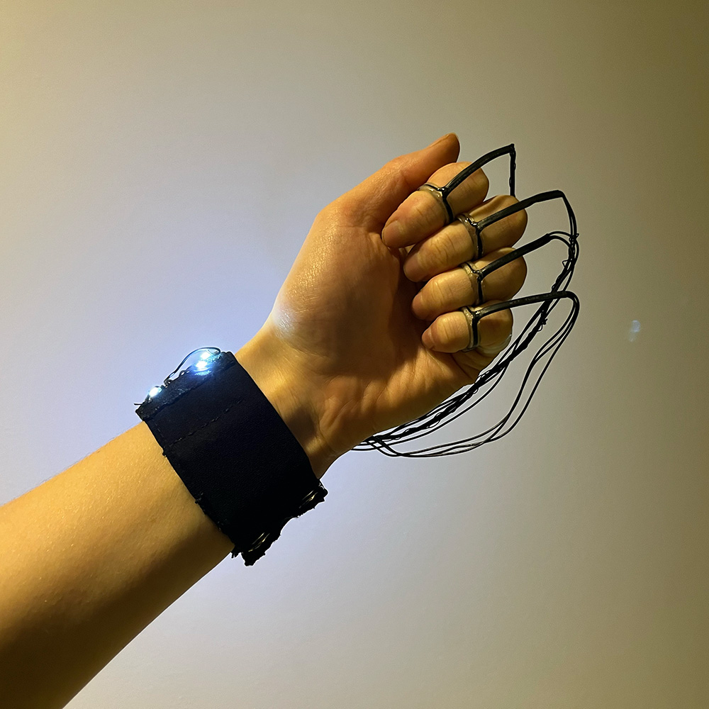
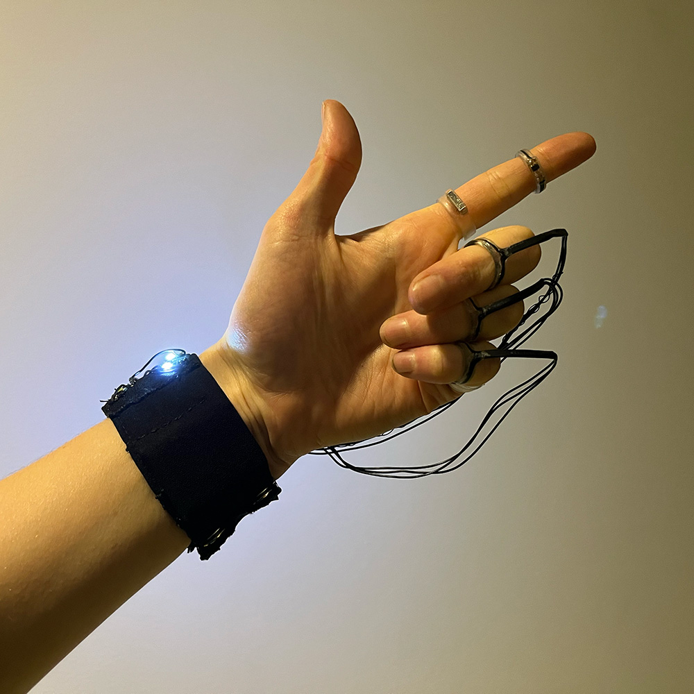
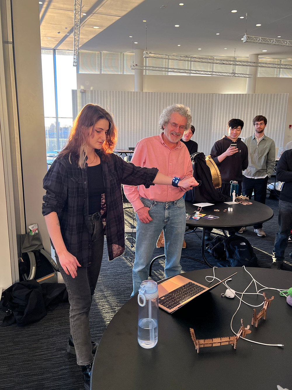
I hope to take some better videos of me playing it once I get some time to practice, but here are some photos I got of the final presentation and the finished project: