Your avatar

Aijia Yao

MIT EECS • HTMAA 2025

Week 5 – Electronics Design

October 2025

This week was mainly about PCB design and simulation.

What I Did

PCB Design Introduction

Fusion PCB

  • Make sure to import the library to have access to all components.
  • Make sure to set the design rules first before routing.
  • Make sure the edge of the board is here to leave enough space for connections.
  • vinyl
    A screen shot here with XIAO-RP2040 example
Note: Zero ohm resistor can be used to jump through wires.
vinyl
Above is the schematic design of the PCB with XIAO-RP2040 microcontroller, LED and series resistor as one of the simplest examples.

KiCAD Notes

Same setup as fusion PCB, need to import the library first.
  • Make sure to set the design rules first before routing.
  • Make sure to assign the footprint to each component in the schematic before going to PCB layout.
  • Make sure to set the board edge in PCB layout mode.
  • Use "B" to add tracks, "V" to add vias, "M" to move components, "R" to rotate components.
  • Use "F" to flip components to the other side of the board.
  • Use "X" to delete tracks or vias.
  • Use "Ctrl+Z" to undo, "Ctrl+Y" to redo.
  • Use "Ctrl+S" to save, "Ctrl+P" to print.
  • Use "Alt+3" to switch to 3D view.

What I want to design this week

  • Morse Code Flasher with XIAO-RP2040, LED and a button.
  • Use a push button to input the morse code pattern, i.e. dot and dash.
  • Use the XIAO-RP2040 microcontroller to read the button input and control the LED output.
  • Use an LED to flash the morse code pattern.
Component Specification
Microcontroller XIAO-ESP32-S3(simulation);XIAO-RP2040(real design)
LED NeoPixel Compatible LED (WS2812B, see datasheet)
Button Tactile switch (TS04-66-43-BK-260-SMT, see datasheet)
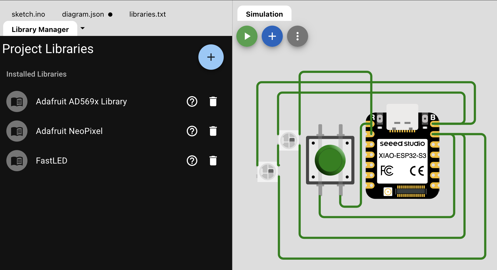
Then in Wokwi, include the components and wire them up as below, also make sure to include the necessary libraries. The link to the Wokwi project is here.
simulation page
Below is a demo video of the design with "HTMAA" as the morse code input, two led flash red when dash input detected and one led flsh blue when dot input detected:
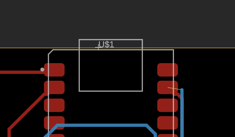
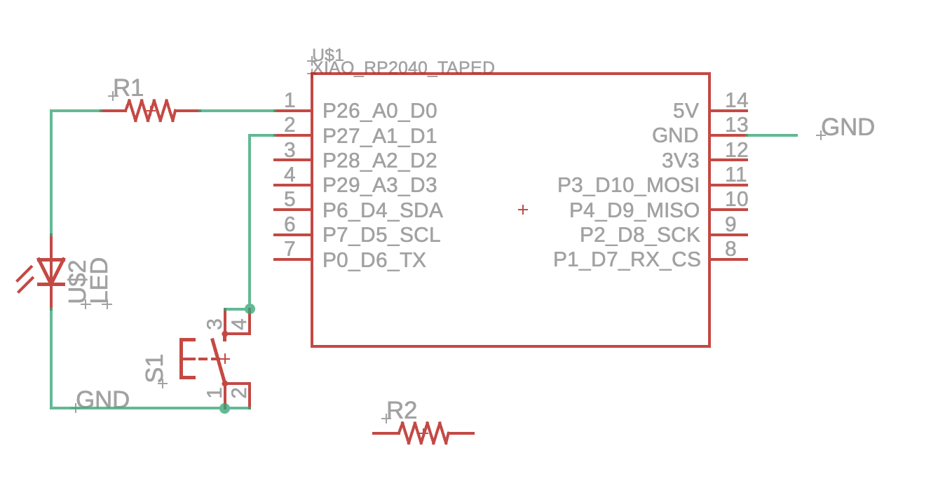
And finally, I used KiCad to design the PCB schematic and layout. Considering that the longest Morse code is "0" with 5 dashes, I decided to use 5 LEDs to represent the morse code. The schematic and layout are shown below:
simulation page

Other Notes

  • It's utterly weird that I was introduced to use Cadence Virtuoso for IC design first before the PCB design. The schematics of PCB automatically go to a layout so smoothly really amazed me.
  • The PCB layout design has been updated in week 6 and download link is here and the schematic file is here.